3. Computer Aided design
This week my aim was to explore different 2d and 3d software. I decided to try working on the following software. - GIMP and Inkscape for image processing
-
Freecad and Fusion360 for 2d and 3d modeling
-
Blender for rendering and simulation
Image Processing
GIMP
I inserted a photo in GIMP taken from a research about Mashrabiyas (link in references), I edited it by selecting and copying the part I needed and then pasted it in a new file. I then tried exploring some of the tools of the software just to get myself familiar with the interface.
- Adding text: “Text Tool”.
- Selecting an irregular shape within the image : “Free Select Tool”
- ctrl c = copy , ctrl v = paste
- To move the pasted image: “Move”
- For highlighting the inner shape I used the ” Paths Tool” and I edited the path stroke.
- I then made a copy of the shape, moved it, then rotated it using the “Rotate Tool”

Every change I made to the image was created in a new layer

To scale the image
From the top tool bar got to Image > Scale Image
Inkscape
I also tried to trace a raster image to turn it into vector by going to the tool bar and selecting > Path > Trace Bitmap.
I tried once with Brightness cutoff selected and the other trial was with Edge detection. I then changed the threshold to adjust the lines. Ticked remove background and unticked the other options
To change the color: Path > Break Apart, then selecting the part I want to color and give it a color from the pallet in the bottom bar.
Below is the results of my first attempt using Inkscape

2D DESIGN: FreeCad
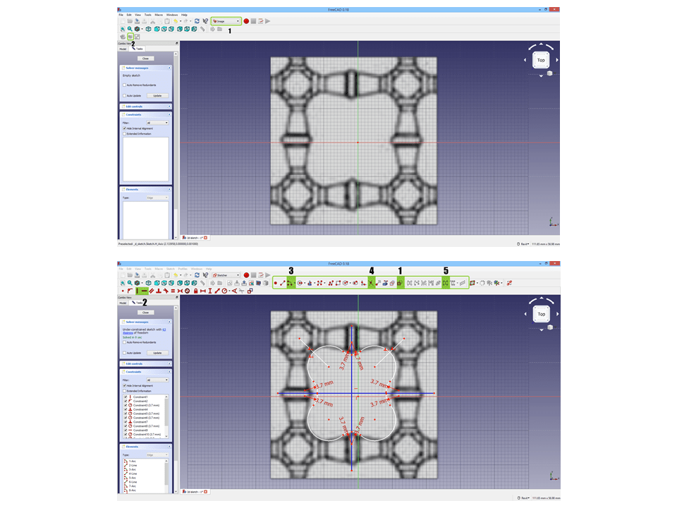
I decided to start with FreeCad for drawing in 2D. I had a shape in mind that I want to trace from a traditional pattern, so I imported the image to FreeCad and drew my lines over it following the next steps:
I. I switched my workbench to “Image” as shown in number 1, I then pressed on number 2 to choose my image and my preferred plane.
II. Using the “Sketcher” workbench, I created a new sketch and started drawing over the image.
-
I first set my lines to construction mode to draw axis lines so I can mirror my drawing on them since my drawing is symmetrical
-
I used the vertical and horizontal constraints to make sure my construction lines are perpendicular
-
I used the arc tool to draw the curves
-
“Trim” to get rid of the excess where lines intersect.
-
To mirror, I used “Create symmetrical geometry”
“For me, I found working with FreeCad as a first timer was simple. However, I got stuck at understanding the different workbenches and the difference between the Sketcher Wb and the Draft WB. I found out that sketcher is used to make a sketch for 3d modeling, whereas Draft is used mostly for 2d drawings. I was working on sketcher Wb before understanding this and tried to do some basic functions like move and offset but I couldn’t find them in the Sketcher. They were on the Draft Wb and when I tried using them it wasn’t allowing me for some reason which I found annoying and some other software like AutoCad would have done the 2d drawing faster. I’m sure I’ll need to look more to solve this issue and understand what I did wrong, but for now these are my thoughts of FreeCad!”

I also tried exporting my drawing to .dxf in order to import it to Fusion360 and start modeling with it. When exporting it didn’t allow me so I followed the steps as shown below and then tried exporting again

3D DESIGN: Fusion360
I started at Fusion360 by modeling a random shape and here is the result.

I noticed that there was something wrong with the planes, I then realized that in Fusion360, in order to sketch, I need to either be on a face or plane. In my case, I forgot to choose a plane.
Importing DXF to Fusion360
I then decided to import my 2d layout of the shape that I drew in Freecad. In the video below you can see the steps I took to do so.
After importing, I fixed some lines until I was happy with the shape.

I liked how most of the functions can be done from the keyboard shortcuts. For example, when sketching pressing S opens the model tool box then for instance I can type offset and here we go! “
When I inserted my .dxf file, the lines came in several parts and were not connected. So I was trying to find a way to make them all connect to become one closed shape so I can model it. I used an Add-in called “ConnectTheDots”. I needed to install it by downloading the script and copying it in the right folder.
For more details about “ConnectTheDots” see links below:
After installing I faced a problem where it was giving me a weird shape. I tried removing the curves that I trimmed from a circle and tried again then it worked. a window will pop and should show 0 Errors.

I then started modeling and everything was fine

Here is the results of my first attempt in modeling my prototype in Fusion360 (Ignore the obvious mistakes and the messy modeling)

“I liked working with Fusion360, I will sure go back and work on it for my future projects. It’s interface is easy and straight forward. It has many great features. I mostly liked the Live Review feature. It makes sharing and viewing files with other people much easier and more interesting!”
Last step I made in Fusion360 was trying the rendering tools. The software allows you to explore variety of embedded materials within it just by choosing to show downloadable materials from the “Apperance” tool box. From there, you can choose materials and edit them. I then made other changes to the background colour from the environment settings and then set it to render. The image below is a result of a fast canvas render.
