14. Networking and communications
Important Note:
I have used the networking protocol in my final project using RS485 to Serial Converter To Cross Talk between the different modules of my final project.
The Module I Used For Serial To RS485 is XY-017, For more information about
- RS485 please Click Here
- XY-017 Please Click Here
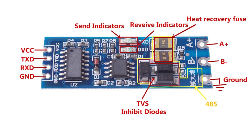
the reason for me to choose this protocol is the limitation of I2C protocol via long wires, where as the RS485 is capable of sending information for long distances via wires up to 2 kilometers not to mention that the capability to integrate it with industrial PLC (programable Logic Controllers) because Rs485 is and industrial communication protocol and also most PLC have ports for it too. so expandability with minor changes was an extra benefit.
so basically I used serial communication via serial port to transmits and read data from and to other modules. I didn’t go with the flow of master and slave, I used simple methodology that gets the thing work. Its more like I build my own protocol
- To Read Weight From Smart Scale I Send “RW” to the buss
- To Read Height From Height Sensing Module I send “RH” to the buss
When this two charters are sent to the buss, all circuits are able to read them but only the microcontroller unit who is mint to respond to this two characters that match will reply back.
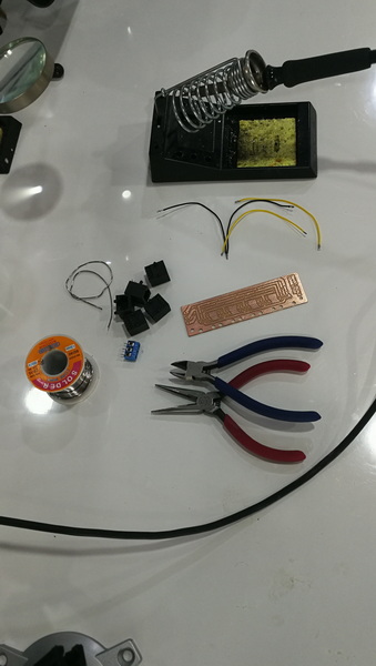
Parts I Used
in this part of the project I used 1. Ethernet Cables 2. RJ45 Terminals 3. RJ45 PCB through hole sockets 4. Double Sided PCB - Because The Single Sided Where Over 5. XY-017 Module 6. Buck Converter Step Down 7. HX711 Digital Weight Scale Loadcell Amplifier 8. SMPS 12v Power Supply
and I planned my own pinout connection and created my own connector boards too
My Choice Of Preferences
in order to achieve the communications with 3 separate units that are far away from each other I had to use long wires, I decided to use Ethernet cables for wires
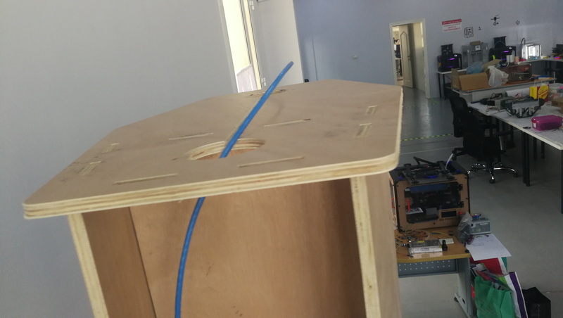
The Height Sensor Unit Placement
This picture is for the cable for the height sensor units
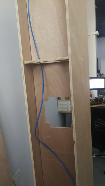
This is For Weigh Scale Unit Placement
This picture is for the cable for the height sensor units
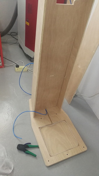
This Hole And Wire Is For The Central Unit Placement
This picture is for the cable for the height sensor units
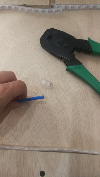
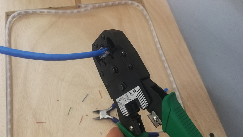
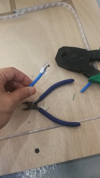
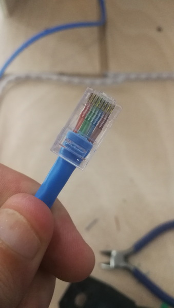
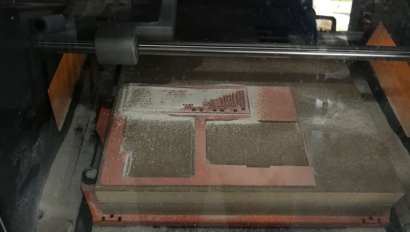
The Crimping Process In Pictures
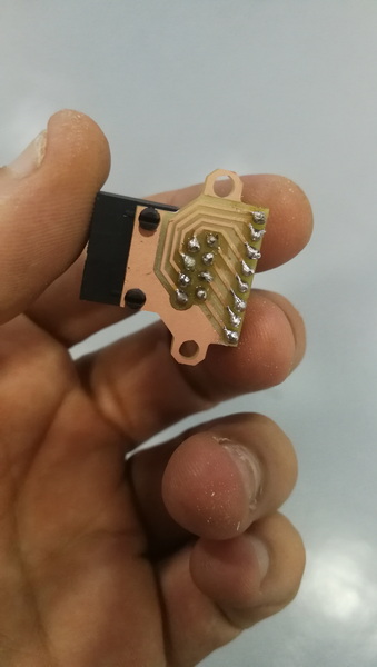
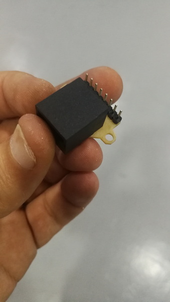
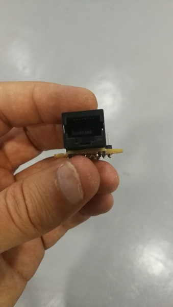
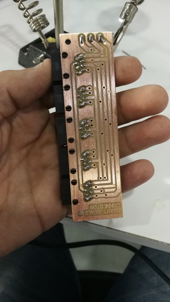
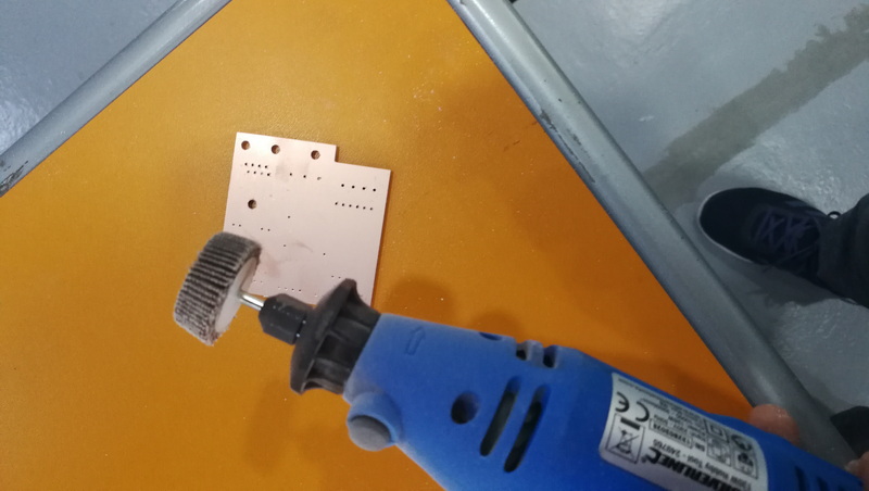
PCB Milled Small Connector Boards For Units
these small RJ45 Boards are used beside the units I made it this way because in case of misconnection or a mistake in routing on the PCB may be time consuming and costly, so I preferred to create them spartanly so just incase I can change the connection via jumpers.
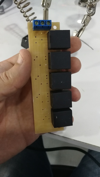
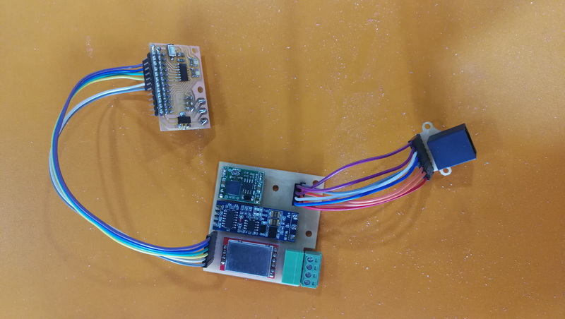
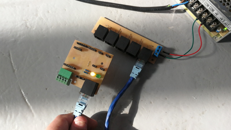
Power And Modules Connector Board
all the circuit needs power to run, and needs communication wires to give them the capability to communicate easily. so I thought of making a main board that have all the necessary connection to distribute power and connect the communication wires together.
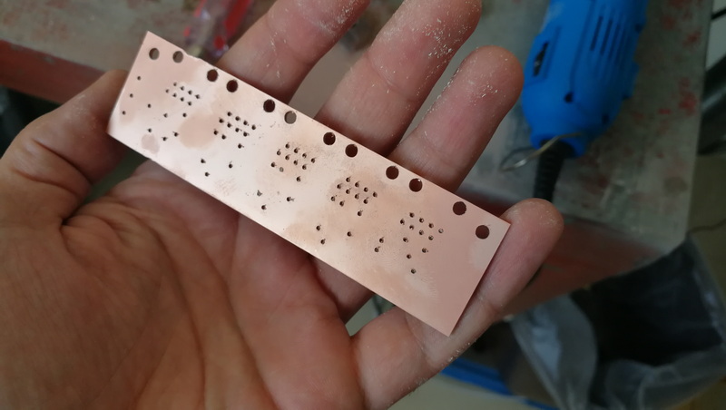
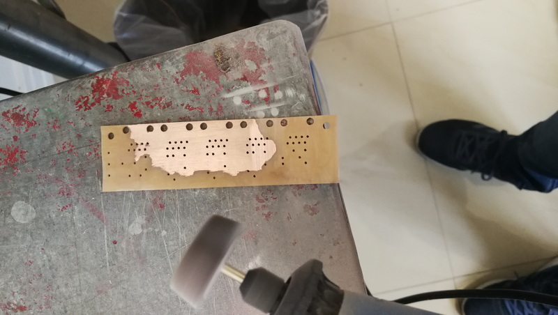
since what we have is a double sided board I have to remove the copper on the other side of the board to avoid short circuits.
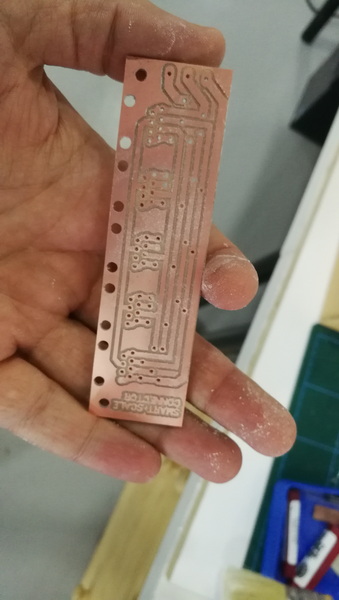
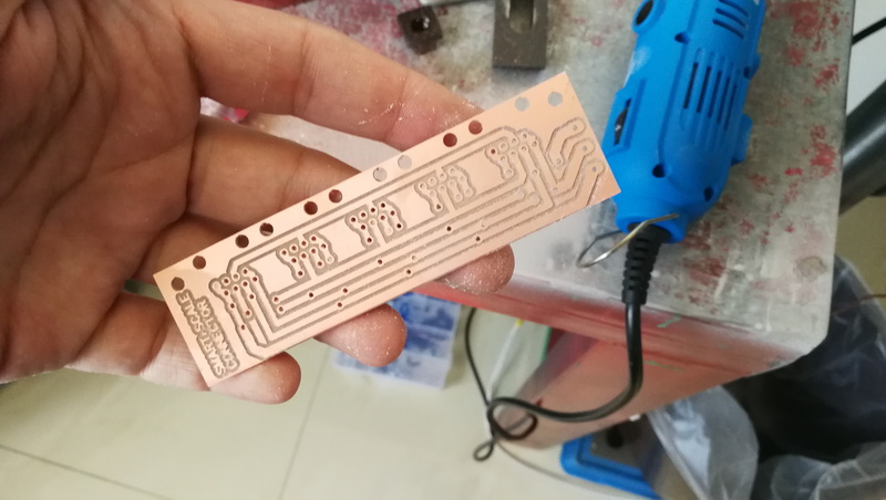
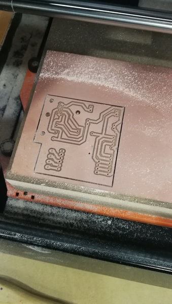
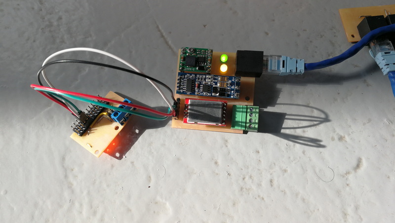
This is weight Scale Module
this is the weight measurement unit communications board
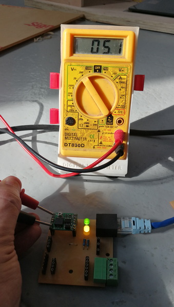
Adjusting Power Supply And Testing Connection
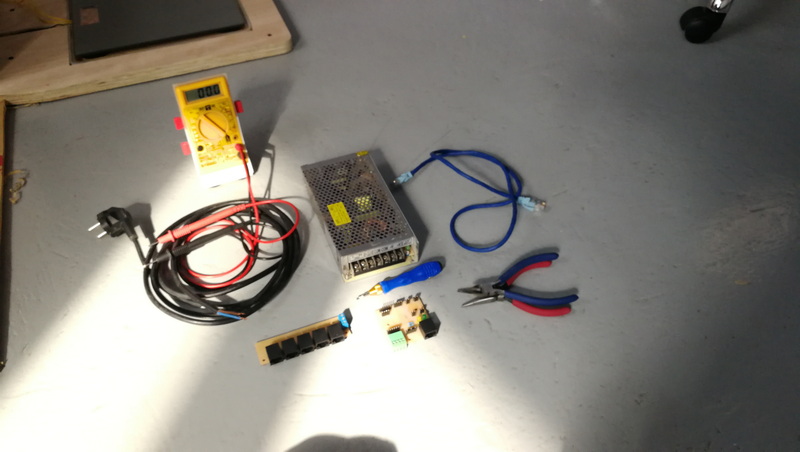
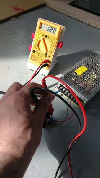
Testing Power Delivery
Testing Weight Scale Buck Converter
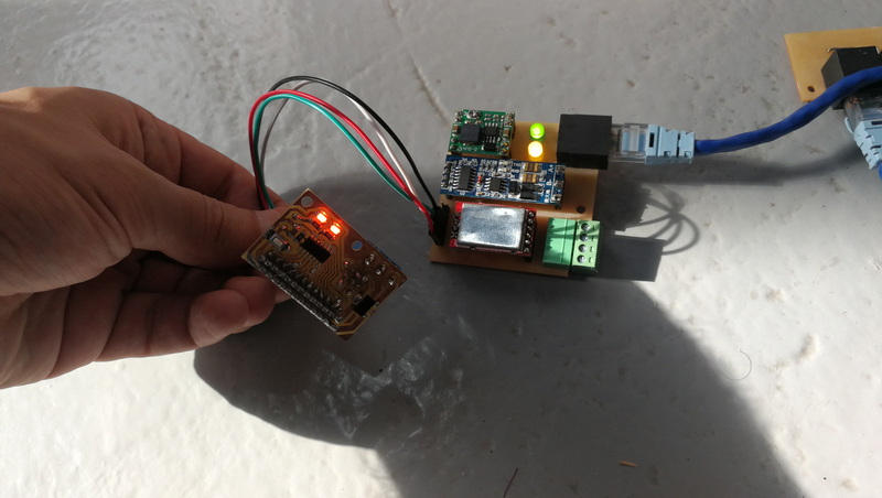
Putting Weight Scale All The Components Together
Tadaaaaa Its Working
Problems I Faced
this project is multiple projects onto one, which means lost of connection and lots of components and much of every thing. therefore I have gone into communication problems and burned one of the module that I have due to crossing line with power. what I learned from this that its easy to build a protocol just like humans behavior talk, for example a teacher is a master when he calls out for a student all students listen but only the one pointed to responds back with the answer. this is simple basic networking methodology.
Firmware Code
I used Arduino IDE to write the following firmware code, and
Sender Example Code
void setup() {
  Serial.begin(9600);
  pinMode(2, INPUT_PULLUP);
  pinMode(3, INPUT_PULLUP);
}

void loop() {
  // Sending Height Request Code
  if(digitalRead(2) == LOW) {
    Serial.println("RH");
    delay(100);
    // Receiving Code
    if(Serial.available()) {
      float avg;
      for(int i=0; i<5; i++) {
        String x = Serial.readStringUntil('\n');
        x.trim();
        avg += x.toFloat();
      }
      avg /= 5;   // Calculating The Average Height
    }
  }

  // Sending Weight Request Code
  if(digitalRead(3) == LOW) {
    Serial.println("RW");
    delay(100);
    // Receiving Code
    if(Serial.available()) {
      float avg;
      for(int i=0; i<5; i++) {
        String x = Serial.readStringUntil('\n');
        x.trim();
        avg += x.toFloat();
      }
      avg /= 5;   // Calculating The Average Height
    }
  }
}
Receiver Example Code
void setup() {
  Serial.begin(9600);
}

void loop() {
  if(Serial.available()) {
    String x = Serial.readStringUntil('\n');
    x.trim();

    if(x == "RW") {
      // If The Two Characters That You Received Match RW then do some response Here
    }
  }
}
Video Demo
Note : In the Video above I first tested everything with Arduino Uno for the east of programming via USB cable rather than using my boards because I will need a programmer and a USB to serial chip to debug it, there for I first tried it with Arduino and made sure it worked then I swaped them with my attiney84 boards
Display Unit Code
- To download the code plz click here
Weight Scale Unit Code
- To download the code plz click here
Height Scale Unit Code
- To download the code plz click here
Boards Design
- ATTINEY84 click here
- RJ45 Board click here
- HX711 Board click here
- Connector Board click here
Group Assignment
- Please Click Here