7. Electronics design
This week I planned to make an electrical reflow oven to help us in class to solder the components faster and a more efficient ant time effective way. so since I am planning to make the oven, I need some kind of controller board, to control the oven heat and time periods of the reflow
- Preheating
- Thermal Soak
- Reflow
- Cooling
- Washing
so I have went to market and purchased an electrical oven to dismantle
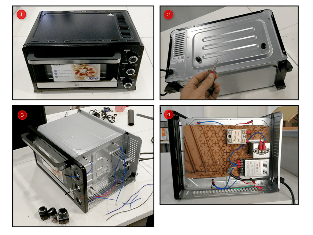
- The Oven
- Removing The Top Cover
- Removing All Parts
- Installing a wooden plate and Add Some Components
Design Main Board
I used EASY EDA for designing the electronics circuit board because it has all the components foot prints which is collectively contributed by the community, most likely you can find all the components and their foot prints and you can create groups to collaborate in the design and it has a built in versioning functionality
Import (Eagle Fab Academy Library)
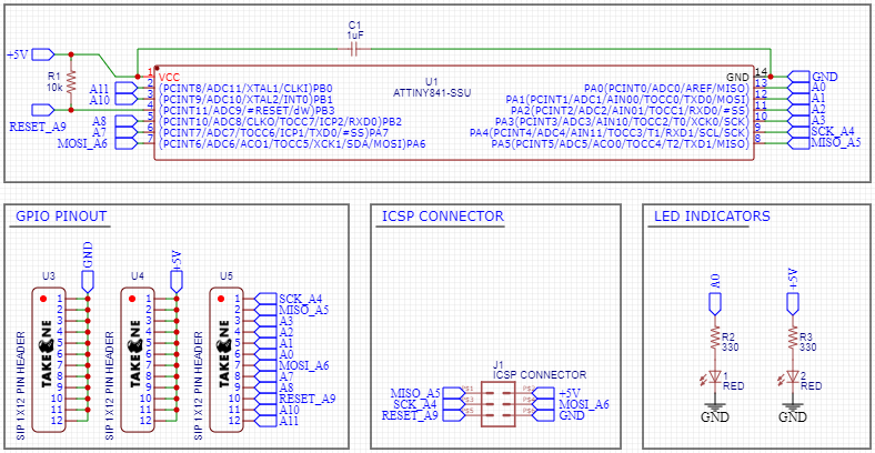
Design The Schematic
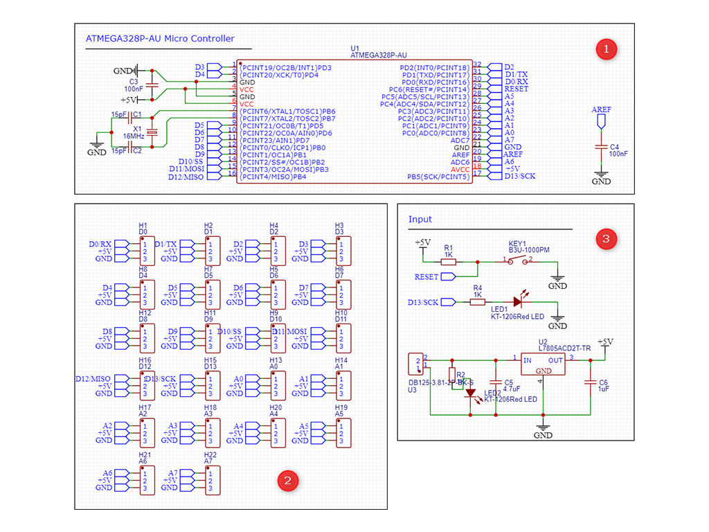
- The microcontroller power and clocking crystal
- Pin headers for GPIO with power and ground
- The Inputs & Outputs On The Board Button / LED / Voltage Regulator
Design The PCB
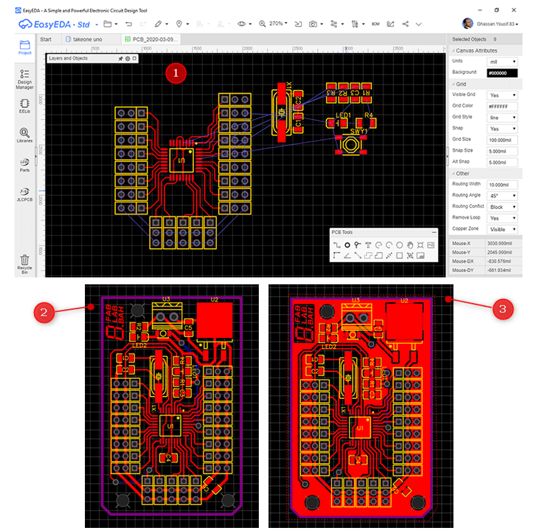
- Beginning of the design process
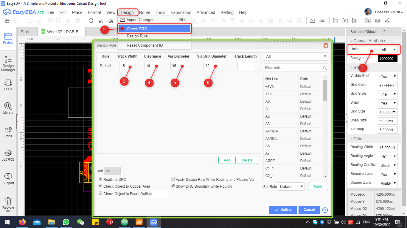
- Adjusting Design Rules To Avoid Errors
- After placing the components and routing everything successfully
- Adding a copper layer and FabLab Bahrain logo
Milling The PCB
I started milling the PCB using 1/64 inch milling bit, and accidentally broke it while milling.
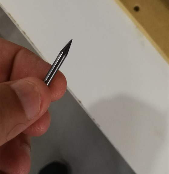
but on the second attempt it went great below is the milling results
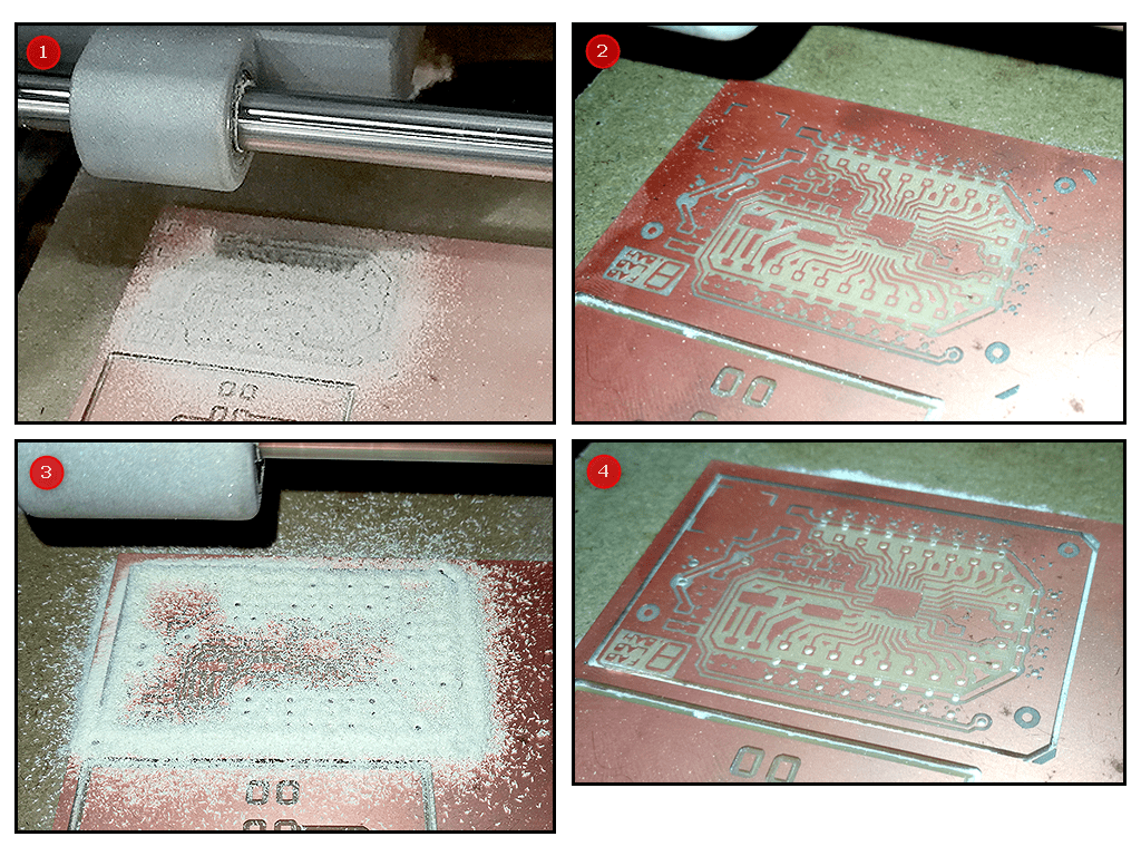
- Milled The Top Layer
- Cleared The Dust To Make Sure All Tracks Are Fine
- Started The Cutting Using 1/32 Inch Cutting Bit
- Removed The Dust To See The Final Result
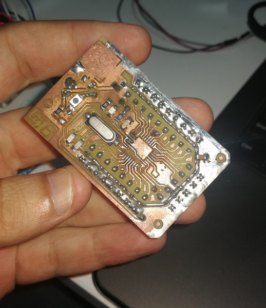
Finally Removed The Board With Clean Finishing
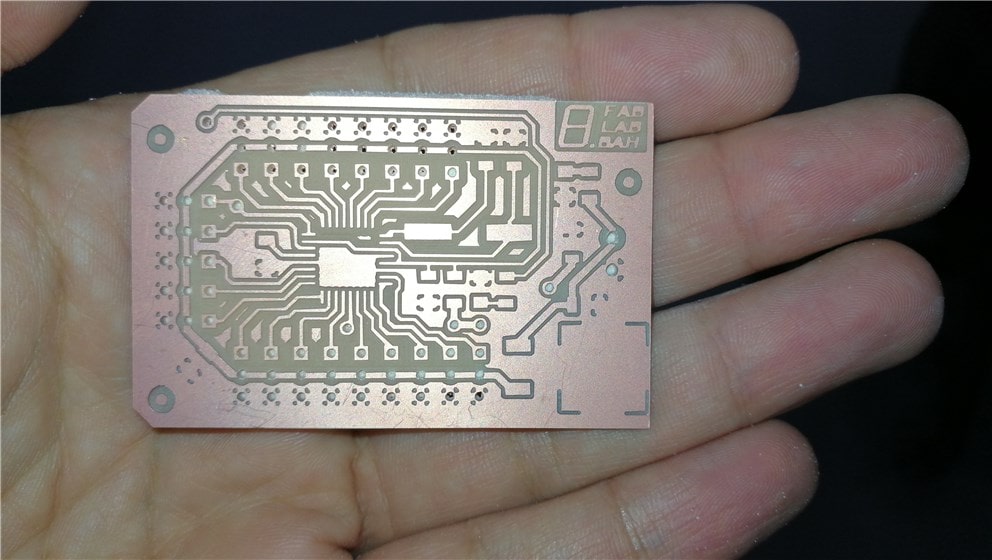
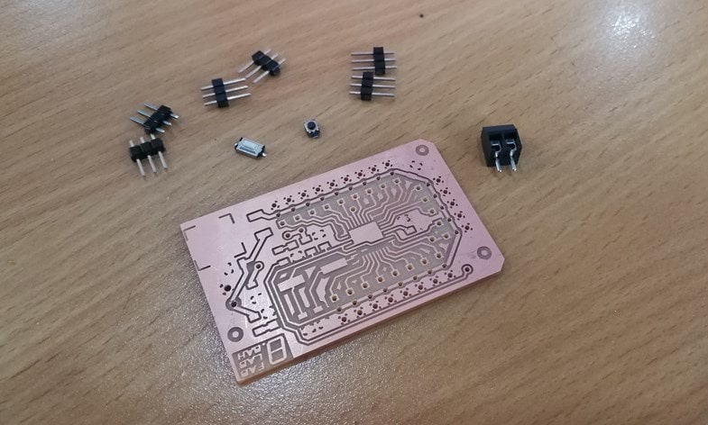
now I am in the process of collecting the required components and getting ready to solder
things I found out that went wrong with the milling process, when I was drilling the through holes for the bit have eaten the pads surrounding the hole. I should have made them a bit bigger, and the mounting holes, have been eaten only the surrounding, not the hole itself.
In addition while testing I burned the circuit due to wrong connection of wires because I didn’t make them out so I swapped the wires and got it fried :(
Rebuilding The Circuit With ATTINEY84
I decided to build the circuit with a simpler micro controller that is solder able to me and easy to find faults, the foot print is a bit larger and also the pin spacing is doable for me. below is the pinout diagram of the ATTINEY84 micro controller
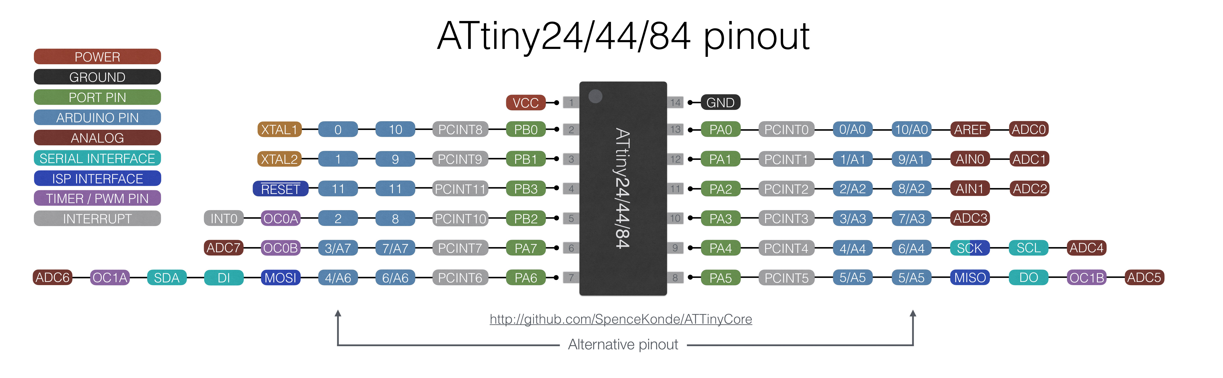
In order To dive in the details of the chip -> Download The Datasheet Click Here
Drawing The Schematic
Drawing The PCB Layout

In order to download the SVG Files please Click Here
Easy EDA Design Files -> Click Here
Milling & Soldering
I have gone through the very same steps as the previous one but I took care that it would be cleaner and without short circuits or errors.
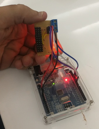
Connecting ICSP & Powering Up The Circuit
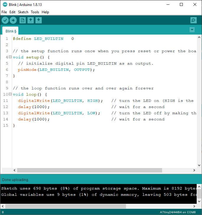
Uploading Blink Program (Firmware Using Arduino As ICSP)
in the first step I have to prepare a blink program, and change the LED_BUILTIN definition since I custom made our circuit board, so I connected the LED to pin 0.
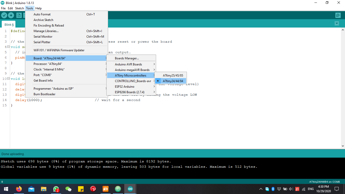
now I go to tools menu to select the Arduino micro controller that I am using Attiney84
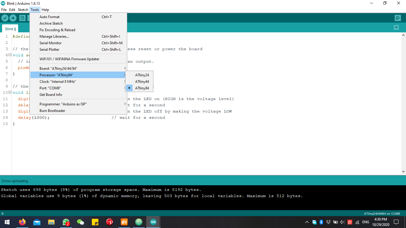
then I select the Arduino family processor variation Attiney84 since the family have two other ranges.
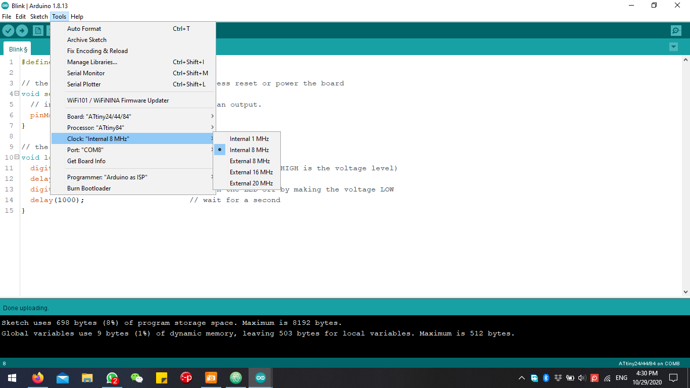
in my circuit design I didn’t use a crystal oscillator since I already have an internal one and to make the circuit connection simpler I selected the 8 MHz, so I have to specify where did I get my clocking from.
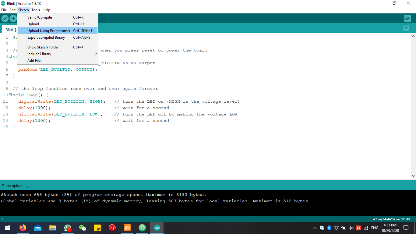
then in order for me to upload the program using Arduino UNO as ICSP programmer I have to go to sketch menu and select upload using programmer.
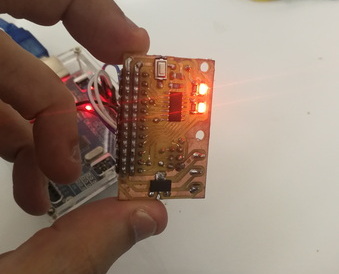
Hero Shot That My Circuit Is Working
Finally explaining what are all the components and where should our board be placed
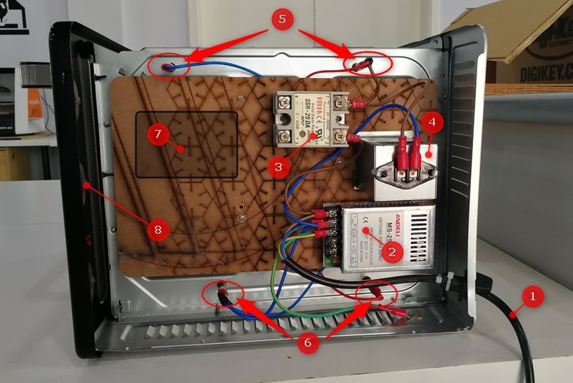
- Power Cord
- Mini 240VAC/12VDC Switch Mode Power Supply
- Solid State Relay For Controlling The Heating Elements
- Lamp 240VAC
- Top Heating Elements Bar
- Bottom Heating Elements Bar
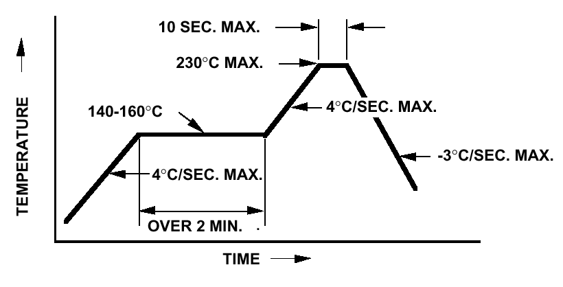
Manufacturers Recommended Reflow Profile For Standard SM LEDs
Group Assignment
Please Click Here