17. Machine design
The group assignment of this week is to actuate and automate our machine and to document the group project and your individual contribution
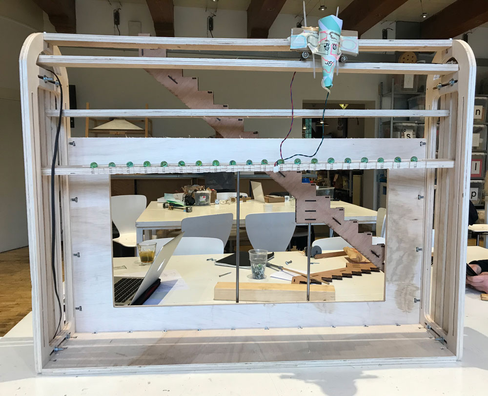
Our machine
 Our Marble Calender Machine
What does it do?
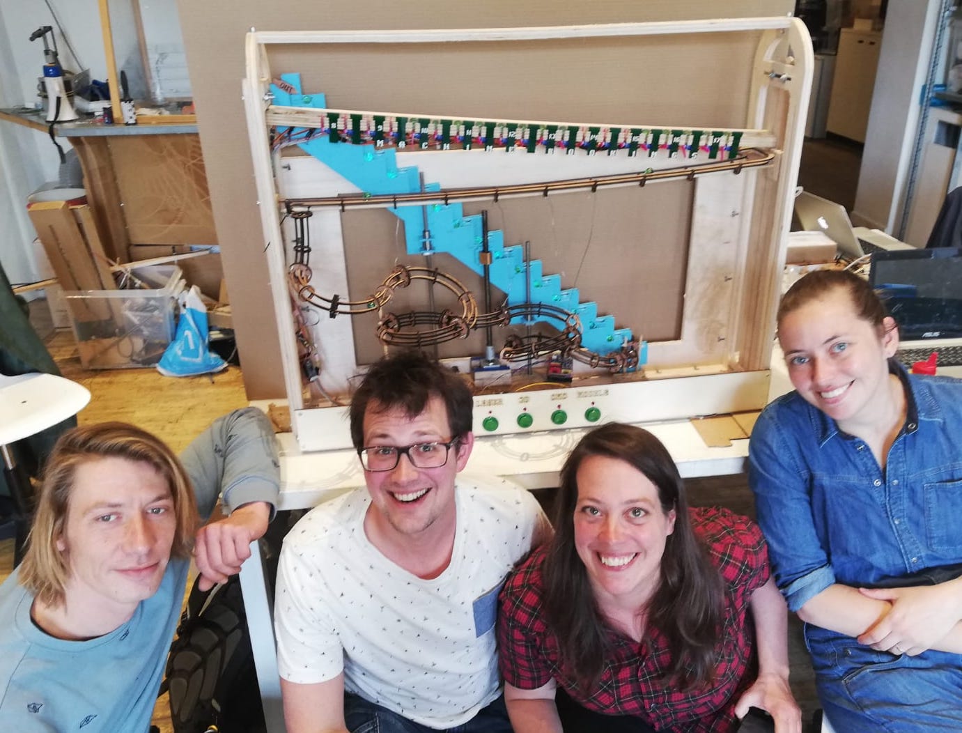
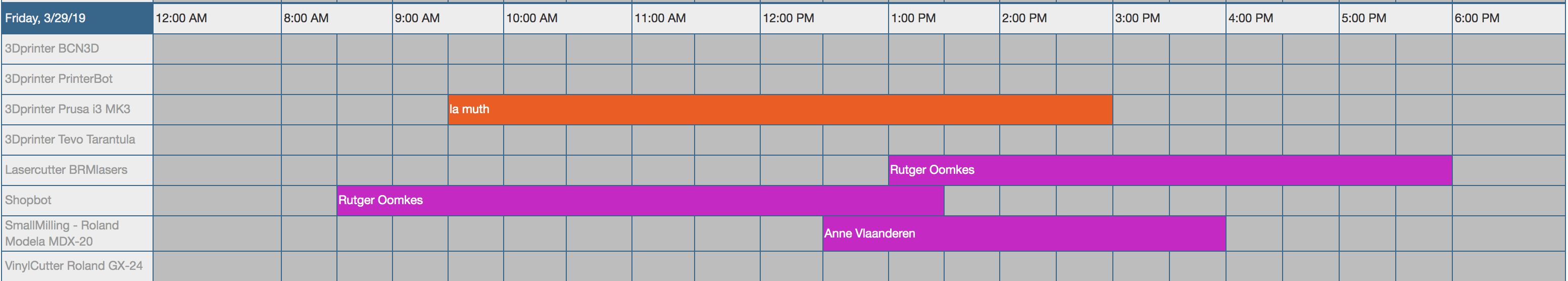
The machine is a physical representation of the online booking system of the machines at the Waag Fab Lab. It shows the reserved slots for the selected machine: CNC, Modela, Laser or 3D-printer. The machine will start moving marbles around, when it’s finished the marbles show which slots are open for you to use the machine and which slots are reserved. This way you’re always sure if and when you can use the selected machine. And you don’t have to go to the online to see when the machine is booked today.
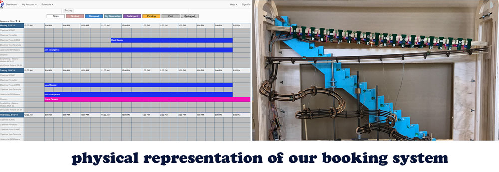 The Marble Calender Machine: a physical representation of the Waag fab lab booking system
How does it work?
- Press the button for the machine you want to use and see if it’s reserved
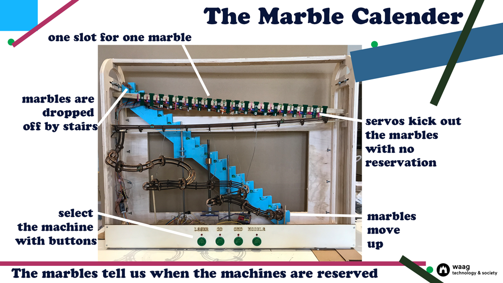
- After you selected the machine the stairs start moving and marbles start rolling, up the stairs and into the calendar slots.
- Each slot first fills with one marble, this represents half a hour, from 8.00 to 18.00.
- The machine is connected to the booking system of the Waag Fab lab. Based on these bookings it will kick out the marbles from the slots that aren’t reserved.
- These marbles go down with the marble runs back to start of the stairs.
- The marbles that stay in their slot show the reserved spots of the machine for today.
- When you want to see the reservation of another machine you press the button of the CNC for example.
- The machine starts over again with filling the slots and losing its marbles.
 The Marble Calender Machine: how does it work
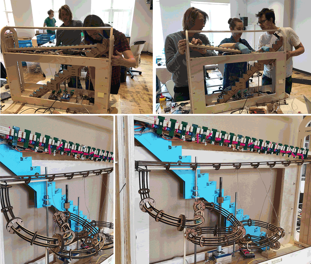
Who made it?
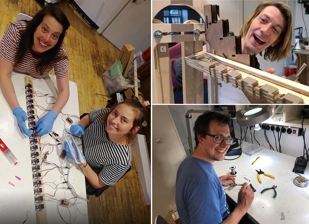
We had a lot fun and of course some stress for the deadlines working together as team on our marble calender machine. Details on each of our processes can found on our individual Fabacademy pages.
 Waag Fab lab team: Anne, Micky, Rutger and Joey
A marblelous team
- Joey likes to make stuff. he is a researcher at the Amsterdam University of Applied Sciences, where he works with Internet of Things technology and research assistive technology IoT for people with a visual impairment.
- Anne was the lab manager of Makerversity in Amsterdamis, now she is a freelance designer and maker on a mission to create, learn and and share.
- Rutger has a background in Anthropology but since a few years he dedicate myself to designing and making. This is where he found his true passion. He works with silicone to make jewelry and his trade mark is that all of my pieces don’t use closings.
- Micky is lecturer at the department of Communication and Multimedia Design at the Amsterdam University of Applied Sciences. She teaches courses about Design Ethics and Design Argumentation. She loves to combining theory and philosophy with applied design work.
The mechanical design
What we did step-by-step
For the mechanical design week the goal is to build the mechanical parts of our machine. First we brainstormed a couple of times for ideas for possible machines:
 The movable grinder
- dogbone eliminating machine - the movable grinder
- solar panel robot that always wants stand in the shade
- table robot vacuum cleaner
- light painting machine
- carrot cutting machine
- something with marbles
Step 1: Choosing an idea and brainstorming the design
After some brainstorm sessions we agreed with Joey’s idea which is an Marble Calender Machine.
 Our Marble machine is a physical representation of the Waag fablab booking system
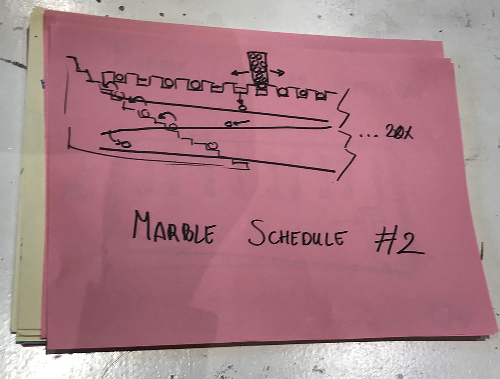
In our Fablab we work with an onlinebooking system to reserve a machine, see image above. You can reserve a machine and you can see if someone else reserved it. However you need to go online to see if a machine is reserved. We want to solve this problem with our Marble Calender Machine. We’re going to design and build a visual and physical representation with marbles of our booking system in our Fablab.
 First ideas for our Marble machine
After we decided on this idea we brainstormed and discussed a lot of possible mechanics for our marble machine. And we defined our first basic requirements.
- The machines can be reserved from 8.00 till 18.00 and you can book the machine for each half an hour. This means we need 20 marbles to represent the calender.
- We first decided that we would work out the calender for four machines: the laser, one 3D-printer, the Shopbot, and the Modela.
- Joey researched for an API to use, which available for our booking system.
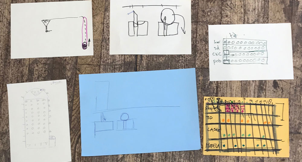 First design ideas for our Marble machine
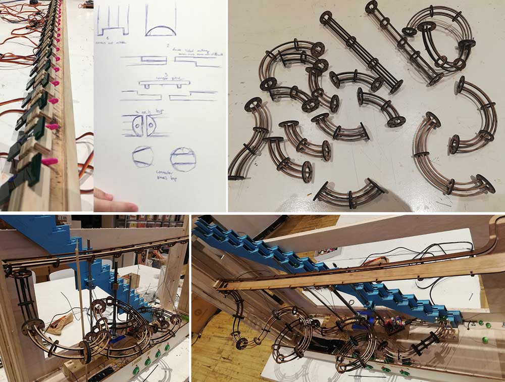
Step 2: Prototyping our initial idea
We build a quick cardboard prototype to see if our initial idea for the basic mechanics of dropping a marble in a time slot would work.
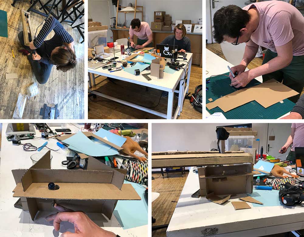 Prototyping with cardboard
We each worked on different parts, Anne and Micky worked on the marble dispenser which goes on top of the machine, and Rutger and Joey worked on the marble placement and the mechanics of dropping the marble in the right slot.
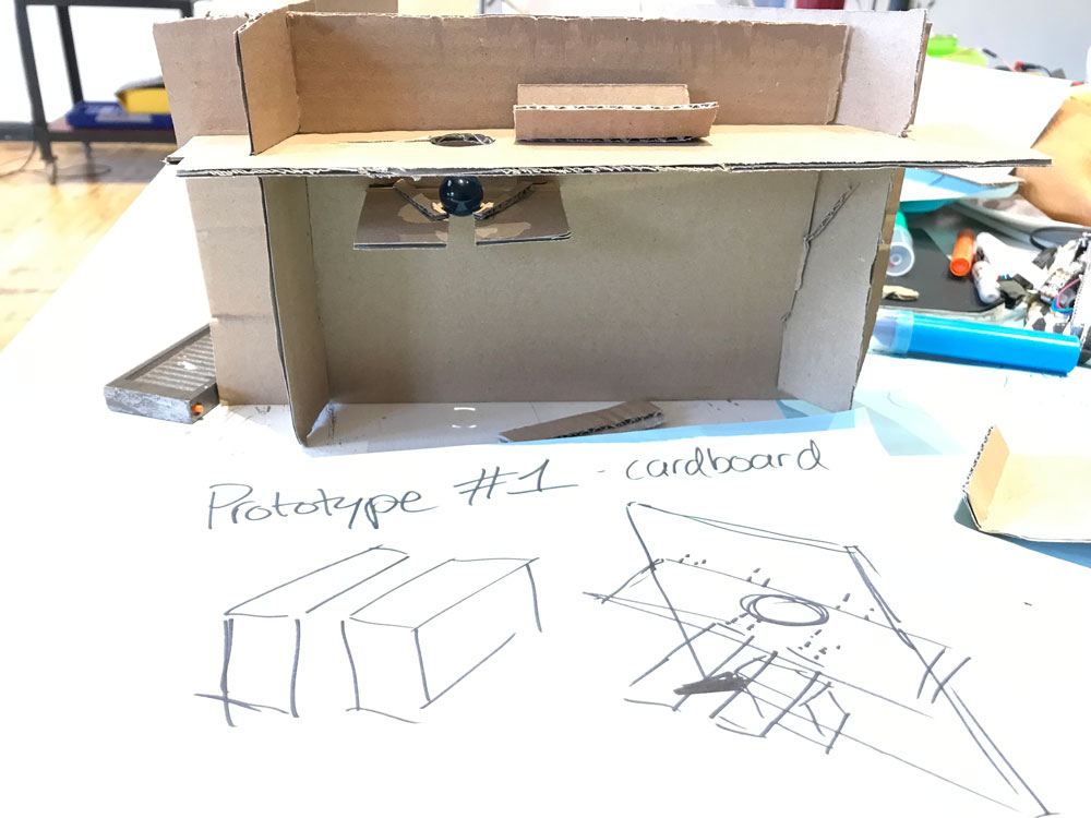 Prototype 1 made with cardboard to test the mechanics
Joey added a servo to see how this would work. This process and the cardboard prototypes was a nice quick way to visualize our initial idea and to get a better understanding for the mechanics of our Marble Calender Machine.
Testing our initial idea about the mechanics
Step 4: Making a planning and dividing tasks
After we prototyped our initial idea we got a better confidence and idea about what we would make. We also decided to change some parts. We all sketched the machine as we thought we would look like, based on these sketches we discussed what would be the best solution. In the end we decided to combine a design from Anne with one from Joey. We will use a dispenser for the marbles and we will ‘kick-out’ the marbles from the slots that aren’t reserved.
 New version of marble machine based on our prototyping tests
This gave us some new requirements:
- We will start with making the agenda for one machine (in stead of 4).
- Ideally we want to add interactivity, so you can select the machine you want to see and the marble machine will represent the agenda for the machine selected. This way we only need the one calender line.
- We decided that we will trow out the marbles of the slots that aren’t reserved with a servo, this means we also need 20 servos.
- We need need something to bring the marble back on top.
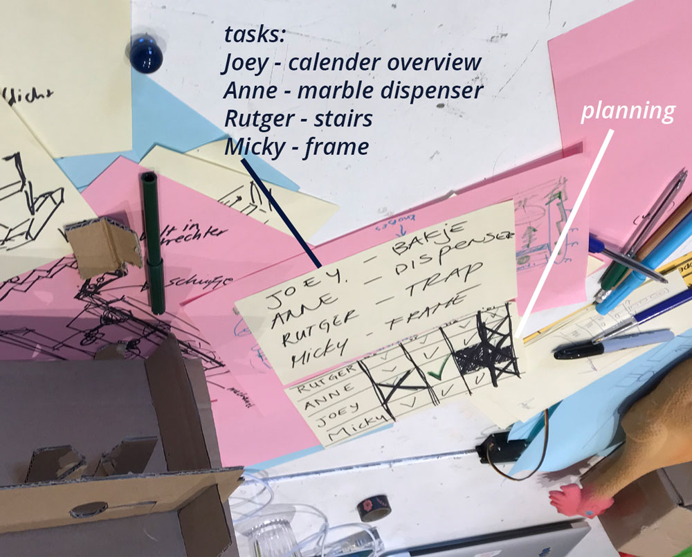
Based on this design we looked at our planning and who has time when. In addition, we divided the machine in parts and we made each person responsible for one parts. This way we work and help out each and we each have an individual task.
- The Marble Calender - Joey: this part represents the booking system with marbles.It shows each half a hour with one marbles. This means it needs enough space for 20 marbles. It kicks out the marbles for the slots that aren’t reserved, so it needs 20 servos one for each marble. It needs a connection to the dispenser and it needs a connection to the stairs.
- The Marble Dispenser - Anne this parts first collects the marbles that come up from the Marble Stairs, so it needs a buckets or sorts for collecting 20 marbles. After that it will roll above the Marble Calender to direct the marbles to each half hour slot. Therefor it needs a connection to the Marble Calender and it needs a ‘rolling system’ to go back an forth.
- The Marble Stairs - Rutger this part brings the marbles that went down back up on top. So it connects the Marble Calender with the Marble Dispenser. It needs a mechanics to move the marbles back on top, it needs a connection to the dispenser, and it needs a connection from the calender.
- The Marble Machine Frame - Micky: this parts connects all the different parts together. It should be stable enough to hold each parts. It should possible to tweak the height of the Marble Calender and the Marble Dispenser to make sure the different connections fit and we keep a certain flexibility in the design. It should have a back frame for the Marble Stairs so the marbles won’t fall off.
 Planning and dividing tasks
Step 5: Prototyping parts of our machine
The next days we each worked on our parts making prototypes and designing each separate part and helped each other whenever someone needed help.
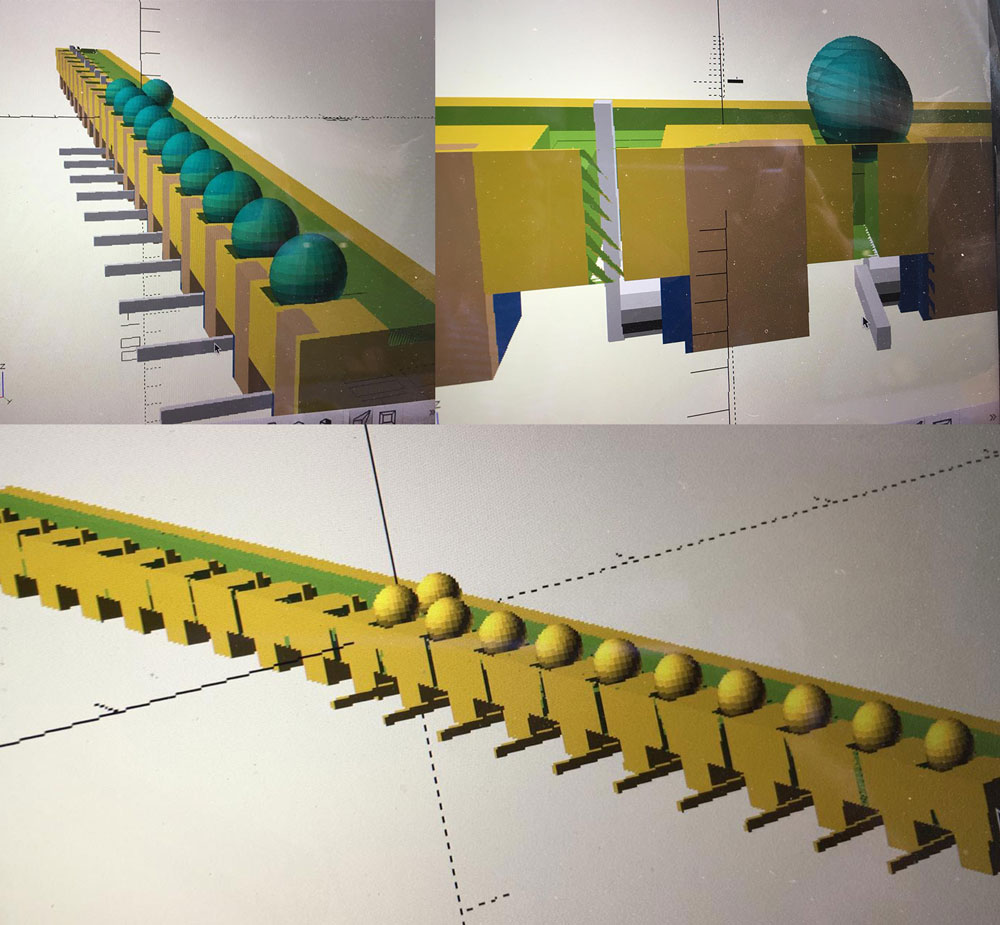
Prototyping the Marble Calender
Joey worked on his prototype for the Marble Calender, first goal was to check the routing and the slots for each marble. He designed the Marble Calender with slots for a marble every half an hour and with 20 servo motors. More details on his ideation, design and build process can be found in his documentation.
 Prototype Marble Calender
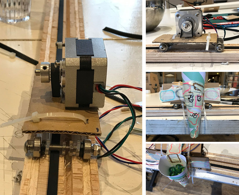
Prototyping the Marble dispenser
Anne worked on the prototype of the Marble dispenser. She first made a design in Fushion 360 and used the Shopbot to make the rails. With some help from Micky she build the car for the dispenser. Together they figured out if the design by Anne would work. Anne further developed and fine-tuned the design of the dispenser. Anne elaborates more on her design process in her documentation
 Prototype Marble Dispenser
Prototyping the Marble stairs
Rutger worked on the prototype of the Marble stairs. The first prototype was a little bit bigger than he thought. So for the second prototype he changed his design a couple of times. The biggest challenge for Rutger was to get the right angle for the marbles to roll over to the next stairs.
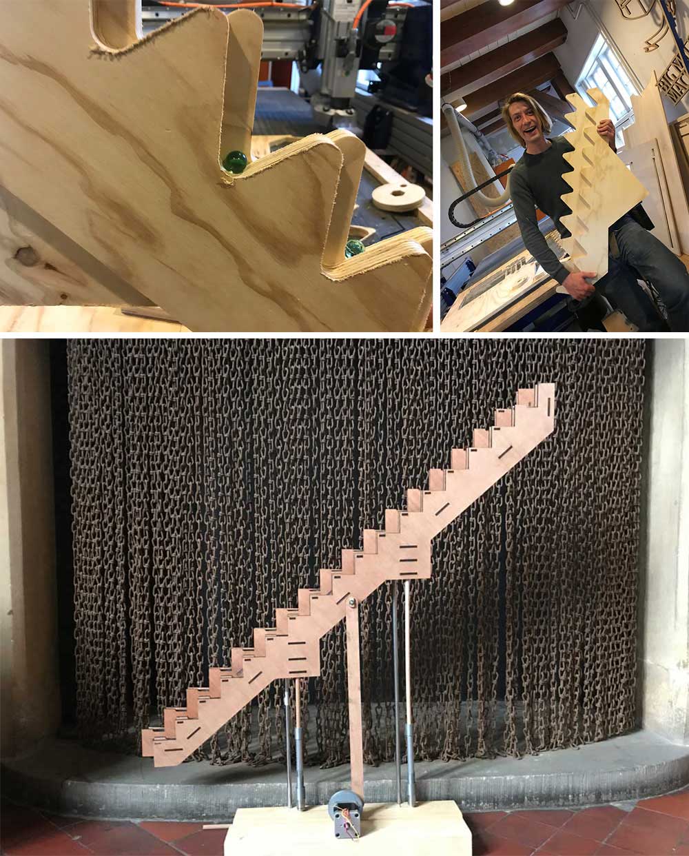 Prototype Marble stairs
Rutger changed the dimensions and design of his stairs. More details on his design and building process can be found in his documentation.
Prototyping the Marble Machine Frame
Micky worked on the prototype of the frame of the machine. First she had to figure out what each of the other members of the team needed so it would fit. Because there was still some uncertainties the frames should be as modular as possible. A more in depth description about the development of the frame can be found in her documentation.
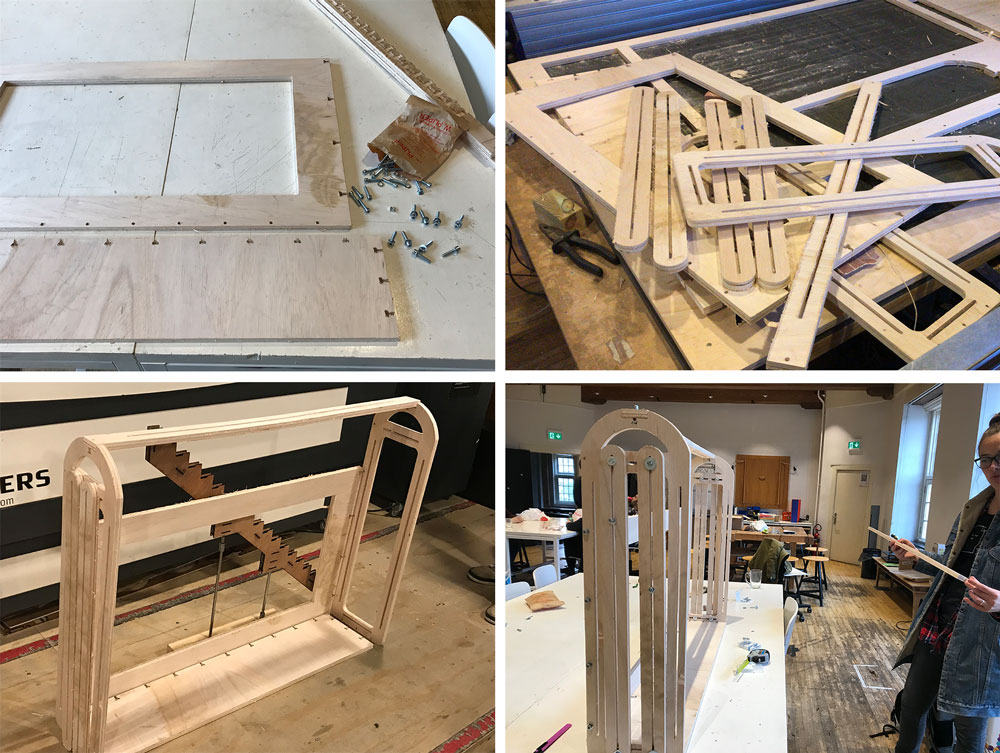 Prototype Marble Machine Frame
Step 6: Connecting parts together
On Wednesday we connected all of the parts together for the first time. This was an important moment because we still didn’t have time to see what the best connection between the pieces would be.
When we had the frame together we could make some new decisions and we realized we had to change some parts.
- Joey has to make the lines and slots a little bit bigger for the marbles to run nicely. There’s a difference in thickness of each marble. However for the smaller marbles his design worked.
- We decided to swap the rails of Anne and Joey, so the marble dispenser will be a marble collector. It collects the marbles from the and brings them to the stairs of Rutger.
- Rutgers stairs drop off the marbles at joey’s calender.
- We still have to make a decision if the stairs will be placed outside or inside the frame.
 End result Marble Machine Frame
The Machine design
For Machine design week, we continued with fine tuning the mechanics of our machine. But mainly we worked on the automation and actuation of the machine. The planning and dividing of tasks was more organic this week. In the beginning of the week Anne and Rutger teamed up to finish the mechanics of the stairs and to automate it. Joey and Micky teamed up to automate and actuate the servos that kick the marbles from their slots. Of course during the week we all helped each other to be able to finish our machine on time.
Step 1: Making the stairs work
One of our main priority for the machine design was to get the stairs to work otherwise the marbles wouldn’t go up.
Fixing the mechanics
In the mechanical week Rutger made different prototypes, but we still had to tweak some parts. Mainly the slope of each step, the mechanics of the movement and the sliders. Rutger explains more about this process in his documentation.
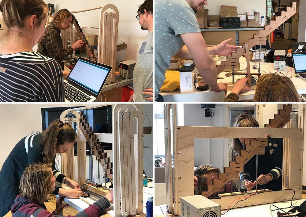 Fine tuning and tweaking the mechanics of the stairs
Testing the mechanics by hand of the new stair design
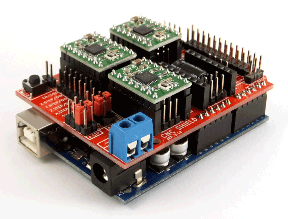
Automating the stairs
We used a stepper motor to move the stairs up and down. Henk showed us the code he used last year and Anne tweaked his code to make it work for the stairs. The code tweaked by Anne, more details on the code can be found in her individual documentation.
#define EN        8      //Negative Enable pin
#define X_DIR     5      //Direction pin
#define X_STP     2     //Step pin

int delayTime=20; //Delay between each pause (uS)
int stps=29000;// Steps to move microsteps 1/32 (200*32 = 6400)
void step(boolean dir, byte dirPin, byte stepperPin, int steps) {

 digitalWrite(dirPin, dir); //

 for (int i = 0; i < steps; i++) {
   digitalWrite(stepperPin, HIGH);
   delayMicroseconds(delayTime);
   digitalWrite(stepperPin, LOW);
   delayMicroseconds(delayTime);
 }
}
void setup(){
 pinMode(X_DIR, OUTPUT); //direction pin = output
 pinMode(X_STP, OUTPUT); //step pin = output
 pinMode(EN, OUTPUT); //negative enable pin  =output
 digitalWrite(EN, LOW); //start negative enable pin at low
}
void loop(){
 step(false, X_DIR, X_STP, stps); //true equals back towards motor
   step(false, X_DIR, X_STP, stps); //true equals back towards motor
       step(false, X_DIR, X_STP, stps); //true equals back towards motor
           step(false, X_DIR, X_STP, stps); //true equals back towards motor
 delay(1000);
 step(true, X_DIR, X_STP, stps); //true equals back towards motor
   step(true, X_DIR, X_STP, stps); //true equals back towards motor
       step(true, X_DIR, X_STP, stps); //true equals back towards motor
           step(true, X_DIR, X_STP, stps); //true equals back towards motor
 delay(1000);

}
To fine-tune the movement of the stairs we had to change amount of steps
Fine tuning the movement of the stairs with the use of a stepper
Step 2: Making the machine booking work
The other big concern for our machine was the representation of our booking system. For this idea we needed to connect 20 servo motors to the main marble run.
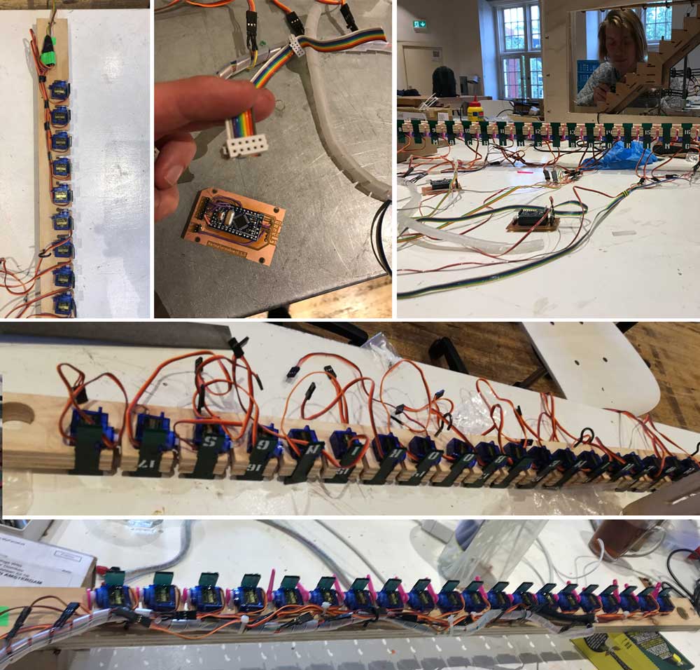 Connecting the servo motors
Automating the servo motors
Joey worked on connecting all the servo motors, he wrote in detail about this process in his individual documentation. We have 20 slots, each slot should be controlled individually by one servo, meaning we need to control 20 servos. To do this we need to connect the servo motors to a PWM pin of the micro controller. Therefore we need to use at least 4 Atmega328 chips, we have these available in the form of Arduino pro minis.
Automating the servo motors
The code to control the servo motors is written by Joey, it controls the servos via serial and it allows the Arduino to address each servo individually.
/*
 *  The Multiple servo controller with Serial controll
 *  This code allows you to controll multiple servos at the same time adressing them by an integer number( 1 between 6),
 *  and tell them to switch state (1 or 0) for open or closed,
 *  using the Serial interface.
 *  The serailEvent handling is borrowed and modified from Tom Igoe serial event example http://www.arduino.cc/en/Tutorial/SerialEvent
 *
 *  http://fab.academany.org/2019/labs/waag/students/josephus-vanderbie//week17.html
 *  made by Joey van der Bie
 *  2019-05-13
 *
 *  This code is based on the Sweep example
 by BARRAGAN <http://barraganstudio.com>
 This example code is in the public domain.

 modified 8 Nov 2013
 by Scott Fitzgerald
 http://www.arduino.cc/en/Tutorial/Sweep
*/
//CHECK OR UPDATE THESE NUMBERS BEFORE UPLOADING!!!!
int ARDUINO_NUMBER = 1; //range 1,2,3 or 4 (Arduino position in servo)
int NUMBER_OF_SERVOS = 5; //number of servo's per Arduino;
//CHECK OR UPDATE THESE NUMBERS BEFORE UPLOADING!!!!

byte servoNumber = B0000000;
byte servoState = B0000000;
byte emptyValue = B1000000; //this is the empty value for our servoNumber and servoState veriables that allows us to check if it is not set.
byte serialProcessBitMask = B00011111;
byte endByte = B11111111;

bool stringComplete = false;  // whether the string is complete


#include <Servo.h>

Servo servo1, servo2, servo3, servo4, servo5, servo6;  // create servo object to control a servo
// twelve servo objects can be created on most boards

int pos = 0;    // variable to store the servo position
int delayTime = 5; // delay between servo steps
int degreeSteps = 1; // steps to take between degrees
int delayBetweenServos = 200; // delay between the movement of servos

int SERVOSTATE_OPEN = 1; //indicator for communication via serial
int SERVOSTATE_CLOSED = 0; //indicator for communication via serial

//default positions (not normally used)
int SERVOSTATE_OPEN_POSITION = 2;//degrees position for open
int SERVOSTATE_CLOSED_POSITION = 95;// degrees position for closed

//The servo structure
struct ServoStruct {
  unsigned int  servoNumber:5; // the number we addres from our serial communication, the :5 is the number of bits used
  unsigned int  pinNumber:4; // the pin it is connected to, the :4 is the number of bits
  int   currentPosition; // current position in degrees
   Servo  servoObject; // the actual object
   int OPEN_POSITION; // open position (anything between 0 and 180)
   int CLOSED_POSITION;// closed position (anything between 0 and 180)
};

struct ServoStruct ss1, ss2, ss3, ss4, ss5, ss6;


void setup() {
  Serial.begin(9600);

  ss1.servoNumber = (ARDUINO_NUMBER-1)*NUMBER_OF_SERVOS + 1;
  ss1.pinNumber = 3;
  ss1.currentPosition = 0;
  ss1.OPEN_POSITION = SERVOSTATE_OPEN_POSITION;
  ss1.CLOSED_POSITION = SERVOSTATE_CLOSED_POSITION;
  ss1.servoObject = servo1;
  ss1.servoObject.attach(ss1.pinNumber);
  ss1.servoObject.write(ss1.OPEN_POSITION); // move the servo to its start position

  ss2.servoNumber = (ARDUINO_NUMBER-1)*NUMBER_OF_SERVOS + 2;
  ss2.pinNumber = 5;
  ss2.currentPosition = 0;
  ss2.OPEN_POSITION = SERVOSTATE_OPEN_POSITION;
  ss2.CLOSED_POSITION = SERVOSTATE_CLOSED_POSITION;
  ss2.servoObject = servo2;
  ss2.servoObject.attach(ss2.pinNumber);
  ss2.servoObject.write(ss2.OPEN_POSITION);

  ss3.servoNumber = (ARDUINO_NUMBER-1)*NUMBER_OF_SERVOS + 3;
  ss3.pinNumber = 6;
  ss3.currentPosition = 0;
  ss3.OPEN_POSITION = SERVOSTATE_OPEN_POSITION;
  ss3.CLOSED_POSITION = SERVOSTATE_CLOSED_POSITION;
  ss3.servoObject = servo3;
  ss3.servoObject.attach(ss3.pinNumber);
  ss3.servoObject.write(ss3.OPEN_POSITION);

  ss4.servoNumber = (ARDUINO_NUMBER-1)*NUMBER_OF_SERVOS + 4;
  ss4.pinNumber = 10;
  ss4.currentPosition = 0;
  ss4.OPEN_POSITION = SERVOSTATE_OPEN_POSITION;
  ss4.CLOSED_POSITION = SERVOSTATE_CLOSED_POSITION;
  ss4.servoObject = servo4;
  ss4.servoObject.attach(ss4.pinNumber);
  ss4.servoObject.write(ss4.OPEN_POSITION);

  ss5.servoNumber = (ARDUINO_NUMBER-1)*NUMBER_OF_SERVOS + 5;
  ss5.pinNumber = 9;
  ss5.currentPosition = 0;
  ss6.OPEN_POSITION = SERVOSTATE_OPEN_POSITION;
  ss6.CLOSED_POSITION = SERVOSTATE_CLOSED_POSITION;
  ss5.servoObject = servo5;
  ss5.servoObject.attach(ss5.pinNumber);
  ss5.servoObject.write(ss5.OPEN_POSITION);

  ss6.servoNumber = (ARDUINO_NUMBER-1)*NUMBER_OF_SERVOS + 6;
  ss6.pinNumber = 11;
  ss6.currentPosition = 0;
  ss6.OPEN_POSITION = SERVOSTATE_OPEN_POSITION;
  ss6.CLOSED_POSITION = SERVOSTATE_CLOSED_POSITION;
  ss6.servoObject = servo6;
  ss6.servoObject.attach(ss6.pinNumber);
  ss6.servoObject.write(ss6.OPEN_POSITION);
}

void loop() {
//  servoToState(1,SERVOSTATE_CLOSED);
  // print the string when a newline arrives:
  if (stringComplete) {
    //Serial.print("number: ");
    //Serial.write((int)servoNumber);
    //Serial.println("");
    //Serial.print("state: ");
    //Serial.write((int)servoState);

    servoToState((int)servoNumber, (int)servoState);
    resetSerialStorageValues();
  }

}

void servoToState(int servoNr, int state){
  if(state == SERVOSTATE_OPEN){
   // state = SERVOSTATE_OPEN_POSITION;
  }else if(state == SERVOSTATE_CLOSED){
   // state = SERVOSTATE_CLOSED_POSITION;
  }else {
    //invalid state, stop the function
        //Serial.print("invalid state:");
        //Serial.println(state, BIN);
        //Serial.println(SERVOSTATE_OPEN, BIN);
        //Serial.println(SERVOSTATE_CLOSED, BIN);
    return;
  }

  if(ss1.servoNumber == servoNr){
    moveServo(&ss1, state?ss1.OPEN_POSITION:ss1.CLOSED_POSITION);
  }else   if(ss2.servoNumber == servoNr){
    moveServo(&ss2,  state?ss2.OPEN_POSITION:ss2.CLOSED_POSITION);
  }else   if(ss3.servoNumber == servoNr){
    moveServo(&ss3,  state?ss3.OPEN_POSITION:ss3.CLOSED_POSITION);
  }else   if(ss4.servoNumber == servoNr){
    moveServo(&ss4,  state?ss4.OPEN_POSITION:ss4.CLOSED_POSITION);
  }else   if(ss5.servoNumber == servoNr){
    moveServo(&ss5,  state?ss5.OPEN_POSITION:ss5.CLOSED_POSITION);
  }else   if(ss6.servoNumber == servoNr){
    moveServo(&ss6,  state?ss6.OPEN_POSITION:ss6.CLOSED_POSITION);
  }else{
      //Serial.print("No servos found for number:");
      //Serial.println(servoNr, BIN);
      //Serial.println(ss1.servoNumber, BIN);
      //Serial.println(ss2.servoNumber, BIN);
      //Serial.println(ss3.servoNumber, BIN);
      //Serial.println(ss4.servoNumber, BIN);
      //Serial.println(ss5.servoNumber, BIN);
      //Serial.println(ss6.servoNumber, BIN);
  }
}

void moveServo(struct ServoStruct *servo, int newPosition){
  //Serial.print("Moving servo");
  //Serial.println(servo->servoNumber);
  if(servo->currentPosition < newPosition){
    for (pos = servo->currentPosition; pos <= newPosition; pos += degreeSteps) { // goes from 0 degrees to 180 degrees
      servo->servoObject.write(pos);
      delay(delayTime);                       // waits 15ms for the servo to reach the position
    }
  }else{
        for (pos = servo->currentPosition; pos >= newPosition; pos -= degreeSteps) { // goes from 0 degrees to 180 degrees
      servo->servoObject.write(pos);
      delay(delayTime);                       // waits 15ms for the servo to reach the position
    }
  }
  servo->currentPosition = newPosition;
}

/*
  SerialEvent occurs whenever a new data comes in the hardware serial RX. This
  routine is run between each time loop() runs, so using delay inside loop can
  delay response. Multiple bytes of data may be available.
*/
void serialEvent() {
  while (Serial.available()) {
    byte incommmingByte = Serial.read();
    if (incommmingByte == endByte) {
      if(servoNumber == emptyValue || servoState == emptyValue){
        //we have missed a crucial value, reset our ledger.
        resetSerialStorageValues();
      }else{
        //everything checks out, lets process the command
        stringComplete = true;
      }
    }else if(servoNumber == emptyValue){
      servoNumber = serialProcessBitMask & incommmingByte;
    }else if(servoState == emptyValue){
      //maks the incomming byte and limit it to one bit (0 or 1);
      servoState =  serialProcessBitMask & incommmingByte;
    }else{
      //something went wrong
      //continue by storing the values, but move them up a place
      servoNumber = servoState;
      servoState = incommmingByte;
    }
  }
}

void resetSerialStorageValues(){
    stringComplete = false;
    servoNumber = emptyValue;
    servoState = emptyValue;
}
Joey explains the parts of his code and the other codes used the automate the machine more in detail in his documentation.
Wiring the servos
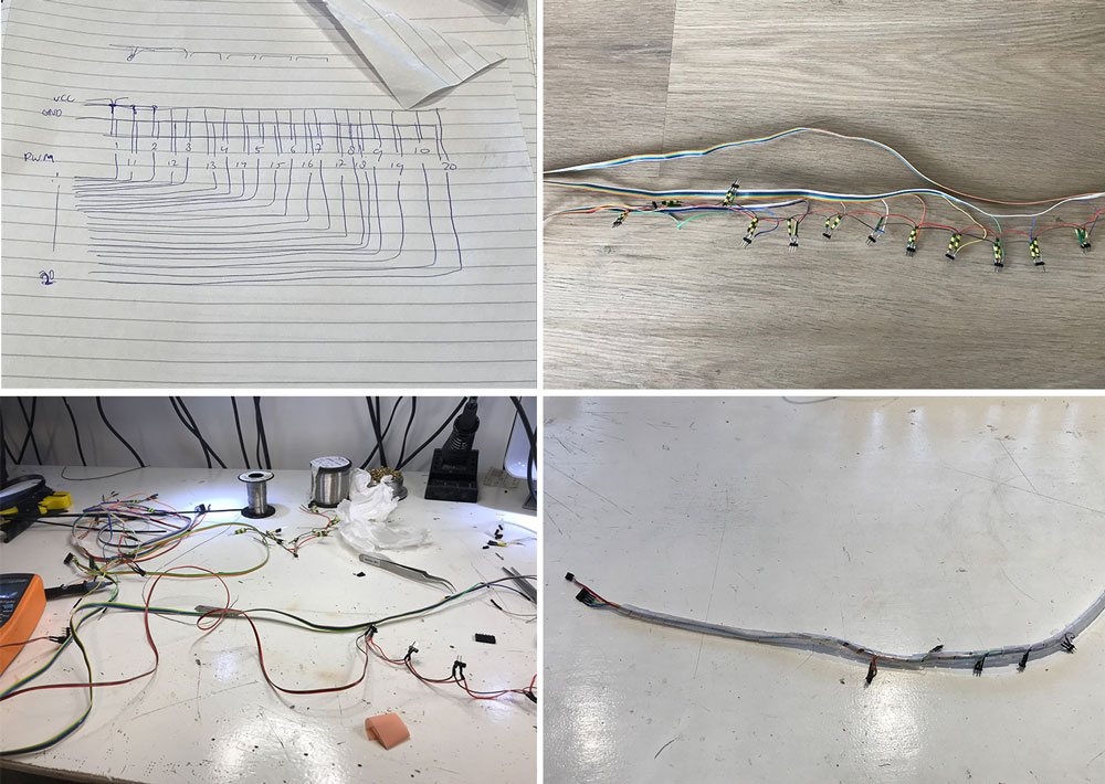 The wiring of our machine
To make sure we could control 20 servos we needed a wire that would connect all the servos to ground, vcc and data. Micky made the cable tree, as can be seen in the drawing on the top right and the result on the top left. However when we connected the wire the servo motors it turned out to be difficult to debug as we had 20 connections in one. Because we have four board with each a connection to five wires.
Fine tuning the servo motors and wiring
Therefore we decided to change the wiring from one cable connected to 20 servo motors to four cables each connected to five servos. Micky redid the cable, more details on the wiring and the cable tree can be found on her documentation.
Step 3: Connecting the parts together
When we had the stairs and calender working separately the next step was to connect the parts together.
- Stairs need to drop off the marble in the calender run.
- After the marbles are kicked out by the servos they need to roll back to the stairs.
- The marble run needs to drop the marble at the stairs.
 Connecting the parts together
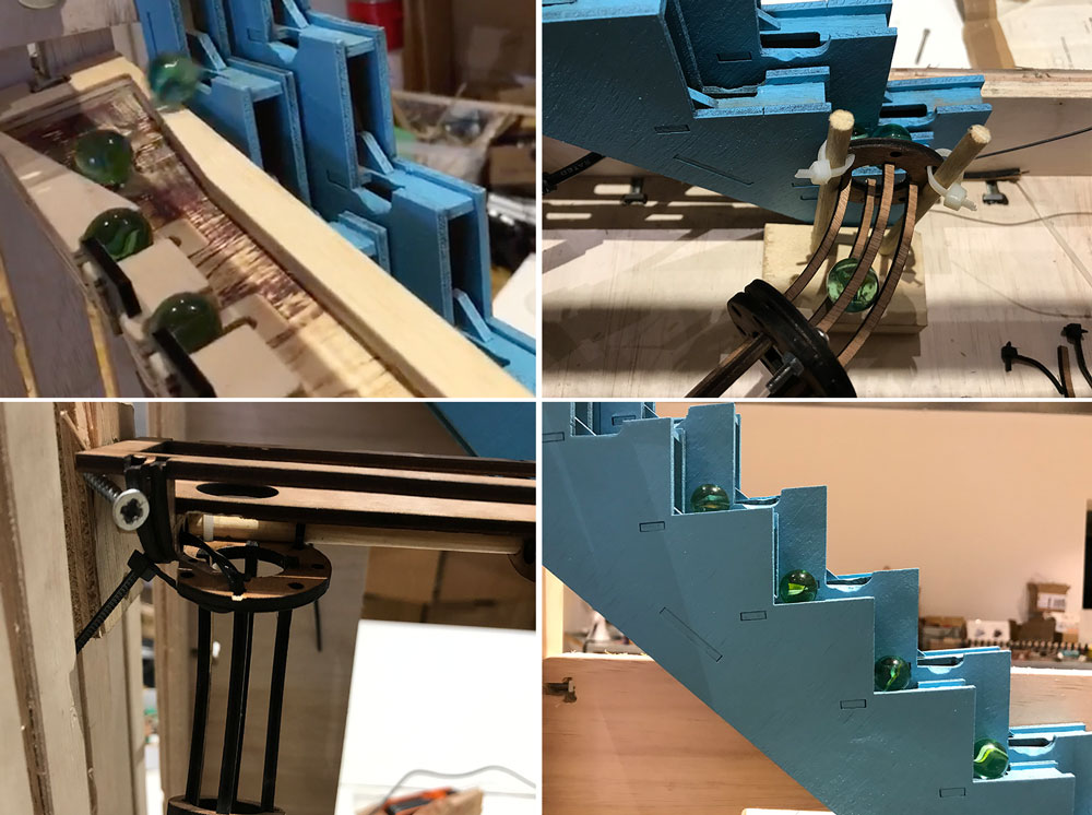
Designing the marble run
To be able to move the marbles back to the stairs and from the stairs to the slot. We had to design the runs for the marbles to go down. Rutger had a lot fun making the runs which connect the marble calender with the stairs, with some loops.
 Marble run
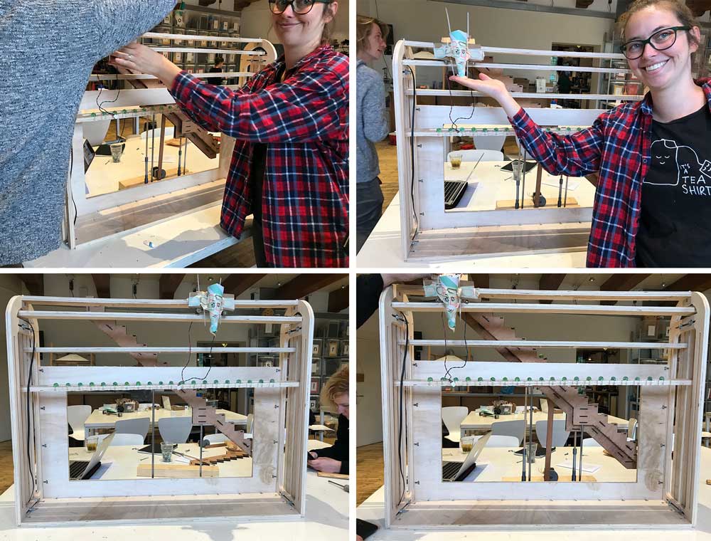
Step 5: Assembling our machine
When we had all the part finished and together the big moment was there to assemble everything and to make the machine. First we had to make sure everything fitted within the frame and the wiring was as need as possible, for the time we have.
 Machine assembly
The next step was to get all the electronics to work. Before we assembles we had it working separately but now it was time to see how each part would work.
Step 6: Powering our machine
The double stairs that bring the marbles from the bottom to the top are attached to the frame. The back stairs are fixed and the front stairs are fixed to the bottom. The bottom stairs is mounted to a plate with two guide rails that allow the stairs to go smoothly up and down. A third rod is threaded that is directly driven using a nema 17 motor. The motor is controlled with a Arduino Uno with Motor shield. All power for the stairs are from a bench power supply (this tells us how much the stairs are using). A better more permanent solution would be a 9V/1A DC power adapter. The Arduino Uno doesn’t get power from the Motor shield so it can be powered with a central power line connecting all Arduino boards (5v).
 Marble run
Losing our marbles
We managed to pull off a lot in just two weeks and we’re very proud of the end result. However for the next time we do have so things we would like to change and improve for version 2.0.
- Material: We are currently using a combination of a lot of different materials, this makes it look a bit messy. Limiting the kinds of materials and colors would be better. For the marble track acrylic would look a lot better!
- Electronics: We spend a lot of time on all the wiring, cables and we designed some boards. The wires are sometimes a bit too short. They could be hidden slightly better. And the PCBs and connections are really fragile. And the boards still have a few mistakes in them. For version two of this machine it would be great to design custom PCB’s for this machine and have them ordered from China. This way we can also improve our power management.
- Design: It’s not at all clear yet what the machine communicates: availability of the machines in the lab. This can be improved with more emphasis on the ‘calendar’.
- Construction: Due to material availability in the lab we have long parts that tend to bend in the middle (servo beam & first track). This could be improved with a better choice of material and a improved design