After 18 weeks working on my final project, I had most of the parts covered. However, there were still some more things to make and test. One of those things is the case where the electronics and the Battery is kept in safe. The other one is the support for the BLDC motor and finally, I had to design and test the pulley for the motor. You are probably asking why I leaved those steps until now, the answer is that simple, I was not sure of the result, and I knew that I would need many iterations before having a working prototype. I have learn from this experience some nice fact about how to calculate the diameter of the belt that you are going to use depending of the pulleys, or how to design an HTD-5 pulley

The 3D Design of the motor support was initially made in one piece. When I printed some prototypes, it gave me some interesting feedback.
My first design, was too big, and it was inspired by a commercial support, but the other ones, have been started from scratch (scratch is in this case the pdf of the blueprint of my BLDCs motors),
to finally adopt a two piece design, which is very useful,
and work great, but that is at the same time a solution that is much more fragile than the first one.
The shape of the middle part, is specific to my longboard and to the position (angle) I thought was better for the Longboard, it is for this reason, that if you want to change it,
you have to take care of to change this core, which is very complicated, so have fun!
Download Here The Motor Support 3D Files

As I mentioned before, the process of designing the support, has been a try and error process because basically there is many things to take in count, as for example that if the nut is not inside the support, the support will be to large, and it will touch the pulley of the wheel, or for example that if it is only in one piece, it will be impossible to make the support fit with the truck because at the beginning, the truck has a larger shape, so it will be difficult to try to put the support on the truck with your hand without broking it (it happened to me with the aluminium one made with the Modela). For the case, the first test was a failure but because we didn't print the good file, but when we sent the good one, the battery didn't fit nether because the angle of the borders was too small. So at the end, we basically sent the exact same case but without the angle (so 90 degrees extrusion). For the motor pulley, we tried with different sizes and shapes until finding one, that could have at least 5 teeth making the traction and that is not too large to do not cover the screws that helps you tens the belt.

After trying with 20% of PLA, solid PLA (100% infill), we found that the PLA was not strong enough, and the problem with milling as we did with a previous prototype, is that now that the whole support, is more complex, so the SRP Player said that the whole process (2 big parts of the support, and 2 small parts) took around 114 hours. This amount of time could be ok if we had an automatic coolant tool but because we don't, we have to have care and be spraying W40 because otherwise, it would represent a killed end-mill and possibly a fire camp. Finally, we decided to work with the Mojo which works with ABS and that has a very good finish because believe it or not, we change the hot-end each time we change the filament, so basically, the result is a solid, very nice looking Support.

After two and a 1/20 (the small one to check the design) of case, I knew that it had to be the last one because it is a lot of filament each time I print a case (it is very big, the last one is 380mm*157mm*45mm).
It is for this reason that I decided to make all the details and to do not wait the case to make holes and things like that. So basically this case has one hole in each side where the BLDCs cable will go through, a hole in one lateral side for the charging port,
and finally small holes at the top to screw the cover to the case (as well as some hole at the base to screw the case to the board). And after all those changes, it was time to send it to the Sigmax and see what happens.
Here you can see the the cover, but we will not print it, it is useless to print something that has not really 3d shapes, so what I did is export the cover blueprint as a PDF, and use an online converter from pdf to DXF and Laser cut it.
I will join you the 3d design, the pdf and the DXF.
Case 3D-Design
Cover DXF
Cover PDF
PDF to DXF Converter

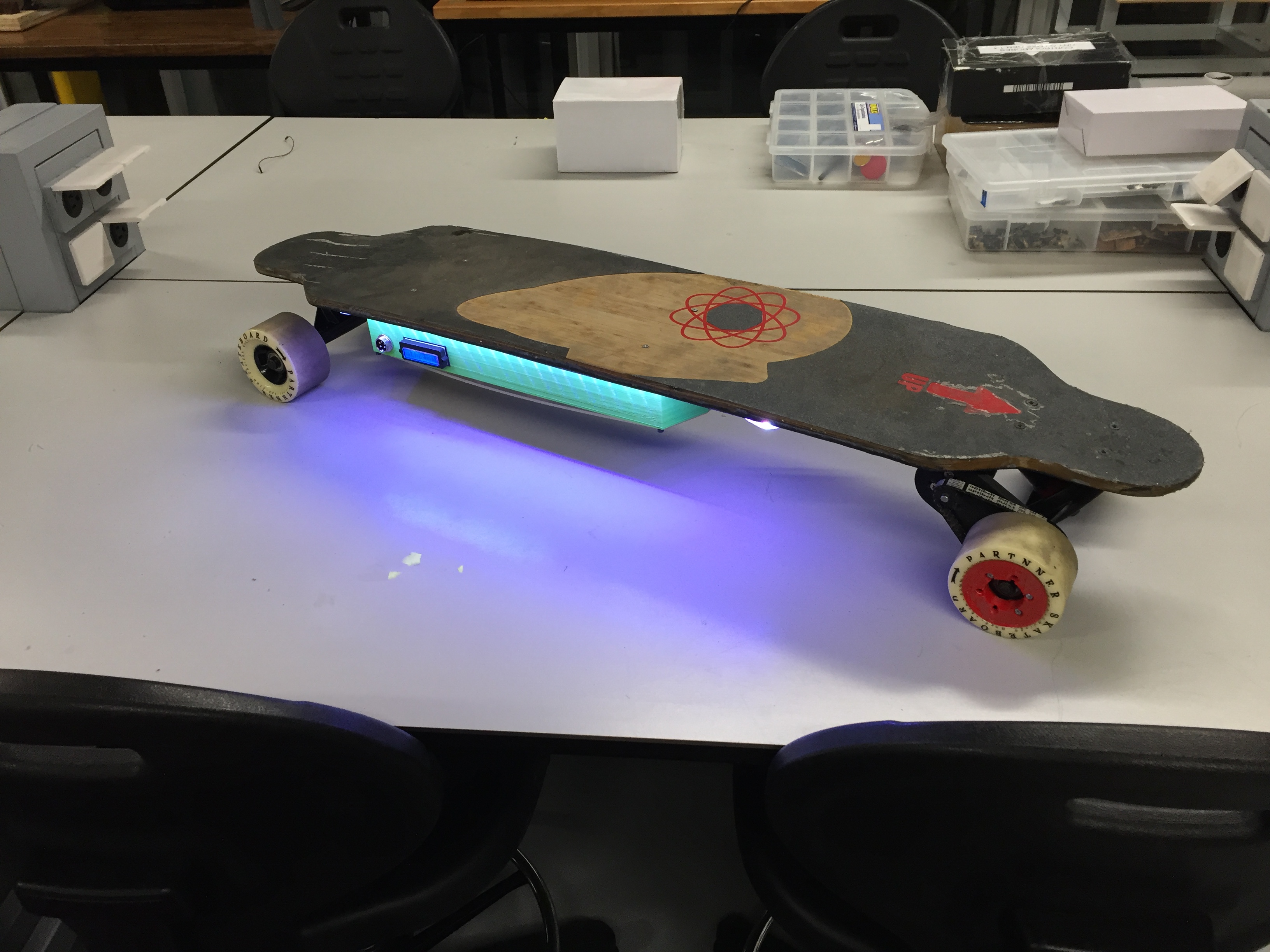
After 28 hours printing in the SIGMAX which is the biggest printer that we have in the lab, it is ready. The color looks exactly as I wanted, Flashy. The only small problem, is that the magnets of the heated bed, was not stick very well, and the it caused some irregularities in some points of the case, but nothing very important, I will probably have to sand some parts. I placed the two big parts of my electronics in the case, and it seems that everything fits very well, we will not have to print it again. The infill that we used is 35% and really it looks very strong.

As you all know, I am doing an electric Longboard with two BLDC motors. Those motors can work with a charge of up to 70Amps and a voltage of 8S which is around 21.6V because 1S (1S = 1LiPo cell in series which is 3.6V). But because I didn't knew a lot about Brushless motors, I bought this motor without really knowing if they were going to be useful for me, I just saw that its size looks appropriate. After checking, I understood that depending of your needs, you can need speed or torque and if you need torque, you will need less kv which is rpm for one volt (around 180-250 kv for longboards) and more (430 kv as mine for example) if you need speed and not a lot of torque. In my case, it was better to have torque because in Peru we have some hills, but at this moment I didn't knew that. However, as you know a brushless motor need an Electric Speed Controller, which in my case is a 6S - 80Amps ESC. The reason why I chose a 6S ESC, is because 430kv is too much, and using a 6S, I am limiting the RPM, and with the speed controlling (PWM SIGNAL), I can control even more the speed (I can limit is very easily in Blynk, limiting the output value from 1000 to 1500 instead of 2000 for example). The current of my ESC is 80Amps, and it can lead with peaks of up to 120 amps. But really, because of the 6S - 40Amps, the max current will be 40 Amps with peaks of up to 60Amps. The reason why I bought a 40Amps BMS, is because after that, the price becomes too expensive so for the moments I will limit the current and use an acceleration ramp to limit the amount of current ask to the BMS when accelerating the first time.

As you can see, I decided to use this shape of battery pack because it is much slimmer and can fit very well in the case. The materials I used for the battery pack are those:
Batteries
Bullet Connectors
Nickel Strips
Electrical Insulating Adhesive Paper
Double Battery Holder
PVC Heat Shrink Wrap
12 AWG Silicone Wire
6 Pin DIN Connector
6S - 40Amps BMS

The connections followed to connect the BMS to the batteries are basically the one previously showed. But now let's try to understand better the theory behind the batteries. The datasheet says that the continuous discharge current for one battery is 20Amps, so with 3 in parallel, we are talking of 60Amps and 9000mAh because for both values, we have to add those values depending of the amount of batteries in parallel. For the voltage, we can calculate it multiplying the voltage of one of the cell, by the amount of batteries in series. As you can see, I added a heat shrink tube around the BMS to protect it as much as possible of the heat produced by the batteries for example (and also the batteries of the heat produced by the BMS).

As showed in the Schematic, I am using two nickel strips for the series connection and one for the parallel connections. Those kind of batteries, can receive serious damages if soldered with a simple hot iron, it is for this reason, that we have to use a spot welder, which produces a lot of heat but for a very small amount of time to solder the nickel strips to the batteries. To solder it, you first have to test it on cheap batteries to know how much amps to use, and how much force you need to apply when soldering it because otherwise you will damage the battery and the nickel strip will not be soldered well enough.

This part of the work, has been completely new to me but by chance, the FabLab team had some experience working with that (Special Thank to Alvaro Mendivil) and they gave me all the know-how to be able to have a successful mechanics. I had to buy a belt for my projects, which is the htd-5 which mean that it has a pitch of 5mm but really that was define since the first day because of my wheel pulley. But realLy there were two more things to know, the diameter of the belt, and the number of teeth of the motor pulley. The online tool that I used says that we have to have at least always 6 teeth in contact with the belt, but in my case because a bigger one would not let me screw the motor to the support when trying to tense the belt, I will have to only have 5 teeth in contact with the belt. With this config, I am having as a result, a 13 teeth motor pulley and a 295mm belt of 9mm of width. I bought the exact belt from Optibelt which is a German Brand that is a bit expensive but that has a very good quality. The screenshot that you are looking at, has my own parameters.

Now that we have the number of teeth (13) and the kind of belt that we are going to use, we have to design the pulley, which is really not easy if we want to make something precise. For this reason, I searched and find this very nice tutorial , that this you how to do the exact same Pulley in Fusion 360. In this tutorial, we can also find an excel with all the info to continue with the tutorial based on the number of teeth and the kind of belt that we are using. The most important information in this excel, is the outside diameter of the pulley (19.55mm in my case).

The 3D Design has two important parts, the one made with the previously showed tutorial, and the hole to put the captive screw and make sure that the motor will make the necessary traction between the motor and the wheel.
For this part, I basically leaved a hole to put a nut inside, and another to put the captive screw. I don't know why but only a lot of time later, I imagine why I didn't simply make the hole for the motor axis with the same shape, and leaved the captive screw but only to make sure,
that the pulley doesn't move back and forth. The design works, but please don't 3D print it because it is a head ache to remove the support from the hole and to put the nut inside. In a future, I will definitely mill it in aluminium to make it mechanically stronger and easier to replace.
Here you can find the 3D Design of the Pulley
You can download the ZIP files with everything here or download them individually.
For the code, it is better to look into week 15 assignment.
BLDC Support part 1.1
BLDC Support part 1.2
BLDC Support part 2.1
BLDC Support part 2.2
Wheel Pulley
Exterior wheel Pulley (optional) - Print 2 in mirror mode
Motor Pulley
Case
Case Cover
Grip Design to Cut
Longboard Logo for Vinyl Cutter
Up Design for Vinyl Cutter
Mold part1
Mold part2
Board Sketch File
Board Brd File
BOM - Prices
Here you can see my final project presentation:
Please Contact Me For Any Collaborative Project