Week 14
-
NETWORKING AND COMMUNICATIONS
Group Assignment
The partners on this group assignment are:
- Silvia Lugo
- Diego Santa Cruz
- Ivan Callupe
- Carlos Nina (Me)
The goal at the group assignment was connect two boards, the first one with a button (Diego's board, on the rigth) and other with a LED (my board, on the left). the communication was made via serial communication.
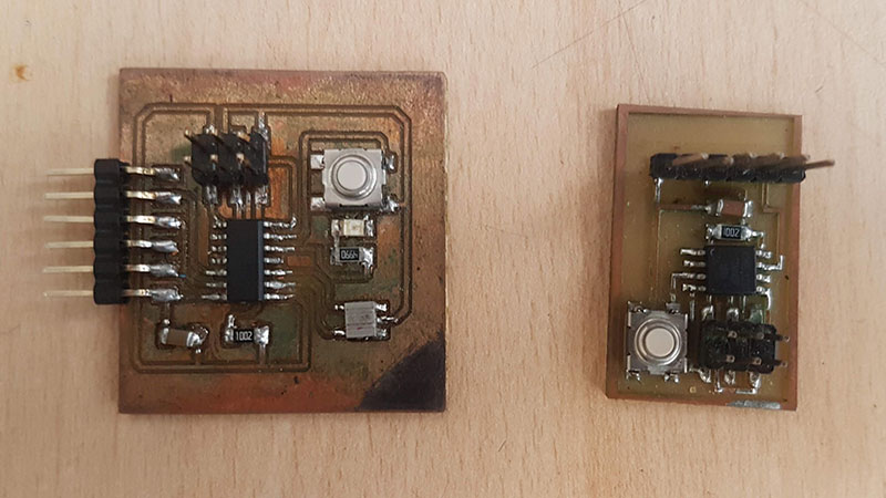
The LED board, has an Attinny44, the button board has an Attinny45. Due to only the Attiny 45 has the built-in hardware for serial communications, we had to establish it by software.
The code for the button boards is this. We use a library "SoftwareSerial.h" to create the communication.
Button board code
          #include < SoftwareSerial.h> //remove the space between < and SoftwareSerial.h

          int rx = 1;    //Declares the RX pin
          int tx = 2;    //Declares the TX pin

          SoftwareSerial mySerial(rx, tx);  //Setting up the RX/TX pins as a SoftwareSerial

          char button = 4;//Declares the character that represents the virtual button current state

          void setup(){
            mySerial.begin(9600);       //Start the serial communication and select the its speed that deppends of the frequency that it will be program the attiny

            pinMode(button, INPUT);      //Configures the BUTTON pin as an input

          }

          void loop() {

              if (digitalRead(button) == HIGH) {         // Condition For LED on

                mySerial.println("1");         //Prints in the screen the actual state

              }
              else if (digitalRead(button) == LOW) {      // Condition For LED off

                mySerial.println("0");         //Prints in the screen the actual state

              }

          }
(*If you use de code, please remove the blank space before _SoftwareSerial.h. I include this to show the name properly).
LED board code
            #include < SoftwareSerial.h> //remove the space between < and SoftwareSerial.h

            int rx = 0;    //Declares the RX pin
            int tx = 1;    //Declares the TX pin

            SoftwareSerial mySerial(rx, tx);  //Setting up the RX/TX pins as a SoftwareSerial

            char buttonState = '1';//Declares the character that represents the virtual button current state
            char lastButtonState = '0'; //Declares the character that represents the virtual button last state
            int ledPin = 8;     //Declares the pin where the indicator LED is already attached


            void setup(){
              mySerial.begin(9600);       //Start the serial communication and select the its speed that
            				//deppends of the frequency that it will be program the attiny

              pinMode(ledPin, OUTPUT);      //Configures the LED pin as an output
            }

            void loop() {

              buttonState = mySerial.read();    //Reads the message a "1" or a "0" from the command line

              if (buttonState != lastButtonState) {   //Checks if there exist a change in the virtual button state

                if (buttonState == '1') {         // Condition For Motor ON

                  mySerial.println("ON");         //Prints in the screen the actual state
                  digitalWrite(ledPin, HIGH);     //Turns ON the indicator LED


                }
                else if (buttonState == '0'){      // Condition For Motor OFF

                  mySerial.println("OFF");         //Prints in the screen the actual state
                  digitalWrite(ledPin, LOW);       //Turns OFF the indicator LED
                }

                delay(50);
              }

              lastButtonState = buttonState;        //Sets the current state as a last state

            }
(*If you use de code, please remove the blank space before _SoftwareSerial.h. I include this to show the name properly).
To load the program to the boards, we used Arduino IDE, to do that, we had to install the new boards to the Arduino IDE, this process is described on my assignemnet on week 7 (electronics design).
If you are familiar with the procedure, you can use this url, to get the new board to arduino IDE.
https://raw.githubusercontent.com/damellis/attiny/ide-1.6.x-boards-manager/package_damellis_attiny_index.json
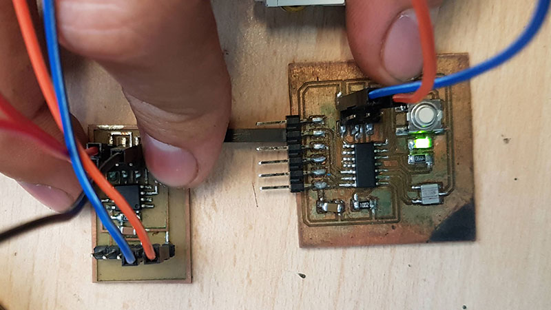
Finally. After load the progrmas and connect the boards. We could turn on the LED of one board via a serial communication of a button from another board.
INDIVIDUAL ASSIGNMENT
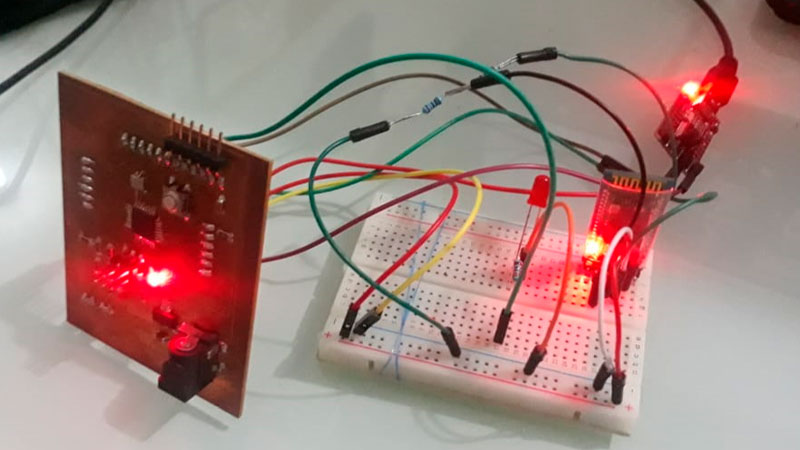
This week I started control a Fabduino via Bluetooth to turn on a LED. This is important, because I will going to use this setting on my final project, but with servos instead of LEDs.
The connection is this. I used a FTDI adapter to feed mi Fabduino. and a modelue HC-05 to connect via serial communication the Fabduino and my Android phone.
Due to this week is about communication, the process of the design of the mobile app (with MIT APP Inventor), will be described on the week 16 (Interface and Application Programming).
But, I have to say, for the first test with serial communication via bluetooth, I used an App called "BT Terminal Free", thanks a recommendation of my partner Abdon Troche, who helps me a lot with this assignment.
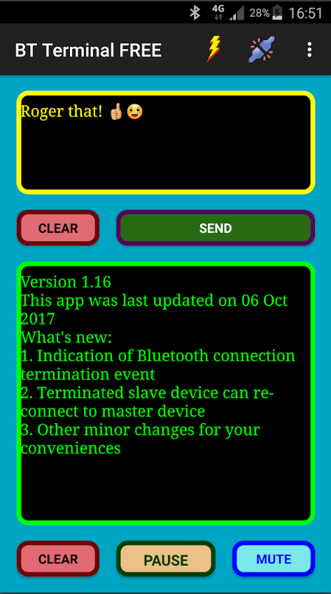
(Taken from the App website).
The code I used, to turn on the led, via a serial communication between the mobile app and the Fabduino is this:
            #include

            #define RxD 10
            #define TxD 11

            #define DEBUG_ENABLED  1

            SoftwareSerial blueToothSerial(RxD,TxD);

            int led_matrix = 8;

            void setupBlueToothConnection(){

              blueToothSerial.begin(9600); //Set BluetoothBee BaudRate to default baud rate 38400
              blueToothSerial.print("\r\n+STWMOD=0\r\n"); //set the bluetooth work in slave mode
              blueToothSerial.print("\r\n+STNA=HC-05\r\n"); //set the bluetooth name as "HC-05"
              blueToothSerial.print("\r\n+STOAUT=1\r\n"); // Permit Paired device to connect me
              blueToothSerial.print("\r\n+STAUTO=0\r\n"); // Auto-connection should be forbidden here

              delay(2000); // This delay is required.
              //blueToothSerial.print("\r\n+INQ=1\r\n"); //make the slave bluetooth inquirable
              blueToothSerial.print("bluetooth connected!\n");

              delay(2000); // This delay is required.
              blueToothSerial.flush();

            }


            void setup(){

              pinMode(RxD, INPUT);
              pinMode(TxD, OUTPUT);

              setupBlueToothConnection();

              pinMode(led_matrix,OUTPUT);
              digitalWrite(led_matrix,LOW);

            }

            void loop(){

              char recived_char;
              char last_recived_char;


              while(1){

                //check if there's any data sent from the remote bluetooth shield
                if(blueToothSerial.available()){

                  recived_char = blueToothSerial.read();

                  if( recived_char == '1' ){

                    digitalWrite(led_matrix,HIGH);
                    last_recived_char = recived_char;

                  }
                  else if( recived_char == '0' ){

                      digitalWrite(led_matrix,LOW);
                      last_recived_char = recived_char;

                  }

                }

              }

            }
"
Finally, I could turn on the LED with an android app via serial communication.
Files of this assignment:
<<< Go to Week 13 assignment | >>> Go to Week 15 assignments