Week 11
-
INPUT DEVICES
Group Assignment
Measure the analog levels and digital signals in an input device.
Individual Assignment
Measure something: add a sensor to a microcontroller board that you have designed and read it.
GROUP ASSIGNMENT
This week, the group assignment is well documented on the page of Abdon Troche in this link.
Measure of angle (INDIVIDUAL ASSIGNMENT)
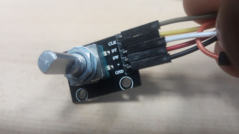
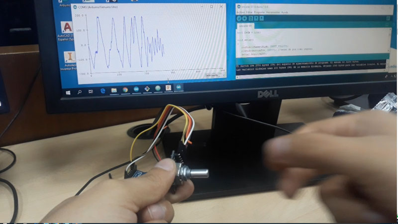
This week, I wanted to measure angle positions with a encoder and a board made by myself. This is a rotary encoder that I could get. This have 20 pulses by revolution and is very cheap.
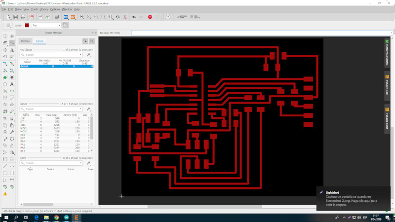
After read lots of tutorials, I finally figured out how to design the board. This circuit includes a Attiny44, the connections to an FTDI communication and the ports needed to program it.
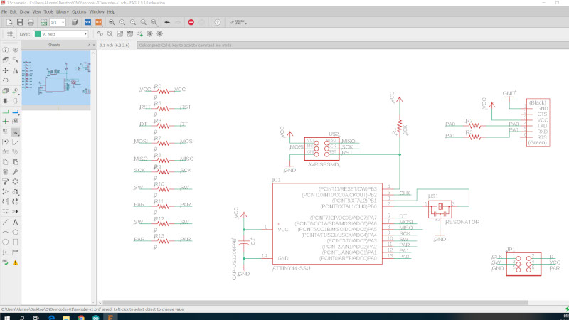
The next image, shows part of the schematic design and the connection with the encoder.
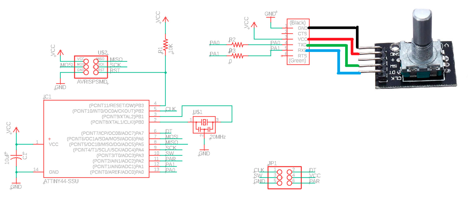
The schematic has to be modified, to include resistors of 0 Ohm, due to mi board needs a lot of bridges.
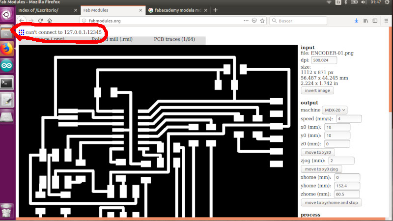
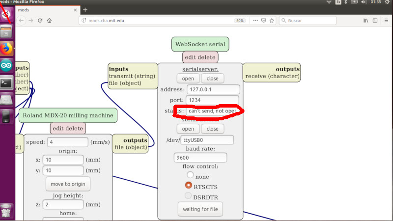
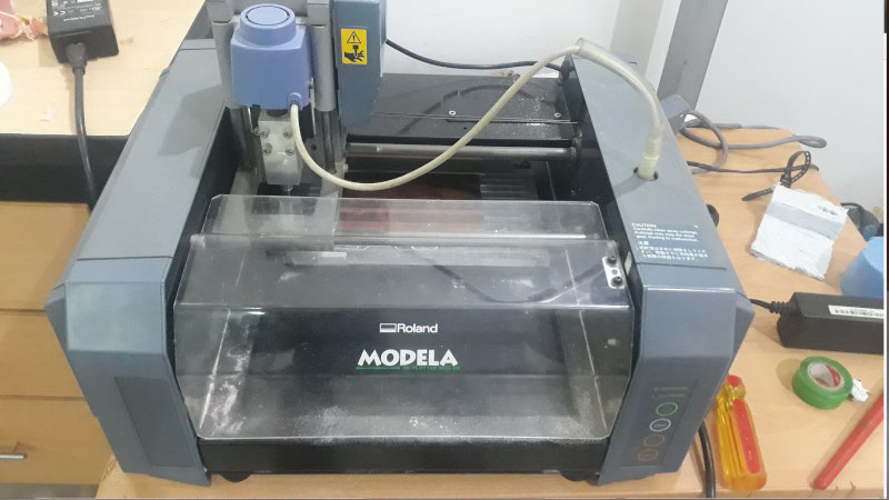
Unfortunately, I couldn't connect the Modela MDX-20 with the PC. At this moment is too late to ask someone. even with mods, I was no able to mill my board. Well. I will find the solution to make my board next week.
It was really disappointing. But, I could work on the software until my board finally can be milled.
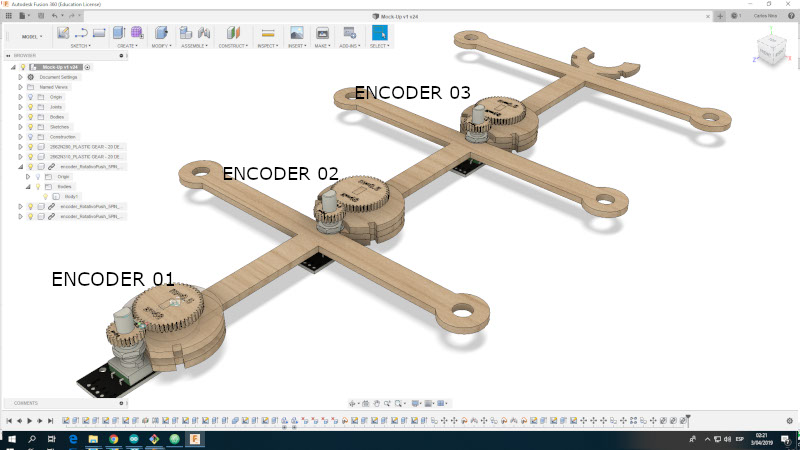
The next step is build a mockup to my final project. This way I can try read the angles with the encoder and later control the actuator to align again the parts.
I don't want to waste time. So, I write a sketch to read the angles. Due to I don't have my board yet, i used an Arduino. (I know, I know... is just for the moment. I will make my board as soon as possible).
The code looks like this:
const int channelPinA = 2;
const int channelPinB = 3;
const int buttonPin = 9; // boton de reseteo

const int timeThreshold = 5;
long timeCounter = 0;

const int maxSteps = 41;
volatile int ISRCounter = 20;// inicia la cuenta a la mitad
int counter = 20; // inicia la cuenta a la mitad
int buttonState = HIGH; //estado de boton de reseteo

bool IsCW = true;

void setup()
{
   pinMode(channelPinA, INPUT_PULLUP);
   pinMode(buttonPin, INPUT); //seteo de pin como ingreso
   Serial.begin(9600);
   attachInterrupt(digitalPinToInterrupt(channelPinA), doEncodeA, CHANGE);
   attachInterrupt(digitalPinToInterrupt(channelPinB), doEncodeB, CHANGE);
}

void loop()
{
   if (counter != ISRCounter)
   {
      counter = ISRCounter;
      Serial.println((counter-20)*9);
   }
   delay(100);

   buttonState = digitalRead(buttonPin);
   if (buttonState != HIGH) {
    // resetea el conteo
    //Serial.println("press");
    ISRCounter = 20;

  }
}

void doEncodeA()
{
   if (millis() > timeCounter + timeThreshold)
   {
      if (digitalRead(channelPinA) == digitalRead(channelPinB))
      {
         IsCW = true;
         if (ISRCounter + 1 <= maxSteps) ISRCounter++;
      }
      else
      {
         IsCW = false;
         if (ISRCounter - 1 > 0) ISRCounter--;
      }
      timeCounter = millis();
   }
}

void doEncodeB()
{
   if (millis() > timeCounter + timeThreshold)
   {
      if (digitalRead(channelPinA) != digitalRead(channelPinB))
      {
         IsCW = true;
         if (ISRCounter + 1 <= maxSteps) ISRCounter++;
      }
      else
      {
         IsCW = false;
         if (ISRCounter - 1 > 0) ISRCounter--;
      }
      timeCounter = millis();
   }
}
Finally, this program works like this.
UPDATE
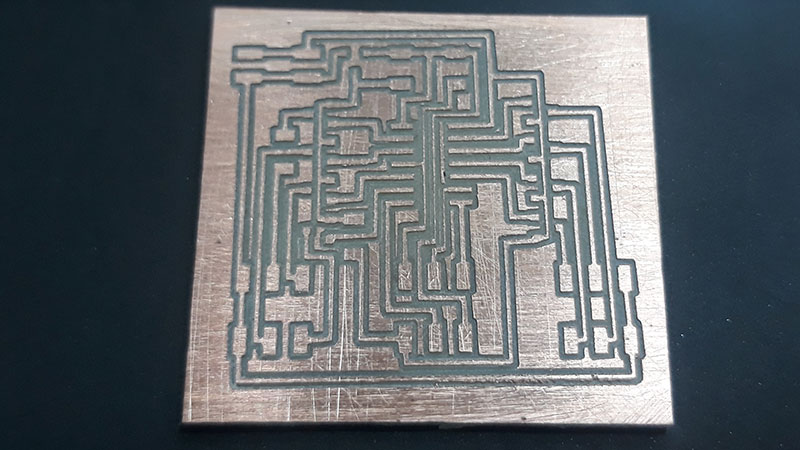
Once, I was able to use the CNC machine, I could make my board. The PCB milled looked like this.
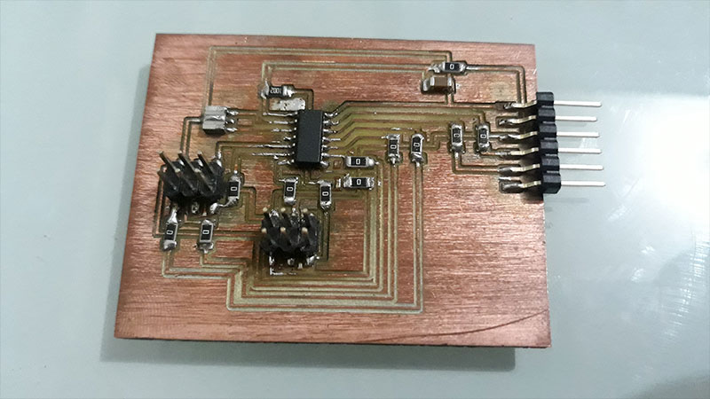
After that, I soldered the components to the board. But, due to this design you have many zero resistors, it was a lot of work (at least for me, a mechanic guy :).
Later, I tried to use mi previous code, but I noticed that mi use of interrupts was not adecuate for an Attiny44. So, I changed the code based on many sources, and learning so much in the process.
The goal of this code is fade a LED (conected to pin PA7), according the value of the rotation of the encoder. At the beginnings I tried to connect the LED to the pin PA3, but the LED didn't fade. Later, I found on Google, that I was using the wrong pin. Fade a LED require an PWM pin. I had to search into the datasheet to ensure pins with PWM enabled.
Finally the code is this:
            #include "avr/interrupt.h"

            #define LED  7
            #define wheelA 0
            #define wheelB 1

            bool previousB = false;
            volatile int portReading = 0;
            volatile int value = 50;
            volatile bool update = true;
            int brightness = 0;    // how bright the LED is


            void setup() {

              pinMode(LED, OUTPUT);          //PWM LED output
              pinMode(wheelA, INPUT_PULLUP); //Inputs for rotary channels
              pinMode(wheelB, INPUT_PULLUP);

              GIMSK = 0b01000000; //turn on pin change (Page 47 Datasheet)
              PCMSK0 = 0b00000011; //turn on interrupts for pin 13 (PCINT0) and 12 (PCINT1) (Page 48 Datasheet)
              sei(); //turn interrupts on
            }

            void loop() {

              if (update) {
                update = false;

                brightness = brightness + value; //Up to 255;
                analogWrite(LED, brightness);
                delay(1000);

              }
            }

            /* Pin change interrupt vector */
            ISR (PCINT0_vect) {

              //read the port quickly, masking out other pins
              portReading = PINA & 01;

              //read channel A
              if ( (portReading & (1 << wheelA)) == 0) {

                //determine what part of the waveform we are on
                if (previousB)
                  value++;
                else
                  value--;
              } else {
                if (previousB)
                  value--;
                else
                  value++;
              }

              //record b channel for use next time round
              previousB = (portReading & (1 << wheelB)) == 0;

              update = true; //tell the main loop that a rotation has happened

            }
And the result is this:
It was a very interesting week.
Files of this assignment:
<<< Go to Week 10 assignment | >>> Go to Week 12 assignments