Week 5: Electronics Production
02/19/2019 - Stéphane Muller
This week, the group assignment is to characterize the design rules for our PCB production process. Which means characterizing our milling machine. Then, individually, we have to make an in-circuit programmer by milling the PCB, program it, then optionally, trying other processes.
Check out the documentation for our group assignment.
Initially I wanted to make the FabISP with a mini USB port, but we didn't have all the components so I went for the classic version instead and decided that I would be doing the other version later.
I've had a previous experience in soldering SMD components, let's see if I still got it.
Research
Neil said we didn't have to understand how the FabISP worked exactly (at least not yet), but I like it better when I understand exactly what I'm doing and why, so I did a little digging.
- Great documentation on how the FabISP works
- Super duper YouTube channel on Electronics
- Step by step documentation describing the whole process of milling a PCB with an SRM-20
Planning and list of tasks
- Generating the configuration files with mods
- Milling the PCB
- Soldering the components
- Programming the board
Step by step
Generating the configuration files with mods
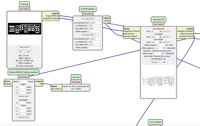
First thing I needed to do was generate 2 files for the SRM-20 to mill the circuit and then the outline. To do that I used mods. Mods is an app that works with nodes, like antimony. There are a lot of different programs on the app and I used the one for the SMR-20.
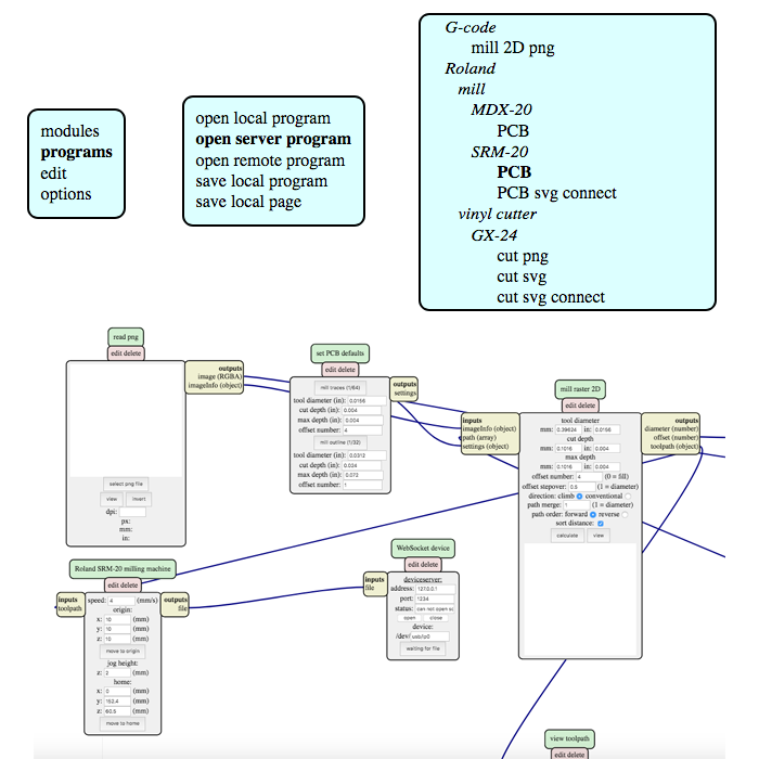
By default there is no module to save the generated files because it's sent directly to the machine. Our machine however, is not connected to the local network so I had to add a module to be able to save the generated files.
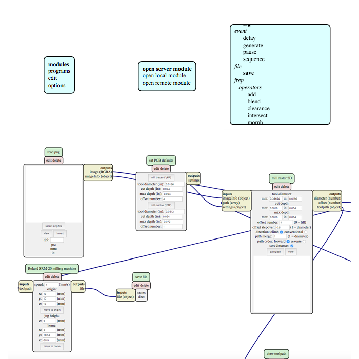
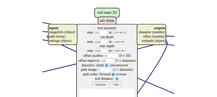
I then customized the settings to the V-shaped mill I was going to use. You can set the tool's diameter in mm and inches, the cut depth and the max depth. All those are pretty straightforward. Then there's the offset number, which is the numer of passes the mill is going to make. And the offset stepover, which is the percentage of overlap after each pass.
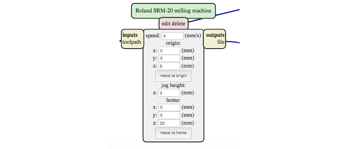
Then we need to set the advance speed. I changed it to 3 mm/s because that's the speed with which we had the best results during our group assignment. Then there's the origin coordinates and the home coordinates. For the home coordinates it's important to have the z coordinate be greater than 0. Otherwise you'll end up with a nice scratch in the middle of the board...
The global view of the mods looks like that.
Milling the PCB
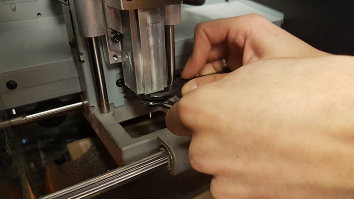
I started by using double-sided tape to fix the copper plate to the sacrificial board. Then I changed the mill. You have to be careful not to screw the mill too hard when you do it, otherwise you might damage the mill.
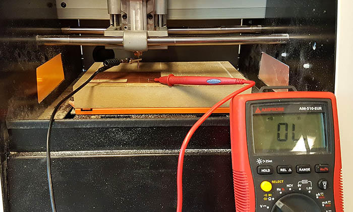
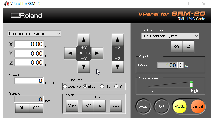
The x and y origins are easy to make. Just place the mill at the bottom left of your board (or the place where you want to mill) and click on the X/Y button under "Set origin point". To set the z origin it's a little trickier though. Since the mills are very thin they're also very fragile. So we need to lower the mill very carefully and very slowly, with steps of 100, then 10 and finally 1 micron. And to know when the mill touches the board, you need to use a multimeter. One end needs to be wired to the mill and the other to the board. As soon as the multimeter beeps, you know the mill touches the board.
Once that is done, I just warmed up the mill by having it run freely for 5 minutes by clicking on ON. Then I clicked on "Cut", which opens up a window to import the g-code file generated with mods and launched the cut!
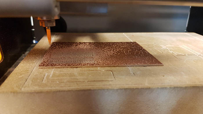
Since we broke the only straight mill we had in the lab during the group assignment, I had to use a V-shaped mill. Unfortunately, the settings were off and I ended up with lots of thin copper traces between the paths. This traces could potentially create shorts. So instead of generating a new g-code with mods and import it again, I edited the file myself. I replaced the "-3" with "-4" to mill a little deeper and restarted the milling. Since I didn't change the x, y and z origins, the mill would just make another pass on the circuit, but a little deeper.
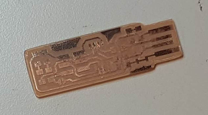
The second mill didn't do the trick... There were still unwanted traces of copper that could potentially create short circuits. So this time I went back into mods and changed the offset stepover from 0.5 to 0.7. The result still wasn't perfect, but it was better and I just had to clean it a bit with a cutter. I also sanded it quickly with very thin grain and cleaned it with acetone. Now, on to soldering!
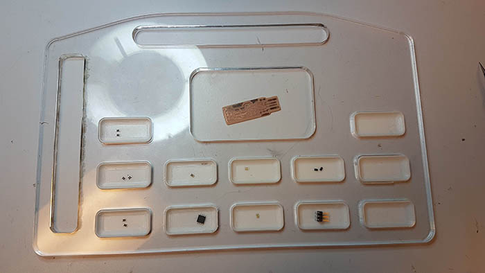
Soldering the components
I went shopping in the lab for the necessary components, set up my soldering station and got started. I set the solder iron to 380°C and used a fine tip with very thin tin.
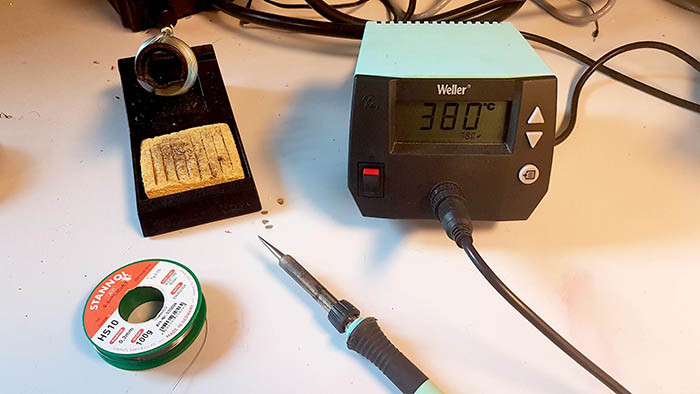
As I said, I already had a little experience with soldering so I managed quite easily. I started with the smallest components and ended with the ISP pins and the ATTiny. I did like Neil said, put some solder on the board where the component was supposed to go, used it as a glue to fix it, soldered the other side and finally went back to the first bit. I still had it it! I'm glad it went so smoothly because the last time I soldered something in the lab, the solder wouldn't melt and I thought I was doing it wrong.
The iron has to be clean to work properly! If the solder doesn't stick or behave like it should, use flux.
And here is the final result. The solder is shiny everywhere, although maybe not the smoothest.
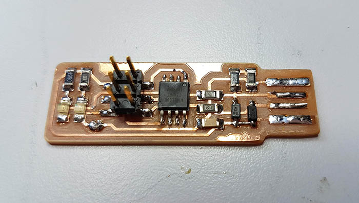
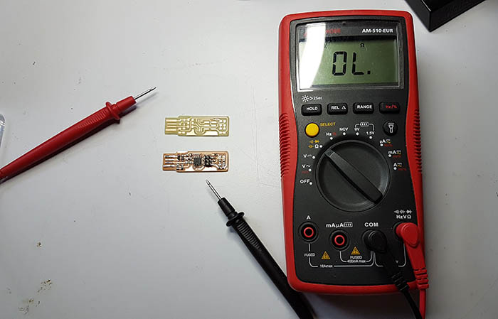
I checked my connections and soldering with a multimeter to see if the parts that were supposed to be connected still were and those who weren't supposed to really weren't. I should have done that before soldering as well actually... but I forgot. I used another blank circuit we had chemically made in another lab at the university for reference. And sure enough there were 2 places where I needed to add some solder and clean up.
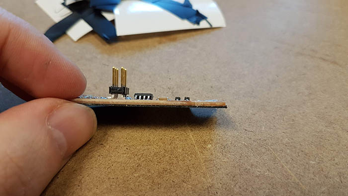
Before I could go on to the next step, I still needed to make the PCB a little thicker to plug it snuggly in the USB port. So to add some thickness I pasted 7 layers of vinyl to it. That did the trick perfectly!
Programming the board
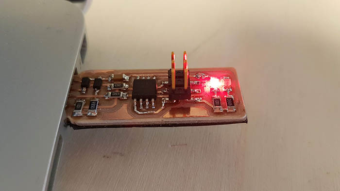
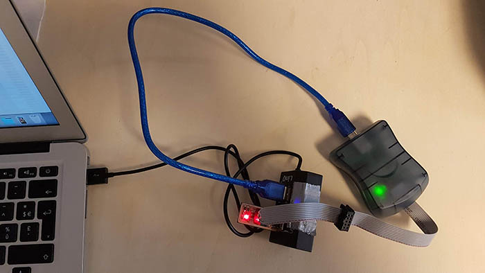
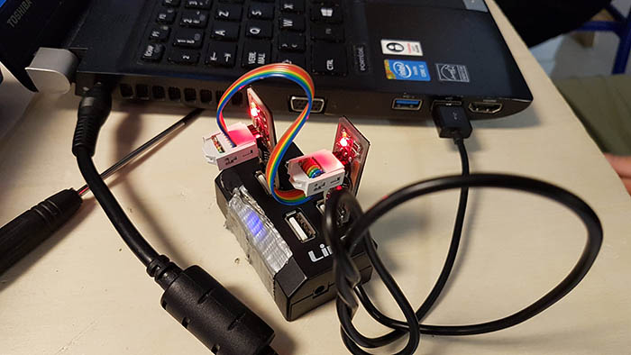
The first test I had to make was check that the red LED went on when I plugged the ISP to my computer. And it worked! So then I used another AVR programmer to send the program to my board. Since I have a USB 3.0 port and it's been known to generate problems, I used a USB 2.0 hub and plugged everything to it, like so.
Next thing I had to do was install CrossPack for Mac and do a "make" to generate the hex file that would be sent to the board.
$ make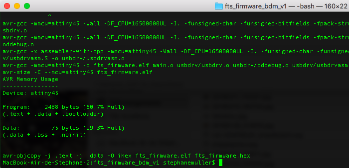
Then I updated the Makefile with the right AVR programmer and flashed the ATTiny with the contents of the hex file.
PROGRAMMER ?= avrisp2$ make flash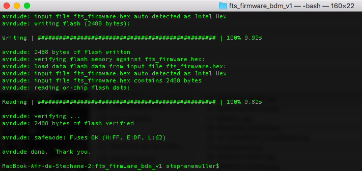
Everything went smoothly... no errors, no bugs. So I kept going and set up the fuses.
$ make fuses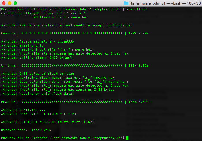
I then had to check the USB functionality of my board. So I plugged it in and checked if it was recognized by my computer and lo and behold... it was! I started to get a little suspicious. Something will go wrong eventually...
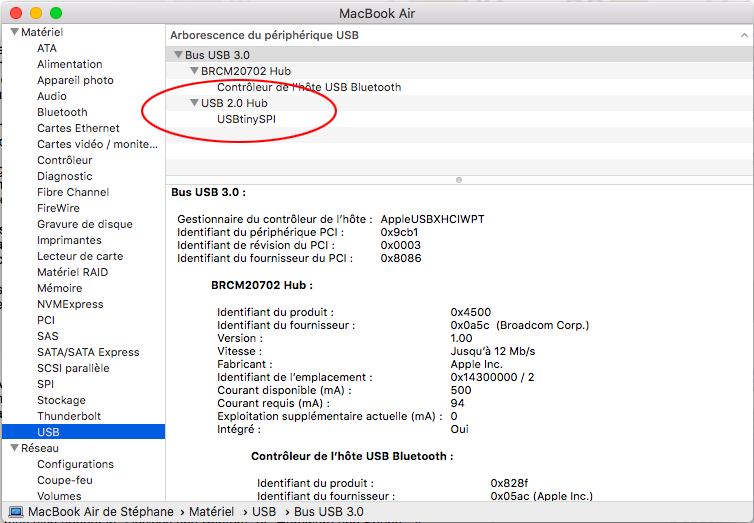
Everything seemed to be working thus far... so I disabled the ability to reprogram the ATTiny by doing the last command.
$ make rstdisbl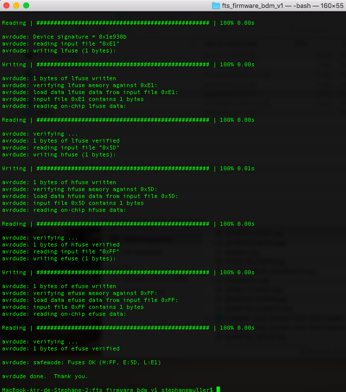
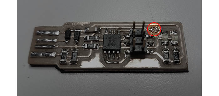
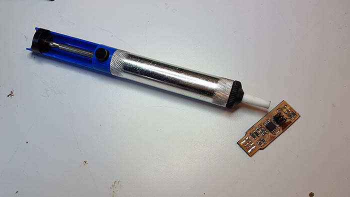
Final thing was then to remove the solder jumper, which I did using a special tool that sucks the solder.
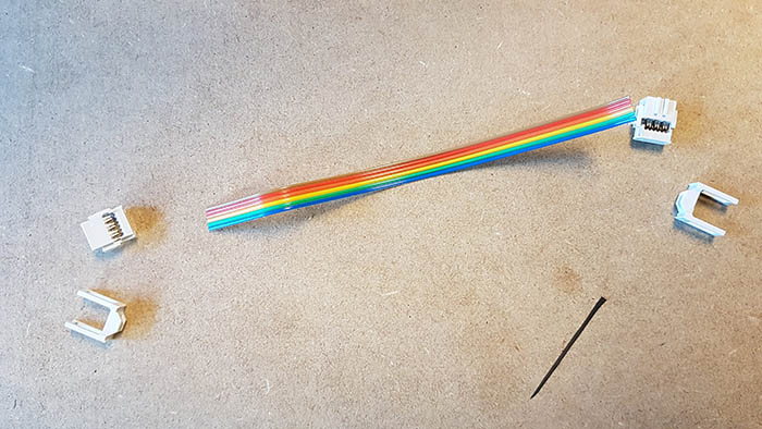
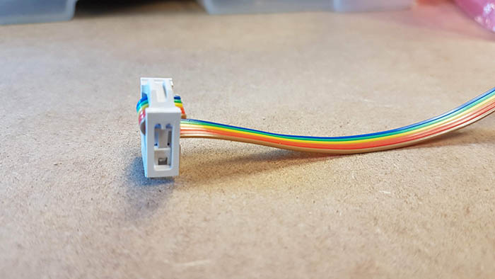
To connect the ISP to another device I needed a ribbon cable so I made one like so.
We used my FabISP to program Leo's FabISP and the transfer worked! Although it seemed Leo's FabISP needed fixing because it wasn't recognized by the computer. But the transfer worked fine!
Conclusion
Challenges
I thought the hardest and most annoying part would be the soldering, when actually it was the milling. But it should be a lot easier with a straight mill next time.
Achievements
I was afraid I would spend hours looking for short circuits or re-soldering components but I'm very proud to say everything went really smoothly! I think I owe this to the checks I made with the multimeter after soldering.
I'm starting to enjoy electronics! I have noted a couple of things that could be improved on the FabISP though and maybe I'll work on it later. First, once the FabISP is programmed and you've removed the jumper, the red LED doesn't go on anymore. At first I thought it was broken and looked for bugs for half an hour... Then there's the issue of USB 3.0. It would be nice to update the ISP so that it works smoothly with USB 3.0. I have to check if the issue is electronics design or programming. And finally I would like to use a micro or mini USB port.