Week 6: 3D printing and scanning
02/12/2019 - Stéphane Muller
As a group we have to test the design rules for our printer(s). And individually we have to design and 3D print an object (small, few cm3, limited by printer time) that could not be made subtractively and 3D scan an object (and optionally print it).
I have wanted to do 3D printing in a long time but never got to actually do it. So this week will be a lot of fun for me! I can't wait to hold my first print in my hands.
Research and inspiration
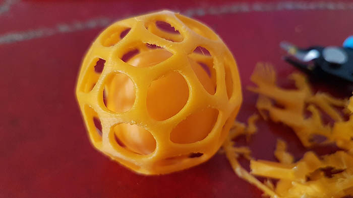
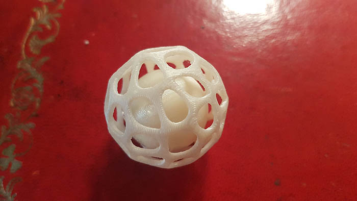
As I was looking for inspiration for my 3D print this week I stumbled upon an interesting geometry, something that came up numerous times: shapes with a voronoi pattern. I like the randomness of the pattern. And to complicate things a little bit for the printer and make a shape that could never be produced otherwise, I thought I would nest another volume it. So why not make a ball with a voronoi pattern that has another full ball inside of it!
During the computer-controlled cutting review two weeks ago, Vaibhav from Vigyan Ashram showcased a beautiful creation made with Rhino and Grasshopper and it got me intrigued. The combination of those 2 softwares seemed very powerful and I love the visual representation of the algorithm in Grasshopper, which is like Antimony. So I thought, why not give it a try!
The most interesting ressources for this week:
- Introduction to FDM 3D printing
- The RepRap wiki
- How to design parts for FDM 3D Printing
- A new test model from AutoCAD
Planning and list of tasks
- Testing the design rules of our printer
- Modeling my object in Rhino and Grasshopper
- Printing my object
- Scaning an object
Step by step
Testing the design rules of our printer
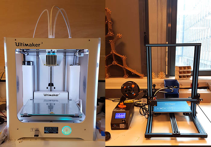
We have 2 printers at the lab: an Ultimaker 3 (on the left) and a CR-10S (on the right).
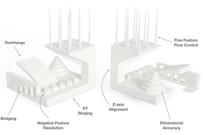
We decided to test the Ultimaker 3 by printing the new model from Autodesk and Kickstarter, which tests a great number of characteristics.
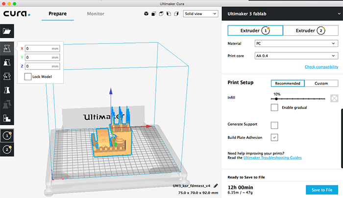
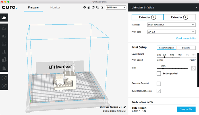
We thought it would be interesting to compare the quality of the print depending on the material used. So we printed the same object with the same recommended settings on Cura with PC (polycarbonate) and PLA (polylactic acid). The print took 12 hours with PC and 11 hours with PLA.
The first thing we noticed is that the PLA print is a lot sharper, cleaner and smoother than the PC one. Now let's review each characteristic one by one.
| Characteristic | PC (polycarbonate) | PLA (polylactic acid) |
|---|---|---|
| Overhangs | Pretty clean up until 20° and still acceptable at 15° | Very clean up until 30° and only slightly messy after, even at 15° |
| Bridging | Quite bad, lots of filament, even for small distances | Barely any filament, with only a couple of bendy filaments |
| Negative feature resolution | Messy and rough | Very clean |
| XY ringing | Only nested cylinder came off, at 0.5 mm offset | 3 nested cylinders came off, the tolerance goes up to 0.3 mm |
| Z-axis alignment | A little jagged, rough | Perfectly straight |
| Dimensional accuracy | There’s a 0.05 to 0.2 mm tolerance. The smaller the dimension, the bigger the tolerance. | There's a 0.03 to 0.1 mm tolerance. The smaller the dimension, the bigger the tolerance. |
| Fine feature flow control | A lot of filaments, not very accurate | Some spiky filaments but quite accurate |


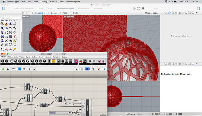
Modeling in Rhino and Grasshopper
My comrade Leo gave me a quick tour of Rhino first and then I started looking at some tutorials for Grasshopper. I watched a series of video tutorials made by the creator of the app and then looked for a tutorial about 3D voronoi patterns in Grasshopper.
The first one I found was very detailed and got me on the right track, but it explained how to apply a voronoi pattern to a flat UV projection and then morph it on another more complex one. Unfortunately, the projection of the pattern on a sphere looked horrible and the seams didn’t align.
So I did a little more digging and found this video. With no explanations however, so I had to search for each tool and tried to replicate what the person had done. But it didn’t work and I couldn’t figure out why. I had downloaded the right plugin (Weaverbird), used all the right components… nothing.
Fortunately, I found some help on the Grasshopper forum, where someone posted a working file that did exactly what I wanted. I did not copy/paste the algorithm though, but tried to understand it. In his file he used a facet dome component which is not a voronoi diagram, so I used what I had learned (and worked) from the other video and combined it with his approach.
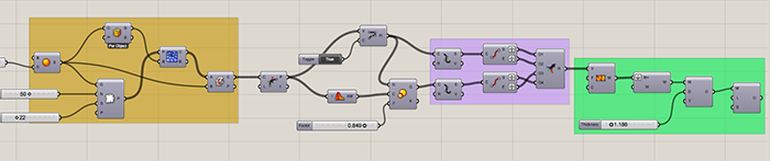
Here is the whole algorithm and how it works:
-
First part (in orange)
- Create a sphere
- Populate the surface of the sphere with randomly dispersed points
- Create a voronoi pattern from those points (this will create a series of surfaces originating from the center of the sphere going outwards, but bound by a box)
- Get the intersection between the surface of the sphere and the surface of the 3D voronoi pattern
- Find all discontinuities in the curves produced by the intersection (that will give us the intersection points)
- Create straight lines from those points (what we had earlier were curves) and close them
- Get the average centers of all the points
- Scale the points down centered around the average center
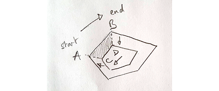
- Divide the lines of the original pattern and the scaled down pattern into segments and then extract the end points of those segments
- We now have a list of start points and end points of a list of segments which we want to convert into faces… so we’re going to combine them (merge them) into a list of sets of 4 points. Each set of 4 points is a quad face we want to turn into a mesh. Which is why the second set (coming from the scaled down points) is inverted, so that the points are given in the right order.
- Then construct the mesh from those 4 points faces
- Join the meshes and weld them together
- Give the mesh some thickness
- And finally subdivide the mesh to smooth the edges
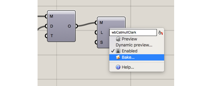
Here comes the tricky part (in purple)
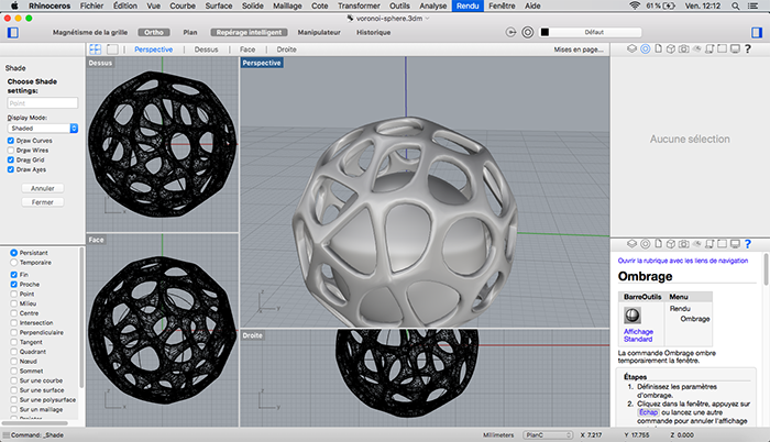
Designs generated in Grasshopper are virtual at first so when you’re done you have to “bake” them to actually create them in Rhino.
I added the sphere inside and “voilà”!
Printing my object
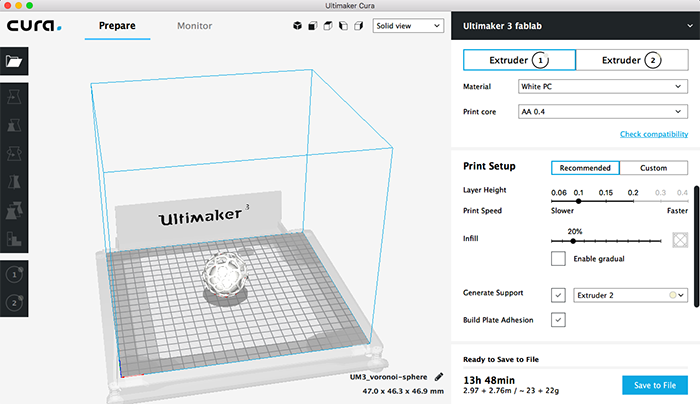
I wanted to print on our Ultimaker 3 printer, so I downloaded the latest version of Cura. Cura is a slicer, it takes a 3D model and slices it into very thin layers. These layers are then put into g-code and sent to the printer.
The interface is very user-friendly and the settings pretty straightforward. For my first print I decided to go with recommended settings. For materials I set up the printer to use polycarbonate for the main print and PVA for the support. PVA dissolves in water, which is very practical for the support, especially when the print is as complex as mine, with areas I wouldn’t be able to access after. My print was supposed to last 14 hours but since I was planning on leaving it for the weekend, I wasn’t bothering anyone.
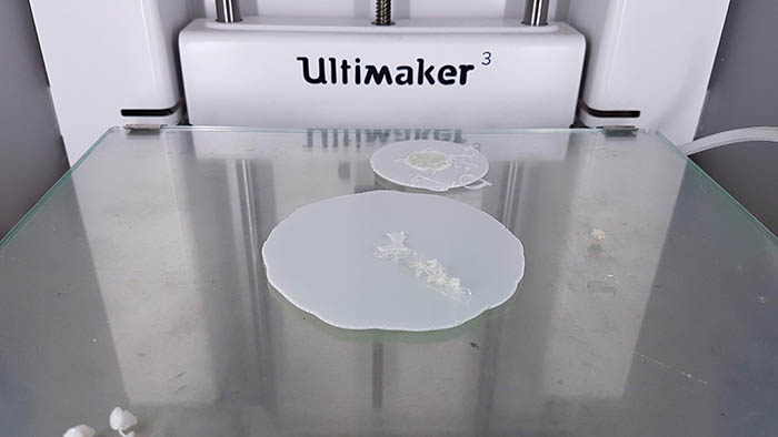
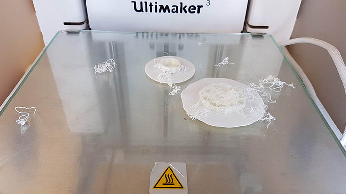
The printer gave me the following warning “Set of printcores not calibrated…”. But I decided to ignore it and print anyway. The printer did something a little unusual so one of my colleagues paused it. It was printing in the center of the plate (like it should) and also one the top right corner… We thought it was going to print the sphere in half or that the 2 extruders were completely offset (like waaaaaaaay offset).
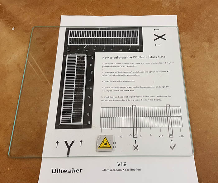
So on Monday I did an x-y offset calibration like it was described in the printer’s documentation. What it does is print 2 grids with each extruder to compare to a diagram to determine the offset of each axis. Then you input the offset in the printer. Unfortunately, the offset was 0 for both axis...
So I launched the print again (with lower settings this time to have a shorter print)... and it failed again. It did the same thing as last time, only I decided to let it finish. But fate would not have it so. The print got disconnected from the plate and stopped.
At this point I asked Adel for help. He thought it was due to my version of Cura, so we opened my model in an older version of the software. That’s where we noticed a small shadow on the virtual plate when we enabled the second extruder (for the PVA support). Adel explained that this could be due to the fact that extruder cleaned its head before switching. As a matter of fact, polycarbonate needs to be heated at a higher temperature than the PVA.
Because we thought the problem was linked to Cura and my model, Julie took that time to launch her print. She ran into problems as well… her print wasn’t adhering to the plate either. She retried a couple of times, adding glue to the plate and eventually switching from polycarbonate to PLA. The latter did the trick.
The next morning I launched my print on the Ultimaker 3 and on the CR-10S (just to be sure). On the CR-10S I specified supports but only on the plate and on the Ultimaker 3 I used PVA supports everywhere. Both prints worked this time!

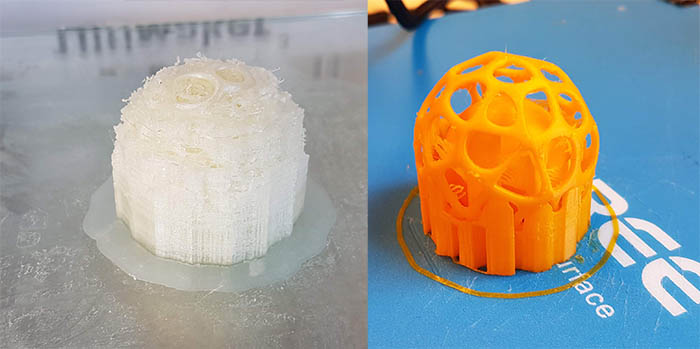
I removed the support from the CR-10S print with cutting pliers and then sanded it.
As for the Ultimaker 3 print, I put it in warm water for a couple of hours, to let the PVA dissolve.
Scanning an object
I have to say I didn't find scanning very appealing at first. The handheld scan we had at the lab didn't seem to produce great results and neither did VisualSFM. But I didn't have time to do the scan during the week, so I got to see what my comrade Leo did first and I was very impressed with the result he got with Meshroom. I decided to try it as well!
Meshroom uses photogrammetry to get measurements and depths from multiple photographs of an object or scene. It creates a cloud of points in 3D and is able to use these informations to produce one or more 3D meshes from it.
What's a bit frustrating with this software is that, even though it's opensource, it's only available for Windows (and Linux) AND computers equipped with nvidia graphic cards... Which I don't have. Fortunately, I could use our instructor Adel's computer. This drawback, however, is compensated by a very easy workflow. You don't even need to install the program, you just download the zip archive, unzip it and double click on the icon!
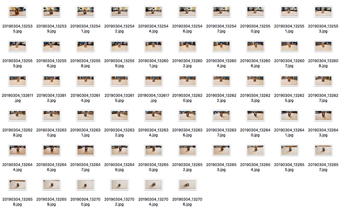
The program needs a lot of pictures to do a good job. I made a first attempt with 20 pictures and the program discarded a lot of them so it didn't work at all. I decided to put white paper underneath the object (see below) and take a lot of pictures (56) only slightly moving around it each time.
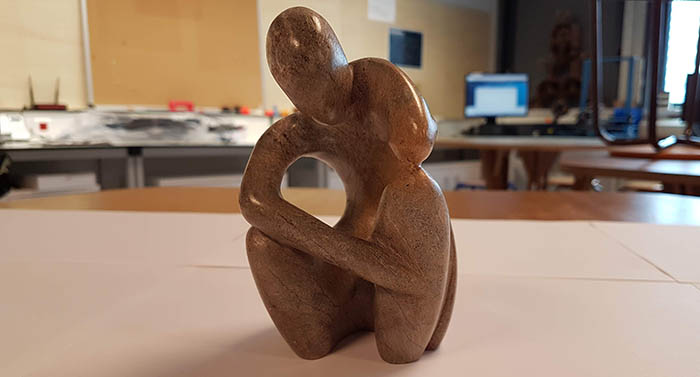
It is you that needs to rotate around the object to take pictures and not the contrary. The software uses clues from the environment to calculate angles and depths.
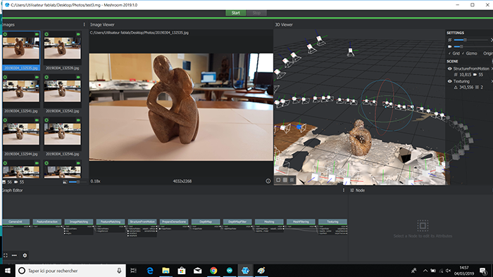
I just dragged and dropped the pictures on the interface of the program and clicked on start. The program then goes through a series of modules (which you can fine tune if you want) to process the pictures and recreate the object in 3D. We can see the software figures out where the pictures were taken around the object. It took approximately 2 hours.
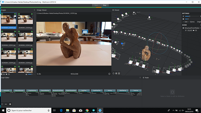
Here you can see the end result. I thought the white paper would help getting a cleaner result, but we can see that there is still a lot of background and unwanted mesh around. We'll have to clean that up!
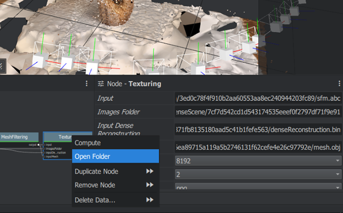
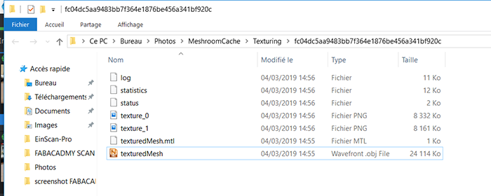
To export the 3D object and use it in another software, you need to right-click on the last module and choose "Open folder". This will open the folder with the output files. And what interests us here is the obj file!
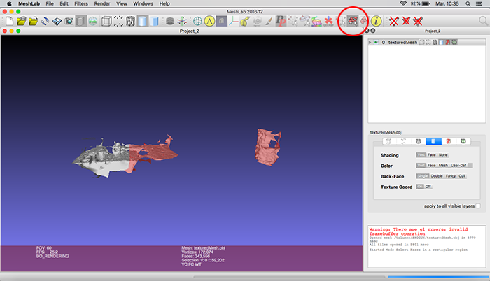
To clean up the mesh I used Meshlab, which is an opensource software to process and edit meshes. As you can see below, the output from Meshroom is pretty messy. The object I wanted is actually quite small compared to the global mesh!
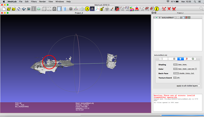
So I used the selection tool to select the unwanted faces and deleted them with the delete faces tool.
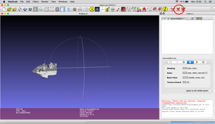
Then I applied a series of smoothing filters (Filters > Smoothing, Fairing and Deformation > Laplacian Smooth) and here is the final result! Ready to print!
Conclusion
Challenges
Using a 3D printer was more of a challenge than I thought. I ran into a lot of problems but I suppose that’s how we learn. I have a better idea of how to troubleshoot now. And I have to say I’m really happy with the results. The prints are quite durable, smooth and very detailed.
Achievements
Diving into Rhino and Grasshopper was hard but a lot of fun! I’m proud I understood the workflow and the algorithm used to generate this complex structure. I think I found my weapon of choice for my future modeling jobs!
I had a lot of doubts concerning 3D scanning but I'm very pleased with the end result! Meshroom is a very powerful software and I will have to dig a little deeper to have even better results.