Week 14: Networking
02/12/2019 - Stéphane Muller
Group assignment: send a message between two projects. Individual assignment: design, build and connect wired or wireless node(s) with network or bus addresses.
This week was a bit complicated for me because I had a job outside of the Fab Academy. I didn't have as much time as I would have wanted. I decided to make the most of it though and try my hands on bus communication. We will use that to communicate during machine week.
Planning and list of tasks
- Review Neil's bus code
- Coding the masters
- Coding the slave
- Testing
Step by step
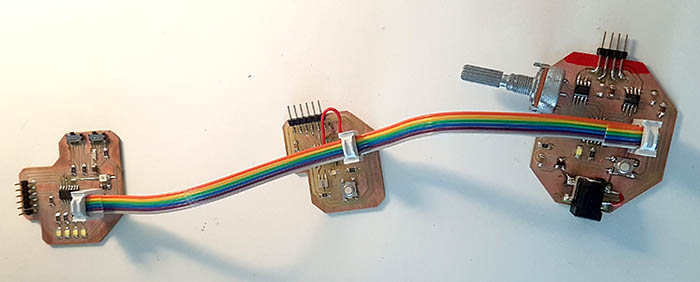
For this assignment I will be re-using 3 of my old boards and use two of the ISP pins for the communication. The idea here is to have two master boards and one slave (board on the far left). When I click on the button from one of the master boards I want the slave board to turn one of its four LEDs on or off, depending on which master the command is coming from. So to do this I will need to implement a source address as well as a destination address.
Coding the masters
Most of the code I used for the masters is recycled from my previous projects (to handle the button and the LEDs). Which is cool, because I could concentrate on the bus part of the logic, but which ultimately gave me some trouble as well...
The first new thing I did was define IDs for the nodes. node_cmd is just the node to be commanded, so the slave board.
#define node_id '2'
#define node_cmd '0'
Then I execute the code below when the button is pressed:
output(bus_direction, bus_pin_out);

put_char(&bus_port, bus_pin_out, node_cmd);
put_char(&bus_port, bus_pin_out, node_id);

input(bus_direction, bus_pin_out);

PORTB ^= (1 << LED);
_delay_ms(50);
PORTB ^= (1 << LED);
_delay_ms(50);
PORTB ^= (1 << LED);
_delay_ms(50);
PORTB ^= (1 << LED);
It's the same thing as serial communication with the computer really. I used the same method from Neil's code. First I put out the destination node (the board to be commanded) and then I send the source node to let the slave board who's giving the order.
The very first line of this snippet and the line after the serial communication are very important. Since all the boards are listening and communicating on the same line, only one board can be sending a signal at the same time. So when a board wants to send a signal, the pin connected to the bus needs to be in output mode (obviously), but as soon as it is done communicating it needs to go back into input mode.
And finally I make the own board's LED blink twice just to let the user know something has been sent.
I said I ran into trouble when re-using my code because coding in C like that is complicated when you're not using the same pins or the same variables. And also because the code is not very explicit, it's easy to forget one instruction. In this case I was ready to throw my motor board out the window because I thought it was broken, when actually I had just forgotten to enable the pull-up resistor on the button pin... Problem I didn't have on my echo board because I used a real resistor on that one.
Coding the slave
For the slave board I started out by coding the LED control function. A routine that would just light up the right number of LEDs.
void lightControl(void){                        // this function will control the LEDs
  if( led_strip == 0 )
  {
    PORTA = (0 << LED1);
    PORTB = (0 << LED2) | (0 << LED3) | (0 << LED4);
  }

  if( led_strip == 1 )
  {
    PORTA |= (1 << LED1);
    PORTB = (0 << LED2) | (0 << LED3) | (0 << LED4);
  }

  if( led_strip == 2 )
  {
    PORTA |= (1 << LED1);
    PORTB = (1 << LED2) | (0 << LED3) | (0 << LED4);
  }

  if( led_strip == 3 )
  {
    PORTA |= (1 << LED1);
    PORTB = (1 << LED2) | (1 << LED3) | (0 << LED4);
  }

  if( led_strip == 4 )
  {
    PORTA |= (1 << LED1);
    PORTB = (1 << LED2) | (1 << LED3) | (1 << LED4);
  }

  if( led_strip == 5 )
  {
    PORTA = (0 << LED1);
    PORTB = (1 << LED2) | (1 << LED3) | (1 << LED4);
  }

  if( led_strip == 6 )
  {
    PORTA = (0 << LED1);
    PORTB = (0 << LED2) | (1 << LED3) | (1 << LED4);
  }

  if( led_strip == 7 )
  {
    PORTA = (0 << LED1);
    PORTB = (0 << LED2) | (0 << LED3) | (1 << LED4);
  }
}
Nothing too complicated. I could have used a simple switch/case instruction too, but it does the same thing.
Then I needed to handle the message received and act accordingly and for that I put this code in the while loop:
while (1) {
 get_char(&bus_pins, bus_pin_out, &chr1);                        // get the destination node
 get_char(&bus_pins, bus_pin_out, &chr2);                        // get the source node

 node_dest = chr1;
 node_src = chr2;

 if (node_dest == node_id) {
    output(serial_direction, serial_pin_out);
    static const char message1[] PROGMEM = "Destination node: ";
    put_string(&serial_port, serial_pin_out, (PGM_P) message1);
    put_char(&serial_port, serial_pin_out, node_dest);
    put_char(&serial_port, serial_pin_out, 10); // new line

    static const char message2[] PROGMEM = "Source node: ";
    put_string(&serial_port, serial_pin_out, (PGM_P) message2);
    put_char(&serial_port, serial_pin_out, node_src);
    put_char(&serial_port, serial_pin_out, 10); // new line

    PORTB ^= (1 << LED4);
    _delay_ms(50);
    PORTB ^= (1 << LED4);
    _delay_ms(50);
    PORTB ^= (1 << LED4);
    _delay_ms(50);
    PORTB ^= (1 << LED4);

    if (node_src == '1') {
      led_strip++;

      if (led_strip == 4)
      { led_strip = 0; }
    }

    if (node_src == '2') {
      led_strip--;

      if (led_strip < 0)
      { led_strip = 3; }
    }

    lightControl();
    }
 }
It listens to the bus and reads the destination node first, then the source ID. Then I check if the board is in fact the destination node and if it is I do the rest.
I output a message to the computer with the destination and the source addresses, then I blink the fourth LED (for debugging purposes) and, finally, depending on the source node, I either add or subtract the LED counter.
Demo
Here's a quick demo of my 3 boards communicating to each other!
Conclusion
I really enjoyed this project and I wish I would have had more time to do something a little more challenging like I2C for example. I'm looking forward to using the ESP for my final project.
I'm starting to be more confident in my electronic and programming skills though. That feels good!