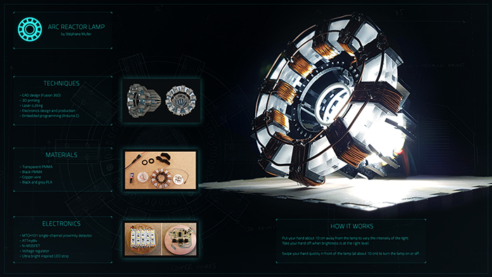
Final Project
01/22/2019 - Stéphane Muller
The objective of the final project is to demonstrate the skills developed during the previous weeks. The goal is to keep it as affordable as possible and to design and fabricate everything yourself instead of buying off-the-shelf components.
Final project presentation

Final project log book
01/22/2019: Check out the first week's assignment to read about my first ideas.
02/05/2019: During week 3 I did 3D models of my first two project ideas. It gave me a better idea of what they would both look like and some design issues I needed to be careful about. Like the size of my drawer and the space I needed to anticipate for the mechanism and the electronics. Or the distance between the thermostat and the wall. I think it'll need to be adjustable to be able to fit above a variety of heaters. Modeling the FabNest made me realize that the initial size I had in mind might be a little small for the electronics and the motor. I will have to work on the PCB first and model around it.
03/20/2019: After a lot of thinking, I decided on a new final project. The two first ideas I had didn't motivate me enough, so I switched to an old idea of mine: making a replica of Iron Man's first arc reactor. This replica would be a smart lamp. I wanted to use capacitive sensing to detect proximity and gestures, I also wanted to be able to access the lamp through WiFi. I really like this idea and with Avengers Endgame coming soon, this would be the perfect way to get in the mood.
04/08/2019: I have tested Neil's capacitive touch circuit and the step response program with a breadboard. I was able to detect touch but not proximity (more than a couple of mm away).
04/15/2019: Check out week 13 on applications and implications to read about my (final) new idea.
04/17/2019: Made my first drawings of the project. I'm starting to have a clearer idea of what it'll look like, how I'm going to make each piece and the functionalities of the object.
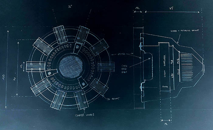
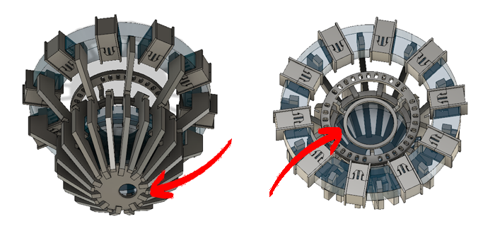
05/14/2019: I started modelling parts in Fusion 360.
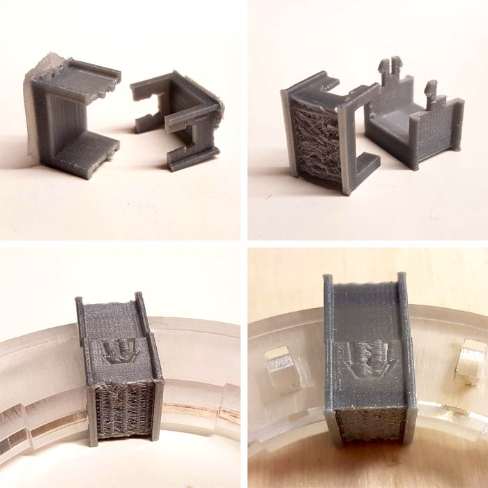
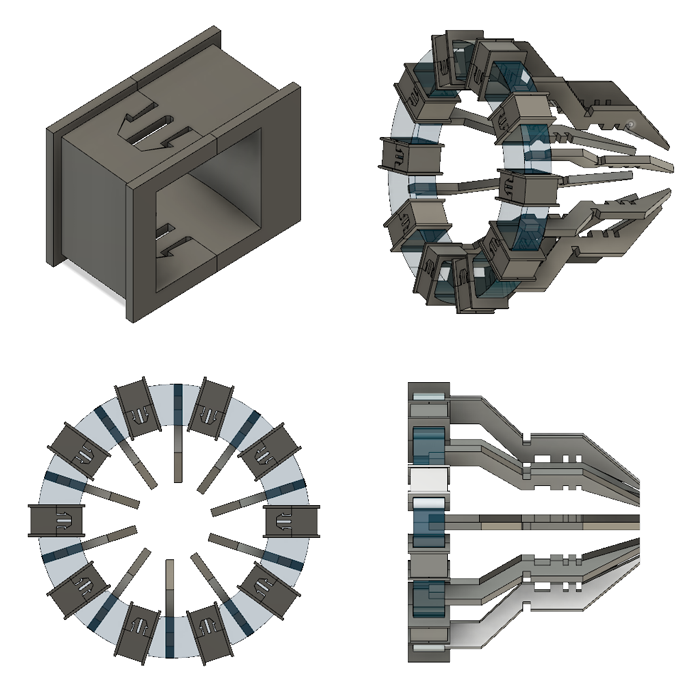
First I designed the arc in Illustrator and laser cut it twice in 6mm PMMA. Then I worked on the copper wire support. This part was quite tricky to model because it's quite small and I needed to make two parts to fix it on the arc. I designed a small clip with a male and female part.
I had to make 4 iterations before it worked perfectly. The first time I used a raft and supports when I printed it but the model is too small and it messed up the part. The dimensions were off too and it didn't fit perfectly on the arc. The second iteration I used no raft and no support but the result was a little crappy and the clips broke. My third try I used supports but only for the bottom part and it worked but it wasn't perfect so I made some tiny adjustments, added more tolerance. And the fourth worked like a charm.
I also made a lot of progress in modelling the whole lamp in Fusion. I have designed the back of the lamp and now know how I'll hold everything together.
05/27/2019: I started working on the electronics.
During my research of capacitive sensing and proximity sensing, I found a sensor (MTCH101-I/OT) that, in theory, would work exactly the way I want. So I designed a board to test this component.
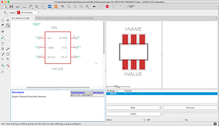
Unfortunately, I couldn't find the component in any library, so I had to create the package and the footprint on Eagle myself first. I followed 3 tutorials from Autodesk which worked great. First you need to create the package, then the symbol and finally you put everything together in a device. You can download the Eagle library I created here.
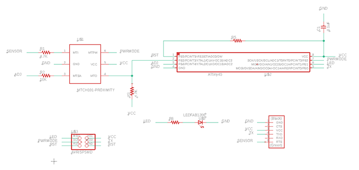
Once I had that covered, I could start designing the board. I used the recommended schematics described in the datasheet and added an LED, an ISP and a FTDI header. Since it's only a test board, I didn't need that many pins so I chose an ATTiny85.
You connect a conductive surface to the component and it sends a HIGH when something is at the right distance. You can adjust the distance by sending an analog value on the adjust pin.
I milled the board and soldered all the components but the proximity sensor because I'm still waiting on the order to arrive... Let's hope it'll get here soon.
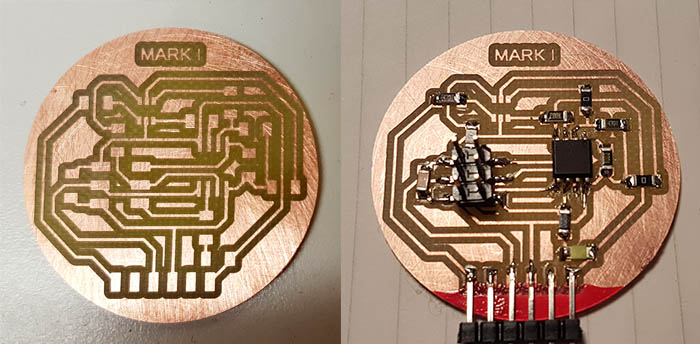
It was also the first time I needed to make a board of a certain size. And I discovered that mods doesn't take into account the radius of the endmill when milling the outline... Granted it's only 0.7mm, but still...
I uploaded some test code to check if my board was working (it was) and now I wait.
05/28/2019: More on electronics.
Even though I don't have the component yet, I wanted to start coding so I took a closer look at the datasheet to know if I should set pins HIGH or LOW and what effect it would produce. In doing that I realized that I would have a problem with my current board... I wasn't going to be able to adjust the sensitivity with a PWM output without a low-pass filter in between. The datasheet makes a reference to an application note so I checked it out and used it for my calculations. It was time to dust off my telecommunication degree.
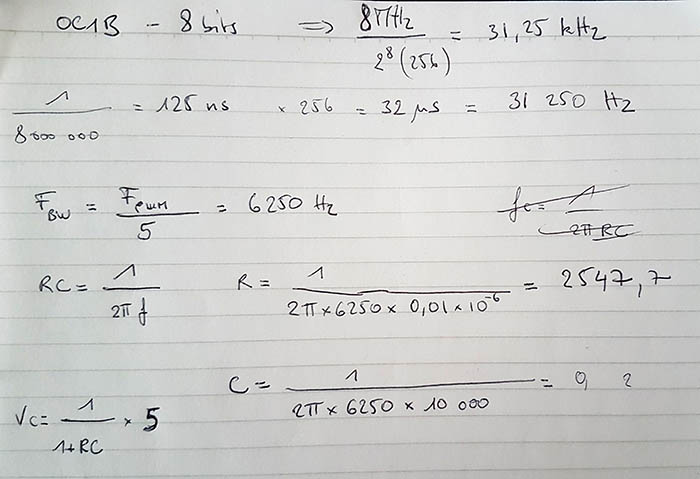
According to the note, PWM generates unwanted harmonics of the base frequency at which the modulation is made. So before calculating a cut-off frequency, I had to find out at what frequency the PWM was generated with my ATTiny.
My ATTiny runs at 8MHz (clock is not divided) and the pin I'm using uses timer1 which is an 8bit timer (boy was I glad I digged deeper during embedded programming week here). That means that the timer is incremented every clock beat, so every 125ns. Hence, the timer overflows every 32µs. Which gives us a frequency of 31.25kHz.
Now, the noise peak we want to cut off is at that precise frequency and since there is only a -3dB attenuation at the cut-off frequency, we need to cut-off before that. In the note they divided the frequency by 5, so I'll try that. That gives us a cut-off frequency of 6.25kHz.
Using the low-pass RC filter equation and choosing a 0.01µF capacitor, we get a 2.5KΩ resistor.
I wanted to see if I could salvage my first circuit and just use a flywire capacitor so I did the calculations with a 10K resistor, and it gave me a 2.4nF capacitor. I'll have to check but I'm not sure we have those at the lab.
The other part of my circuit on which I can start working already, is the LED board. I'm simply going to put as many LEDs as I can on the surface that I have. The best way to wire multiple LEDs is in parallel and with a resistor each. With a voltage drop of 3.5V at each LED, in series won't work (not with 5V at least and with 12V you can only put 3). Using only one resistor could work but it's a very bad option since all LEDs are not EXACTLY the same.
05/31/2019: More on electronics.
I received my proximity sensor today! You can see the beast soldered on the picture below. I also added a 2.2nF capacitor to make the low-pass filter I needed.
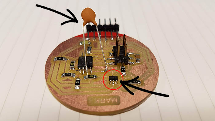
I was finally able to test the component and it seems to be working pretty well! I used some copper wire as a sensor and, at maximum sensitivity, was able to detect my hand at about 10cm. In the datasheet it says I should be able to detect up to 30cm provided I have a bigger surface. I'll do some further tests.
I also tried adjusting the sensitivity with PWM, to check if my low-pass filter was working and it does! Here is the piece of code I used to do my tests.
// SoftwareSerial library without the TX,
// because I didn't have enough pins and didn't need it
#include <SendOnlySoftwareSerial.h>

// Define all the pins used
#define LED 1
#define PROX 3
#define ADJ 4
#define PWRMODE 2
#define TX 0

SendOnlySoftwareSerial mySerial(TX);

void setup() {
  pinMode(LED, OUTPUT);
  pinMode(PROX, INPUT);
  pinMode(ADJ, OUTPUT);
  pinMode(PWRMODE, OUTPUT);

// Proximity sensor parameters
// 0 ADJ is the highest sensitivity, 255 is the lowest sensitivity
// HIGH PWRMODE means normal mode, LOW means sleep mode
  digitalWrite(PWRMODE, HIGH);
  analogWrite(ADJ, 0);

  mySerial.begin(9600);
}

void loop() {
  if (digitalRead(PROX) == LOW){
    digitalWrite(LED, HIGH);
  } else {
    digitalWrite(LED, LOW);
  }

  delay(1);
}
The proximity sensor only sets one of its pins LOW when it detects something at the adjusted sensitivity. The challenge now is to code a brightness variation depending on the proximity.
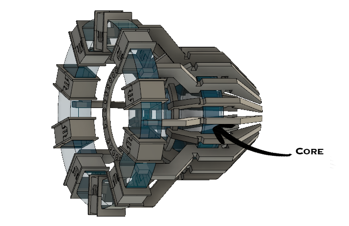
Today I also continued adding details to the lamp in Fusion. I added some structure and made a bigger core to add LEDs. There is still a center (decorative) piece that I can't figure out where to fix yet.
06/03/2019: Embedded programming and design.
Since my proximity sensor is working, I can now focus on coding. I tried varying the sensitivity very quickly with a for loop to detect a precise position but the readings I get are a little messed up. I think capacitive sensing is much too sensitive to noise for such an application. So I had another idea.
I thought, why not vary the brightness while my hand is close and keep the brigthness level where it is when I take my hand off. That's for a smooth variation. Now, how about switching the light on or off with a single swipe in front of the lamp! And voilà!
Here is the code controlling the LED:
#include <SendOnlySoftwareSerial.h>

// define all the pins used
#define LED 1
#define PROX 3
#define ADJ 4
#define PWRMODE 2
#define TX 0

// define global variables
volatile int brightness = 0;
volatile boolean dir = true;
volatile int counter = 0;

// for debugging purposes
SendOnlySoftwareSerial mySerial(TX);

// function to reset the proximity detector
void resetProx() {
  digitalWrite(PWRMODE, LOW);
  delay(5);
  digitalWrite(PWRMODE, HIGH);
}

void setup() {
  pinMode(LED, OUTPUT);
  pinMode(PROX, INPUT);
  pinMode(ADJ, OUTPUT);
  pinMode(PWRMODE, OUTPUT);

// Proximity sensor parameters
// LOW ADJ means higher sensitivity, HIGH means lowest sensitivity
// HIGH PWRMODE means normal mode, LOW means sleep mode
  digitalWrite(PWRMODE, HIGH);
  digitalWrite(ADJ, LOW);

  mySerial.begin(9600);

// allow 1 second before sensing
  delay(1000);
}

void loop() {
// if something is detected
  if (digitalRead(PROX) == LOW){
    counter++;

// increase or decrease brightness by 1
    if (dir == true) { brightness++; }
    if (dir == false) { brightness--; }
    analogWrite(LED, brightness);

// delay 8ms otherwise it's too fast
    delay(8);
  } else {
// this part detects a quick swipe to turn the lamp on or off completely
// if the sensor detected something for less than 400ms then it was just a swipe
    if (counter > 0 && counter < 50) {
      if (brightness > 50) { brightness = 0; }
      else { brightness = 250; }
      analogWrite(LED, brightness);
    }
    counter = 0;
  }

// define the direction of the brightness change
  if (brightness > 254) { dir = false; delay(500); }
  if (brightness < 1) { dir = true; delay(500); }
}
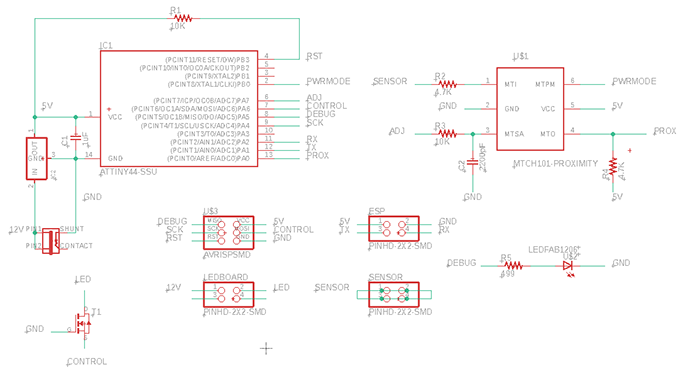
My proof of concept is now valid, I have a working board and a working code, let's start working on the final circuit design. I need to think about power and LEDs. I'll be using bright LED strips that require 12V, so I'll need a power jack, a voltage regulator, a transistor to control the 12V and pins for the sensors.
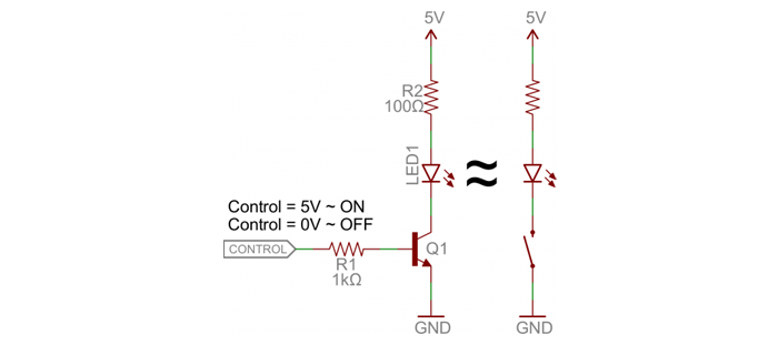
To control 12V with a 5V ATTiny, I'll be using an NPN transistor. To learn how to do that, I found a really good tutorial on Sparkfun. Here is the set up I'll be using (from that same page):
The new circuit design:
I also worked on my 3D model, on the piece in the center mostly and the back. In the back I put a cover and a hole for the cables.
06/04/2019: Laser cutting, milling and 3D printing.
I exported my sketches from Fusion in DXF to laser cut them (right click on the sketch's name and "Export to DXF"). But once I opened it in Inkscape the dimensions were off, each line was separate and I couldn't apply a different stroke color... So I imported everything in Illustrator to prepare the file.
I started out by laser cutting 2 "branches" to test them on my prototype and it fit perfectly! It's a very tight fit though, it's nearly impossible to get out. I'll have to be very careful during assembly. I laser cut the rest.
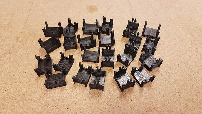
I launched the printing of my 10 copper wire supports (11 hours) and the center piece (2 hours). And here are the results, it's starting to look good! I'm excited now.
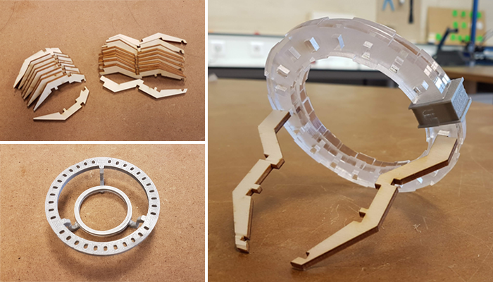
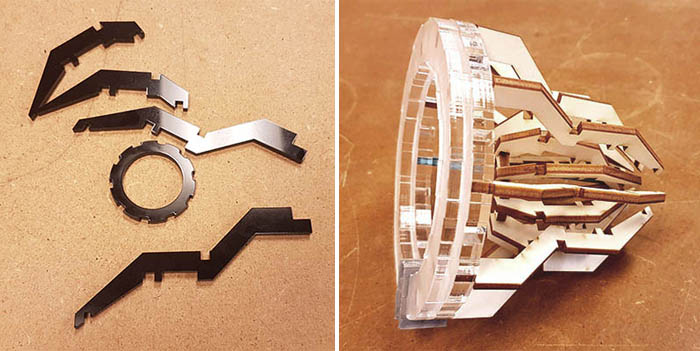
I discovered black PMMA and decided I will laser cut my pieces in them instead of wood (which I would have had to paint). It looks so good! And I assembled the wooden parts I cut on my prototype to see how it looked. I like it!
I have been doing a lot of things in no particular order until now, but now that everything is starting to be clear in my head I feel the need to make a list of what's left to do and in which order I need to do them in. So here is my list of things I still need to do:
- Adjust size and tolerances of some parts
- Laser cut all parts in PMMA
- Sand PMMA to make a diffusing white color
- Re-print defective pieces
- Clean up prints
- Finish final PCB design
- Route final PCB
- Mill PCB
- Solder components
- Upload code on board and test it
- Paste LED strips and solder them
- Install copper support
- Coil the copper on the arc
- Assemble all the central pieces together (branches, PCB...)
- Mount everything on the arc
- Finish design of the base
- Laser cut the base
- Assemble the lamp on the base
06/05/2019: Cut cut cut and mill mill mill.
I made nice progress today. All the pieces are now laser cut and 3D printed! I only need to sand the transparent PMMA to have it diffuse light.
Laser cutting PMMA and make it fit perfectly (down to 0.1mm) was quite a pain. I first made tests in black 3mm PMMA and noticed later that I had a different result on transparent 6mm PMMA... Then I had differences between the file on Illustrator and on Inkscape... I solved the problem by saving my Illustrator file as a PDF and importing it in Inkscape.
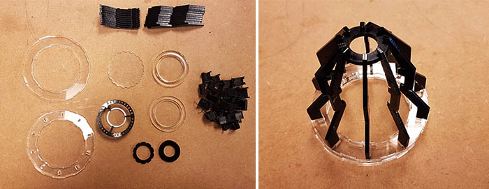
I also routed my board, milled the PCB and soldered all the components! Tomorrow I'll add the LEDs on the back and in the core.
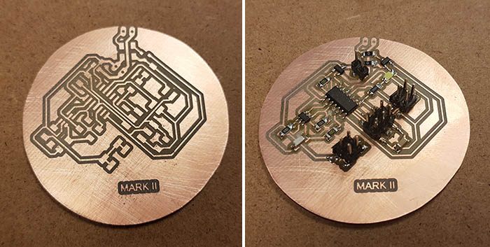
06/06/2019: Testing the board
Since today we had our last lesson from Neil, I didn't have much time to make some progress. I did however test my final board. The results were not as good as with my test board unfortunately. It seemed like there were a lot of noise in the readings. It was really odd since I was using almost the same board...
When comparing my first board with this one, the only thing that could make sense is that the noise came from the capacitor under which the sensor reading was passing. This capacitor was part of my low-pass filter. I didn't really need it anymore since I was going to use the HIGH or LOW setting, but I would have liked to be able to make some modifications in the code later on. I decided to remove the capacitor in the meantime.
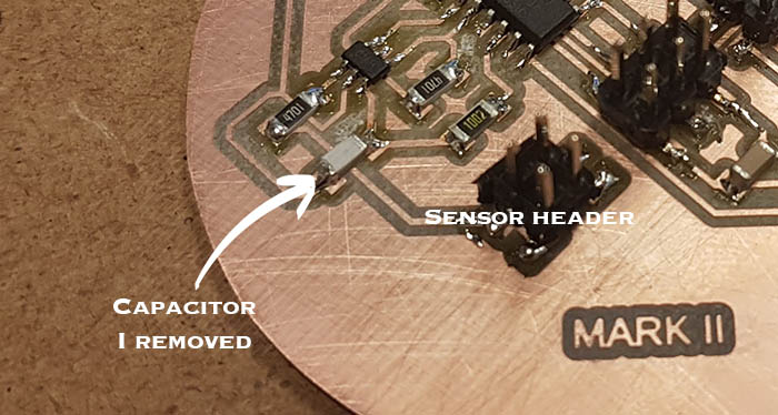
After tweaking the code a bit, it worked properly again.
06/07/2019: Assembling and testing
I started the day by cleaning the 3D printed copper supports.
Then I sanded the transparent PMMA parts to have a diffusing surface. I also made a first test with the copper supports and it looks really good already!
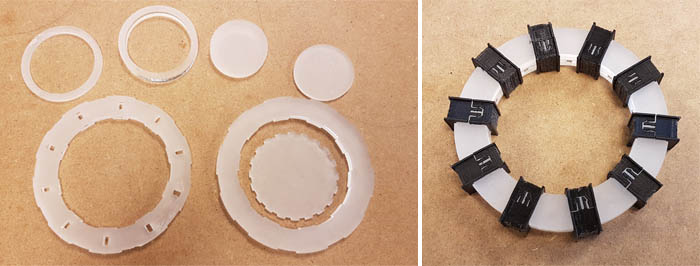
First copper wire winded and final result. It was tedious but it was worth it! It looks awesome. Everything holds well together. The copper supports are important, they're as much decorative as they are useful because they're the sensors.
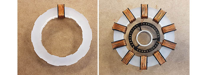
I also glued the core with super glue and put some LEDs on it. Super glue is really quick... I messed up twice, it wasn't well centered and I had to laser cut and sand the pieces again...
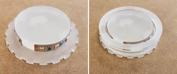
Soldering the copper windings together. I'm kinda stuck because I only managed to do one. The solder won't stick very well to the surface. I sanded off the insulation with a dremel everywhere I needed contact, but it's not enough. And the small copper wires are a nightmare to hold. I haven't figured out what to do yet.
But I tested the connection with a multimeter and it works. I connected my board to it to test the LED strip part of my board. It doesn't work... I inverted the pins of the transistor. I'll have to resolder them.
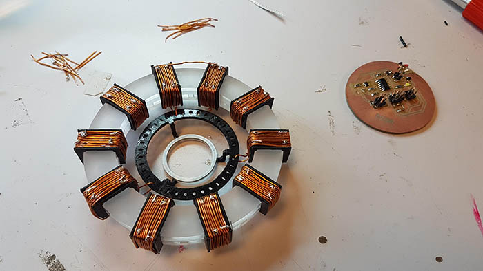
I have my head full, it's 8pm, I'm going on weekend. It'll have to wait Tuesday (Monday is a holiday). Everything is ready for when I get back.
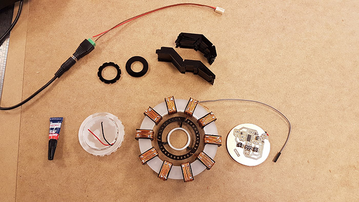
What I need to do when I get back on Tuesday. It's going to be tight... I still have Wednesday too, but I need it to work on my documentation, my slide and my video. And Thursday I start work as a fablab manager.
- Invert the transistor pins
- Solder the LED strip
- Solder the copper windings together
- Assemble all the central pieces together (branches, PCB...)
- Mount everything on the arc
- Finish design of the base
- Laser cut the base
- Assemble the lamp on the base
06/11/2019: Finish it.
A lot needed to be done today. I started by desoldering the transistor and resoldering it in a new position. Fortunately, I had connected the unused copper to the ground, so I could just shift the transistor to the right, with the right pin on the copper.
I also used copper tape to wire the LED strips. I just used a cutter to make the routes.
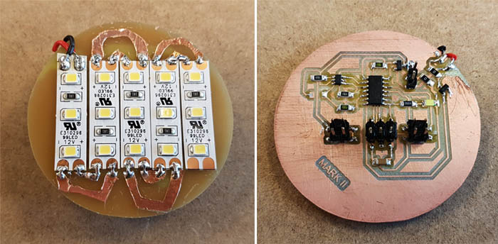
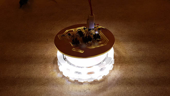
Then it was time for the first try! And it failed miserably... because in my code I forgot to trigger the LEDs! I just controlled the debugging LED I had soldered on my PCB. After that it worked fine.
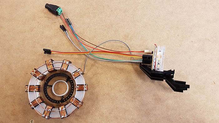
Soldering the copper windings together was a nightmare. My little copper strips were too tricky to solder and since there was still a lot of insulation on the copper wires, the solder wasn't sticking enough. Julie suggested I use copper rings and thin copper to keep them in place and then soldering them. So that's what I did and I'm pretty satisfied with the result.
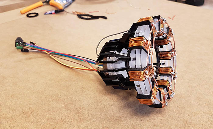
Then it was finally time to assemble everything... I used some super glue to fix the branches and it worked perfectly.
The final result is really cool. I love it! It looks like the real thing. It's a little rugged but the real copper and the black PMMA really makes this.
And a live demo to see how it looks... it's so badass, I love it!!!!
06/12/2019: The base.
Last thing I needed to do was laser cut the base. I generated a simple closed box on boxes.py and added some holes for the cables and logos for customization.
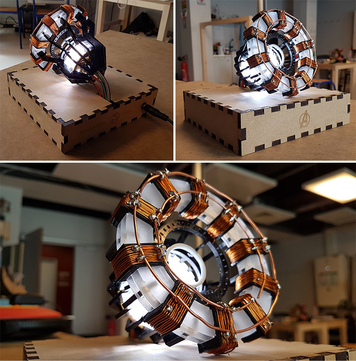
And here is the FINAL product!! Now it's time to make a cool video presenting this baby.
Bill of materials
| Name | Description | Price |
|---|---|---|
| PLA filament for the prints | It's a very small part of the lamp | 2€ |
| 11 meters of copper wire | 75cm per winding + enough to make the inner rings | 6.86€ |
| 5mm MDF wood | 600x300mm | 2€ |
| 3mm black PMMA | 600x300mm | 13.37€ |
| 3mm transparent PMMA | 600x300mm | 13.37€ |
| 6mm transparent PMMA | 600x300mm | 16.90€ |
| ATTiny84 | 0.69€ | |
| MTCH101-I/OT | Proximity sensor | 0.33€ |
| N-Mosfet transistor | To control the 12V for the LED strip | 0.75€ |
| Voltage regulator | To output 5V for the MCU | 0.75€ |
| LED strip | Ultra bright Inspired LED strip | 22.46€ |
| 79.48€ | ||