Week 3: Computer-Aided Design
02/04/2019 - Stéphane Muller
Model (raster, vector, 2D, 3D, render, animate, simulate, ...) a possible final project with as many different software as possible, and post it online. Check out the lecture.
I already have some experience with a couple of CAD software, namely Adobe Illustrator (vector), Adobe Photoshop (raster) and Blender (3D), so this week I’m going to focus on tinkering with ones I don’t know yet. During Neil’s lecture I was intrigued by the following: FreeCAD, Antimony and Fusion 360.
Research
Wikipedia tells me that FreeCAD is a free and open-source general-purpose parametric 3D modeler. It's aimed directly at mechanical engineering product design but also expands to a wider range of uses around engineering, such as architecture or electrical engineering. FreeCAD can be used interactively, or its functionality can be accessed and extended using the Python programming language and is currently in a beta stage of development.
Antimony is a CAD tool that uses a graph and nodes for modeling. I found the workflow very interesting and am very curious to test it. It feels more intuitive and easier to use than OpenSCAD, where you need to write code to model shapes.
I already had a go at Fusion 360 not too long ago and I enjoyed it very much. Fusion is a professional 3D CAD tool and works well with other tools from Autodesk, like Eagle for example. Its main focus is on mechanical design, like FreeCAD.
Adobe Illustrator is a professionnal vector graphics editor. Vector graphics are mathematically generated shapes, which means they don't pixelate when you scale them up. I already have some knowledge of this software but haven't used it in a while. This week is a great opportunity to freshen up my skills.
Planning and list of tasks
- Model my FabNest project in FreeCAD
- Model a parametric gear in Antimony
- Model my smart furniture project in Fusion 360
- Re-model my avatar in Illustrator
Step by step
3D modeling in FreeCAD
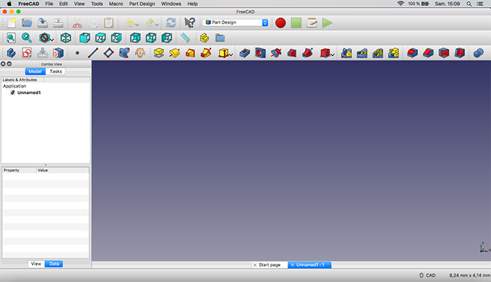
The first time I loaded FreeCAD I could not figure out how to use it at all. The scene was empty, there wasn’t even a grid or the xyz axis, and the buttons I clicked didn’t do much. So I decided to go look for some video tutorials on YouTube. I found a great series of videos (in French) that explained the basics and then it was like I saw the light.
So the first thing I had to do was go into part design mode and start sketching 2D profiles. I thought I was all set up but I seemed to be unable to move around in the scene. I was supposed to be able to rotate around using the scroll button and move left and right with the right click but nothing worked....
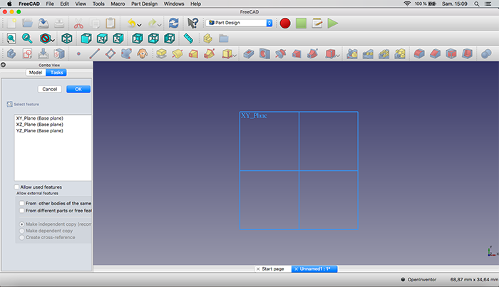
It turns out I wasn’t using the right 3D navigation mode... Be sure to check out the documentation to get the different combinations you can have. I decided to switch to blender mode.
In FreeCAD my goal was to make a first model the casing of my FabNest project. I started out by creating a parametric profile, with as many constraints as possible, and then making a revolution.
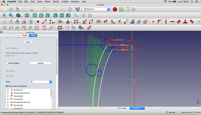
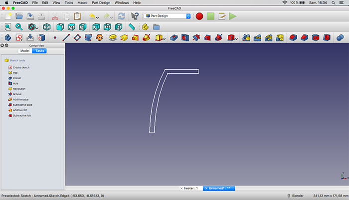
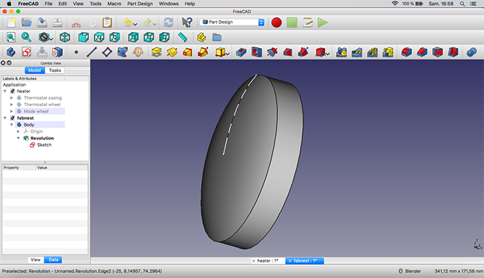
At first I had a hard time with the b-splines because they didn’t work exactly the same way as I was used to in Illustrator. It’s complicated to juggle with all the constraints when you draw your own shape. You need to be careful and make sure that the shape is closed, otherwise the revolution won’t work. It can be as painful as 2 points being very close to each other but not constrained together… But eventually I prevailed.
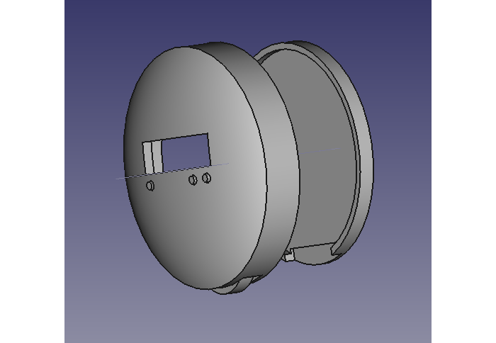
I then went into part mode to do a bunch of of boolean operations. I needed to make a void for the LCD display and for the buttons. For the buttons I started with one cylinder for the hole, duplicated it a number of times and moved each copy using the properties panel. Then I duplicated each cylinder again and made the radius smaller for the actual buttons. And finally I did a boolean difference for the holes.
There’s a small but annoying display bug I found. When you double click on an object to edit it, everything disappears the first time. You need to get out of editing mode and double click a second time for everything to appear correctly again.
And here’s the end result! It looks very simple but it took me quite a while to get there! I learned a lot and I think I got the hang of it.
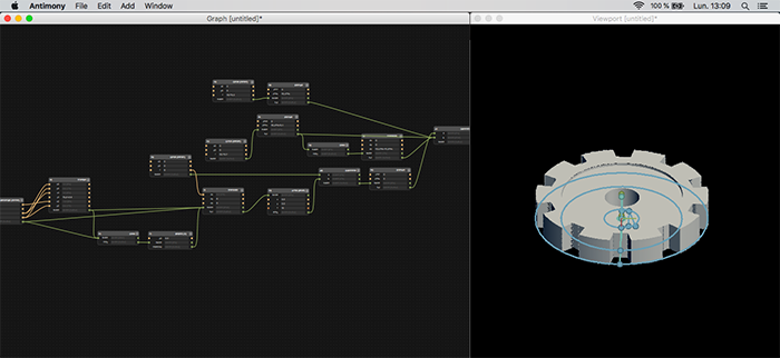
3D modeling in Antimony
For Antimony I went straight to some video tutorials. It seemed too obscure to try to figure out on my own. And the 2 videos I watched were enlightening! The first showed how to make a parametric 2D profile and the second was a quick overview from the creator of the software. Both gave me a very good sense of what the tool could do and its underlying principles.
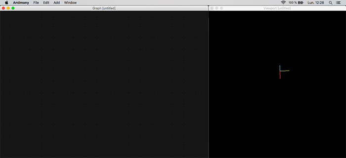
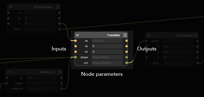
Antimony’s interface is very minimalistic but once you’ve understood the philosophy of the tool and how the graph works, it’s actually pretty straight forward. I for one find it very logical and intuitive. You create nodes in the graph, each node being an operation, and you link them together. Input on the left, output on the right, parameters in the middle.
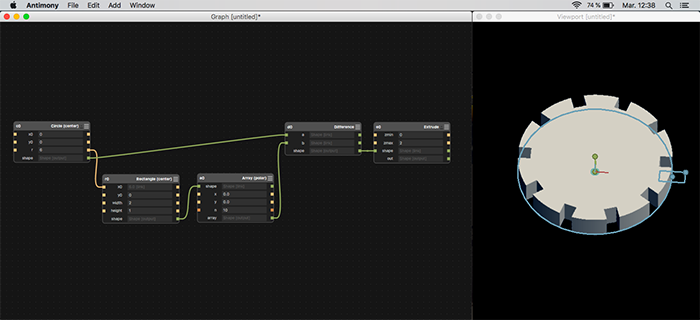
In this tool I wanted to design a fully parametric gear. Sounds easy but it really is not. First thing I did real quick was to create a circle, then a rectangle. Duplicate the rectangle using a polar array, make a boolean difference on the circle and then extrude the result.
It looks kinda like a gear but it’s not really. And it wasn’t in the least bit parametric. I needed to make the top of the rectangle wider and add a lot of constraints.
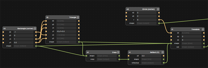
So I started over. I couldn’t make just a random 4 edged shape so I decided to add a triangle next to the rectangle. First I tried putting the rectangle and the triangle on the edge of the circle but the constraints were to complicated to manage. So I decided to leave the shapes at the origin and use the translate operation instead.
The most efficient solution I found was to make a half of the dent profile (rectangle + triangle), copy it, reflect it on the y axis and then translate the whole thing using the radius of the circle as the translation distance.
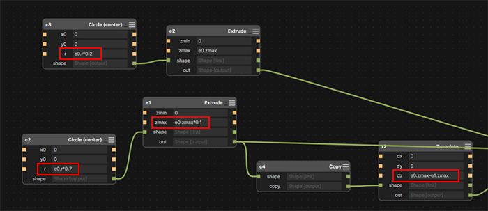
Then I wanted to create a small grove in the gear (on both sides) and a hole for a shaft. That was another challenge because I wanted to make that grove parametric (a percentage of the gear radius). And at first I couldn’t figure out how to do it in the graph. After a little bit of research I found another page on the creator’s website which explained how to reference other variables and write formulas in the parameter fields.
To reference a parameter from another node, just type node_name.parameter_name. Then you can use regular math operators to work with them.
And then everything clicked… I felt like I had fully understood the tool and all the basic operations. Here you can see the final result.
Although the essence of the tool is simple, I still struggled with it and how the different operations interacted with each other. The hardest part is being able to decompose, or deconstruct in your head, the shape you want to do and model it. To find the right (and the simplest) sequence of operations. That was (very) hard.
The final result:
3D modeling in Fusion 360
As I said, I already had a little experience with Fusion 360 so I was already familiar with the user interface. It’s quite similar to FreeCAD actually but more polished and with less bugs.
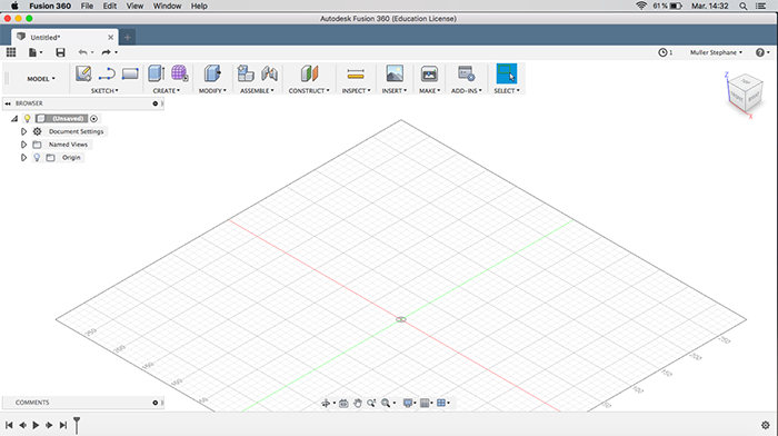
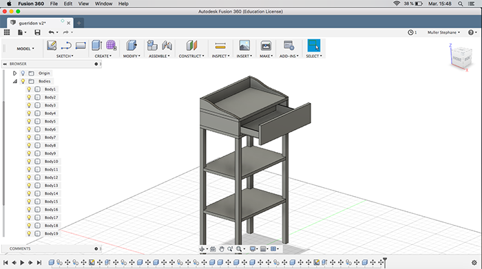
So here my goal is to make a first 3D model of my smart furniture. My initial design is rather simple and consists mainly of boxes, so I created a lot of boxes and used the move/copy tool a lot.
I did however use the sketch mode to draw the profile of the middle planks and then extruded it.
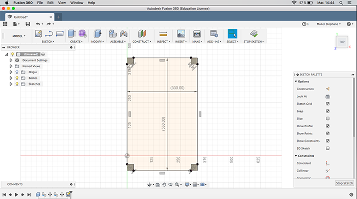
I didn’t have a lot of time left so I must confess my model is not parametric at all. However, I discovered a very useful dialog box to do just that. Here you can set the settings for all your objects and give them name to make it clearer (like in the example below).
Here is the end result:
Vector design in Illustrator
To refresh my skills in vector graphics I will redraw my avatar: Mugen, a character from the anime Samurai Champloo. My intention is to use it with the vinyl cutter and the hot press next week and make a T-shirt with it.
So I started out by simply copying and pasting a jpeg picture I found on Google Images.
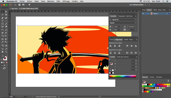
Then, with the pen tool I started detouring the silouhette. Since there aren't a lot of colors, the idea is to have the black silouhette and then add the colors, layer after layer. The difficulty here is to stay as close as possible to the outline with the beziers curves. It takes a little practice but you get the hang of it.
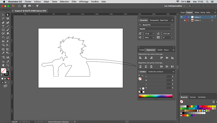
I used the pathfinder tool a lot here. This tool enables you to do boolean operations. So in the example below I made a difference operation to carve out the sword handle.
And the final result, showing all the layers:
Conclusion
Challenges
The hardest part of CAD in my opinion is to be able to decompose - or deconstruct - the object you want to model, in order to recreate it. It's to find the right sequence of operations (extrusion, revolution, boolean operation...) to achieve your goal. It's a very interesting and challenging exercise. It forces you to really think about how things are made.
Achievements
I'm very satisfied with what I have achieved this week! I have gained sufficient knowledge in all 4 tools I have chosen to be able to create reasonably complex objects. I'm confident I'll be able to do more in the coming weeks, depending on my needs. I also have a better idea and understanding of what these tools can do and which one is better for which job.