
Week 9: Embedded Programming
Assignment
☑ Read a Microcontroller Datasheet
☑ Group: compare the performance and development workflows for other architectures
☑ Program your board to do something
☑ EXTRA: Make a Fabkit/Shashakit/Fabio
BRAINSTORMING
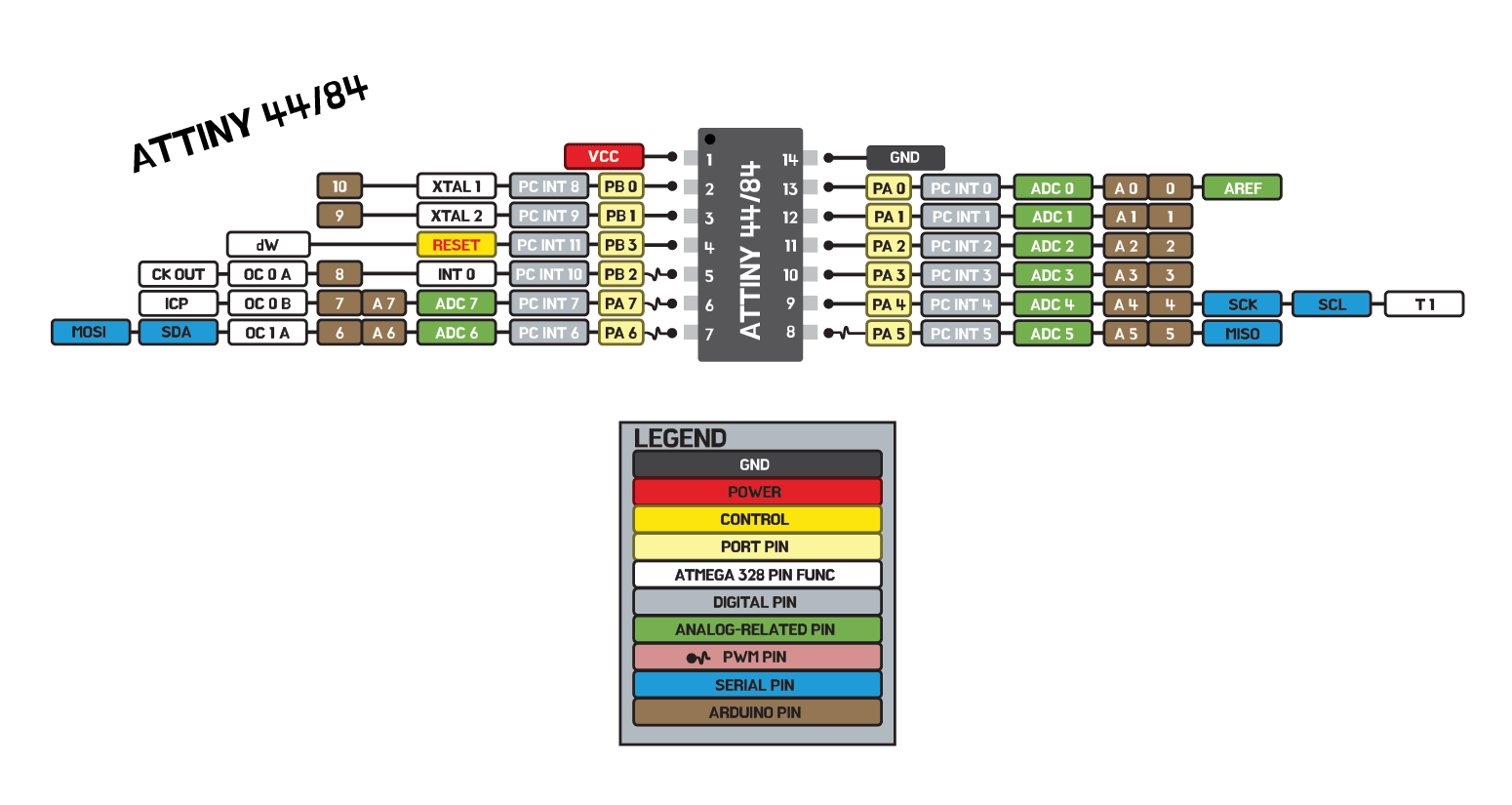
Read a Microcontroller Datasheet
1.1.1 VCC
Supply voltage.
1.1.2 GND
Ground.
1.1.3 Port B (PB3:PB0)
Port B is a 4-bit bi-directional I/O port with internal pull-up resistors (selected for each bit). The Port B output buffers have symmetrical drive characteristics with both high sink and source capability except PB3 which has the RESET capability. To use pin PB3 as an I/O pin, instead of RESET pin, program (‘0’) RSTDISBL fuse. As inputs, Port B pins that are externally pulled low will source current if the pull-up resistors are activated. The Port B pins are tri-stated when a reset condition becomes active, even if the clock is not running.
I organized the pin out datasheet to be able to find things quicker.
so far, all I know is that the brown ones and the blue ones are important to me right now.
because I will need to look at them when I am coding with Arduino.
[What I learned this week from class]
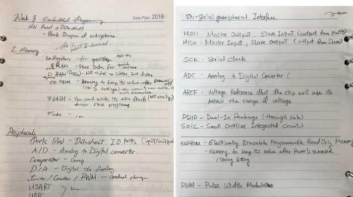
There are butt ton of information that I had to learn this week without actually making sense of them all.
(I am hoping that in the future I will be able to understand some of it)
SPI (Serial Peripheral Interface)

    MOSI - Master Output, Slave Input (Output from Master)
    MISO - Master Input, Slave Output (Output from Slave)

    SCK - Serial Clock: How it keeps time (How accuarate?)

    ADC - Analog to Digital converter

    AREF - Voltage reference that the chip will use to know the range of Voltage.

    PDIP - Dual-In Package (Though hole)
    SOIC - Small Outline Integrated Circuit.(SMD - Surface Mount)

    EEPROM - Electrically Erasable Programmable Read Only Memory.
            Memory to keep its value after the power is removed
            (stores setting)

    PWM - Pulse Width Modulation : a method of reducing the average power from electric signal
            by chopping them up. It turns switch between supply and load on and off at extremely fast speed.

Peripherals (Hardware Input/Output Device)

    Ports (pins) - Datasheet IO (input/output) parts.

    A/D - Analog to Digital

                ..... and then I got lost...
        But knowing these vocab will be helpful when I read datasheets
        (at least I will be able to recognize them)
Compare other architectures
I did not have a group to look through other architectures together, so I looked through other classmates to get some more information. I was able to get a lot of help from my friends Pamela, Flavie in Oshanghai, and Rico in Kamakura! Pamela's Documentation
Rico's Documentation
Flavie's Documentation
Program your board to do something
I had programmed my board to do stuff couple weeks ago.
 I moved on from there, and worked on using the button to control which I didn't get to do last time.
I tried using [#define] for naming your pins, and [if] & [else] code.
#define BUTTON 3 //I tried using "define" The button is connected to Attiny44 in pin 3
int val = 0;
void setup() {
// put your setup code here, to run once:
pinMode(6, OUTPUT); //My three LEDs are outputs in pins 6,7,8
pinMode(7, OUTPUT);
pinMode(8, OUTPUT);
pinMode (BUTTON, INPUT); //I have defined my button as BUTTON already so I just need to write the name.
}
void loop() {
// put your main code here, to run repeatedly:
val = digitalRead(BUTTON);
if (val == LOW) {
digitalWrite(6, HIGH);
digitalWrite(7, LOW);
digitalWrite(8, LOW);
delay(500);
digitalWrite(6, LOW);
digitalWrite(7, HIGH);
digitalWrite(8, LOW);
delay(500);
digitalWrite(6, LOW);
digitalWrite(7, LOW);
digitalWrite(8, HIGH);
delay(500);
}
else {
digitalWrite(6, LOW);
digitalWrite(7, LOW);
digitalWrite(8, HIGH);
delay(500);
digitalWrite(6, LOW);
digitalWrite(7, HIGH);
digitalWrite(8, LOW);
delay(500);
digitalWrite(6, HIGH);
digitalWrite(7, LOW);
digitalWrite(8, LOW);
delay(500);
}
}
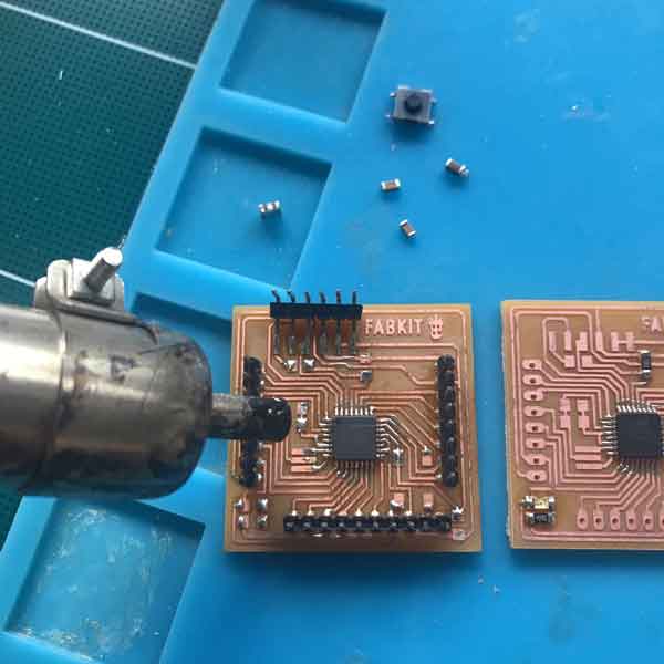
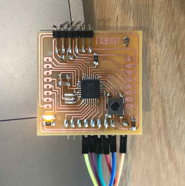
Extra: Make a Fabkit/Shashakit/Fabio
I decided to make a Fabkit because it looked most compact and square.
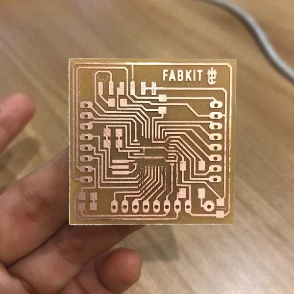
 I had to clean up on Eagle because the traces are pretty thin so I had to make adjustments
in some arears around the pins for ATMega so that I wouldn't have to do a lot of manual cutting. I had soldered on everything before understanding what each pins were...
so I was bound to have problems. (READ important datasheets and schematics!!!)
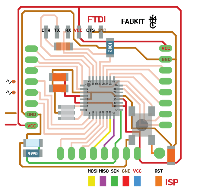
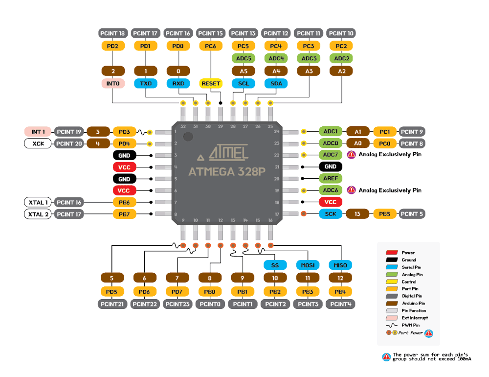 I re-made the colorful pinout and schematics so that it was easier for me to use.
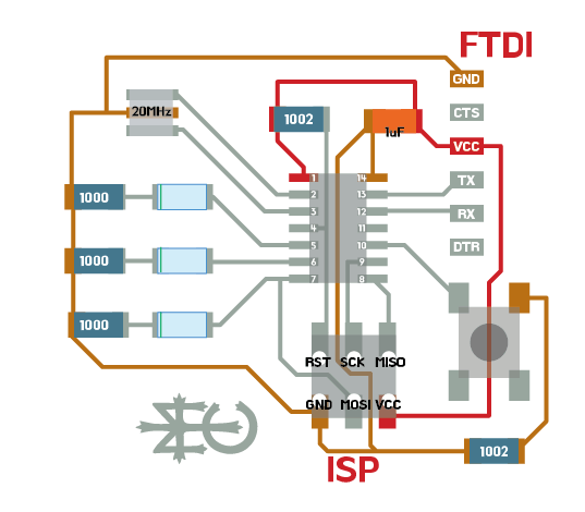
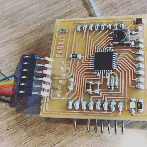
 My problem was with the FTDI connector. the pins were blocked when I put in the FTDI.
(NOW I know that all I needed was to change the connecting pins of the FTDI, but I was pretty close to burning it.)
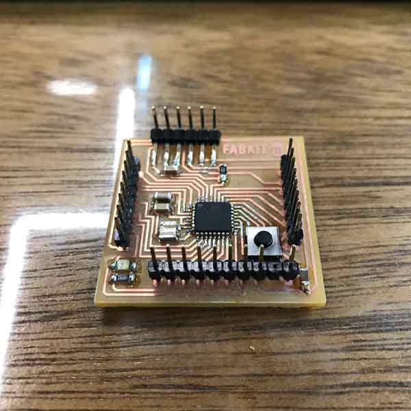
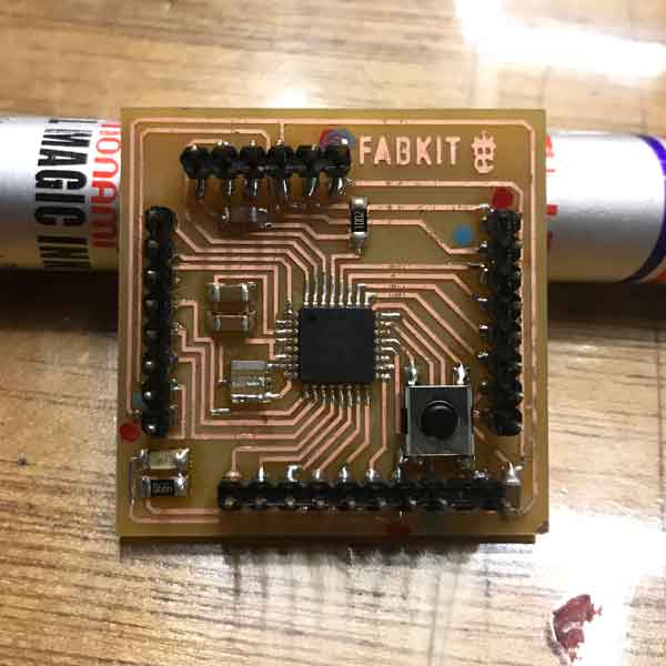
 In the end I had to make a new one.
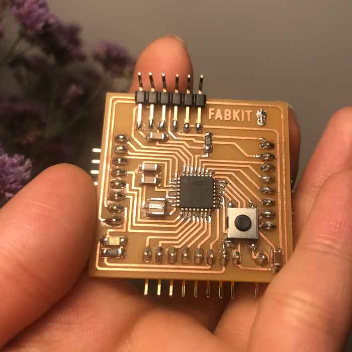 It's not bad.
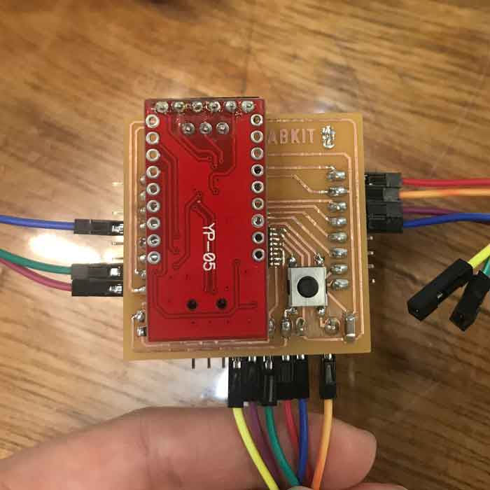
Programming
Connect your newly made Fabkit to your microcontroller and to your computer.
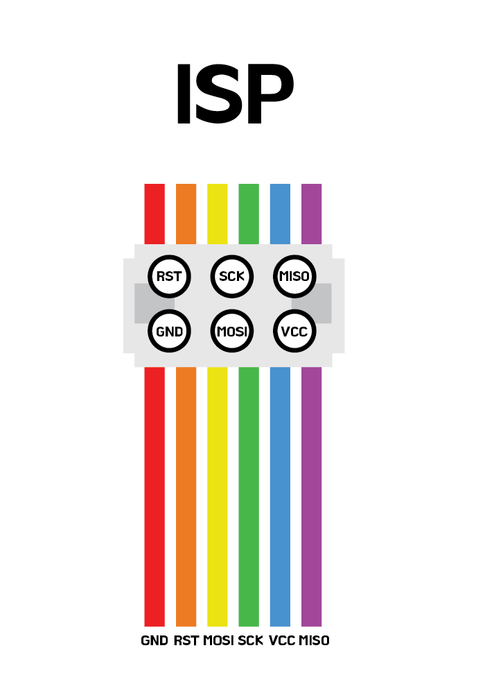
 Make sure to check the connections are to the correct pin.
Open Arduino
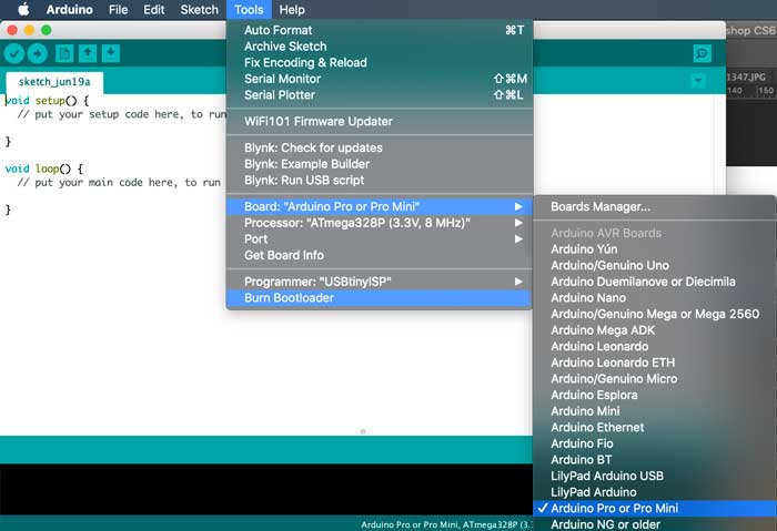 Burn Bootload as [Arduino Pro or Pro Mini]
And you are SET!
Burn Bootload as [Arduino Pro or Pro Mini]
And you are SET!
Trouble
 I used manicure to mark which pins are GROUND and VCC.