16. Interface and application programming
Individual assignment
Write an application that interfaces a user with an input &/or output device that you made.
Group assignment
Compare as many tool options as possible.
Group Assignment
We all did the group assignment together. Few of us used Processing, one used Blynk, one PyQt5 and others planned to use MatLab or Python.
A comparison of the different programs below.
Blynk
Blynk supports hardware platforms such as Arduino, Raspberry Pi, and similar microcontroller boards to build hardware for your projects.
Blynk supports the following connection types to connect your microcontroller board (hardware) with the Blynk Cloud and Blynk’s personal server:
- Ethernet
- Wi-Fi
- Bluetooth
- Cellular
- Serial
The Blynk platform includes the following components:
Blynk app builder: Allows to you build apps for your projects using various widgets. It is available for Android and iOS platforms.
Blynk server: Responsible for all the communications between your mobile device that’s running the Blynk app and the hardware. You can use the Blynk Cloud or run your private Blynk server locally. Its open source could easily handle thousands of devices, and can even be launched on a Raspberry Pi.
Blynk libraries: Enables communication with the server and processes all the incoming and outgoing commands from your Blynk app and the hardware. They are available for all the popular hardware platforms.
The basic usage in Blynk is to control microcontroller with a smartphone. No coding is necessary on the phone side. The virtual pin blocks are given as drag and drop modules to witch Blynk virtual pins can be assigned. The coding is done on the microcontroller side.
Hello world with Blynk from the microcontroller to Phones Blynk app monitor looks like this:
Blynk.virtualWrite(V1,"Hello World!");// Print a string
PyQt5
Qt is a set of cross-platform C++ libraries that implement high-level APIs for accessing many aspects of modern desktop and mobile systems. These include location and positioning services, multimedia, NFC and Bluetooth connectivity, a Chromium-based web browser, as well as traditional UI development.
PyQt5 is a comprehensive set of Python bindings for Qt v5. It is implemented as more than 35 extension modules and enables Python to be used as an alternative application development language to C++ on all supported platforms including iOS and Android.
PyQt5 may also be embedded in C++ based applications to allow users of those applications to configure or enhance the functionality of those applications.
Hello world widget with PyQt5:
import sys
from PyQt5.QtWidgets import QApplication, QWidget
if __name__ == '__main__':
app = QApplication(sys.argv)
w = QWidget()
w.resize(250, 150) w.move(300, 300)
w.setWindowTitle('Hello World')
w.show()
sys.exit(app.exec_())
Python
Python is an interpreted, high-level, general-purpose programming language used for developing both desktop and web applications. Python is also used for developing complex scientific and numeric applications and its design philosophy emphasizes code readability with its notable use of significant whitespace.
A simple program for addition and calculating savings in Python is presented below :
# Create a variable savings
savings = 100

# Create a variable factor
factor = 1.10

# Calculate result after 7 years
result = savings * (factor ** 7)

# Print out the result
print (result)
Hello world is simple or you can save it in a variable as above and print it:
print(“Hello, World!”).
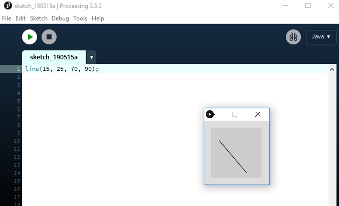
Processing
Processing is a flexible software sketchbook and a language for learning how to code within the context of the visual arts. Since 2001, Processing has promoted software literacy within the visual arts and visual literacy within technology. There are tens of thousands of students, artists, designers, researchers, and hobbyists who use Processing for learning and prototyping. Download website: is under this link.
- Free to download and open source
- Interactive programs with 2D, 3D, PDF, or SVG output
- OpenGL integration for accelerated 2D and 3D
- For GNU/Linux, Mac OS X, Windows, Android, and ARM
- Over 100 libraries extend the core software
- Well documented, with many books available
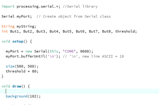
The Processing equivalent of a “Hello World” program is simply to draw a line:
line(15, 25, 70, 90);
it will draw a line in a window
Individual assignment
For individual work, I will use Blynk.
For this week assigment hardware I used mobile phone ESP32 and my BuckArdu. BuckArdu is a buck regulator board based on ATTIny44 that I build in the Input and Output weeks.
The idea is to use ESP32 as Blynk bridge. Into BuckArdu there is blue LED connected into the output. The output voltage is controlled by the BuckArdu’s PWM value. The PWM value is then controlled by the ESP32 with serial data. The PWM value is set from the mobile phone with the Blynk app. As the ESP32 is connected to internet via wifi,the blue LED can be controlled from anywhere in the world if there is a connection to the internet.
Blynk
Blynk is one of the easy-of-use mobile UI environments. Other similar is Ubidots In Blynk there are two sides to work with. The Phone app and the microcontroller code side.
Phone side.
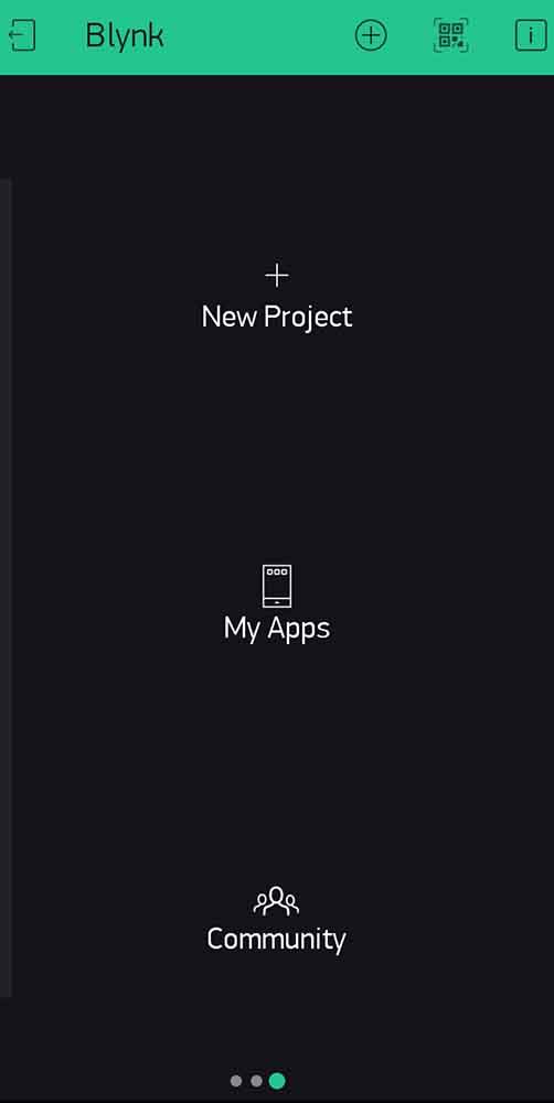
First Blynk is installed from the Play store. After installation, an account is required to register for the use.
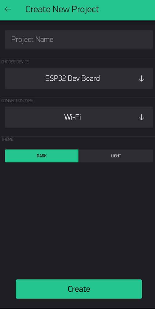
After registration, a new project can be created by pressing the New Project button.
From the New Project creation page, the IoT device can be selected and also the connection type.
For internet connected project the program sends an authentication code to the registration mail. This code is used in the microcontroller code to identify the user.
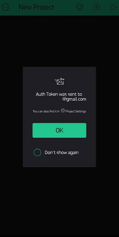
After this, the blank project page is created.

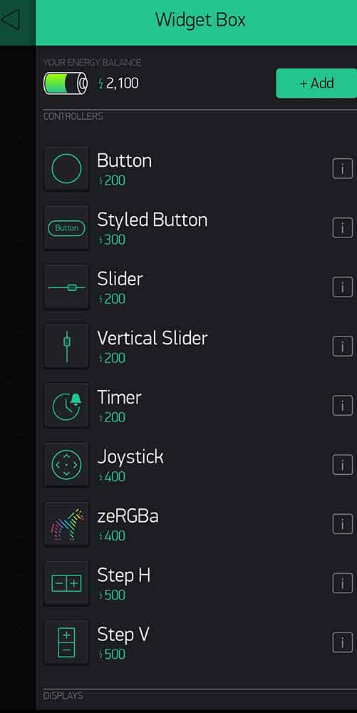
From the widget box, different buttons and functional widgets can be added.
The widgets are the main way to interact with the microcontroller. The widged’s are signed to virtual pins. Virtal pin is Blynk’s interface pipeline to address commands from phone to microntroller side. Any manipulation of virtual pin is seen by every widged and microcontroller assigned to that virtual pin.
From the widget, the used virtual pin is selected. The Widget controls the assigned virtual pin and the microcontroller side is coded to interact to same virtual pin.
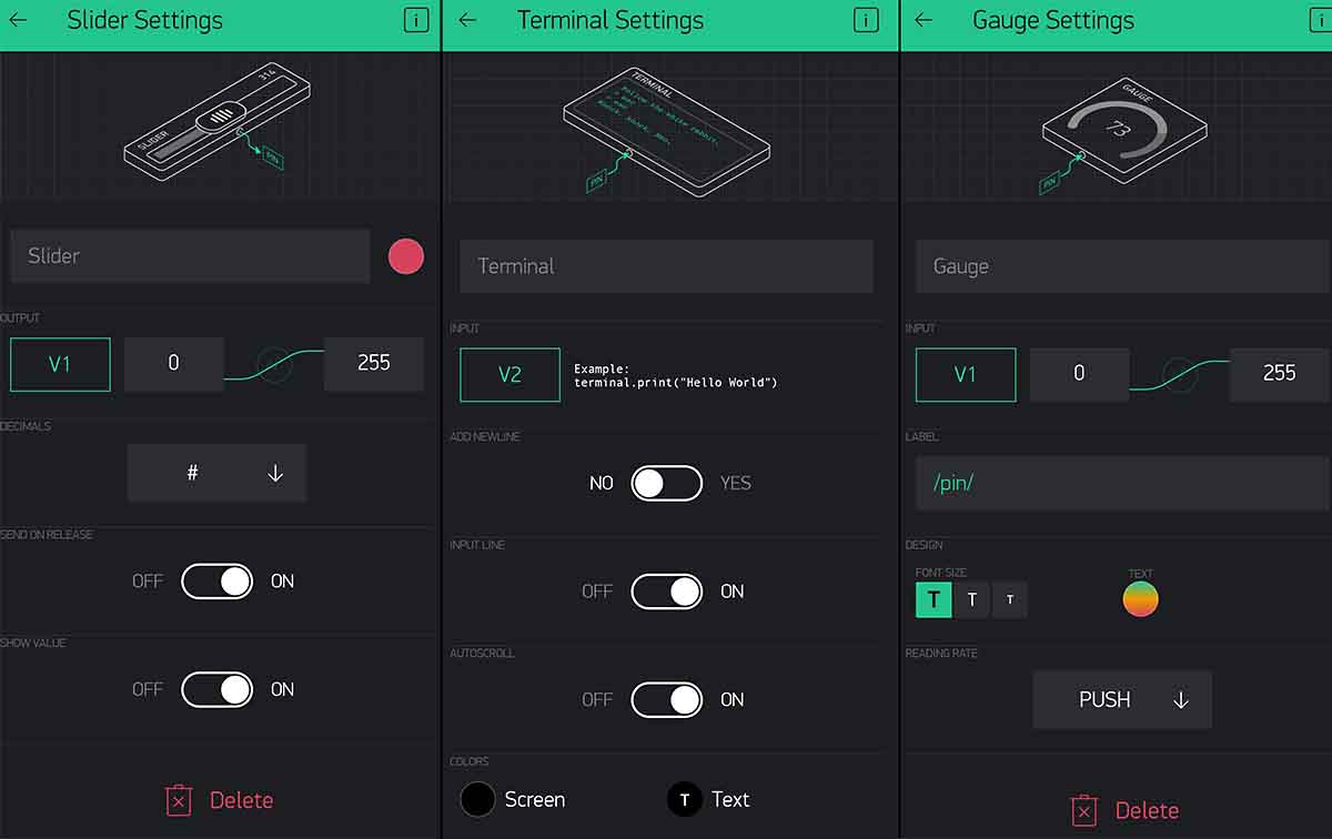
For this project the Slider, Terminal and Gauge are selected.
The Slider and Gauge are set to Virtual pin V1 and the range from 0 to 254 for 8-bit PWM controlling. The value of the V1 pin is set by the Sider. Gauge then reads the set value from the ESP32 side and displays the value in a numeric and in the gauge graphics. The gauge color is selected to change depending of the displayed value.
Terminal widged is used to pass feedback from the ESP32 to check the set PWM value. The Terminal reports back the status of the ESP32 on startup and the set PWM value on virtual pin V1 update. The data to Terminal is passed trough Virtual pin V2.
Video of the UI environment.
Microcontroller side.
The microcontroller side consists of ESP32 and The BuckArdu
The ESP32 code includes the Blynk library. It listens to the commands from the Blynk server from the Virtual pin V1 and passes it through to the serial. It also passes the current value to the V2 pin terminal.
Code for the ESP32
#define BLYNK_PRINT Serial             // The serial print.

#include <WiFi.h>                        // Wifi libaries
#include <BlynkSimpleEsp32.h>            // Blynk libaries.

#define AUTH                    "****"  //auth code from blynk goes here.
#define WIFI_SSID               "****"   // Wifi SSID
#define WIFI_PASS               "****"  // Wifi Password
WidgetTerminal terminal(V2);            // set the Terminal vidged for pin V2


BLYNK_WRITE(V1)           // Command for the Virtual pin V1. This code gets executed when an update comes from pin V1.
{
  int pinValue = param.asInt();    // assigning incoming value from pin V1 to a variable

  terminal.println(pinValue);             //The pin value is echoed back to the terminal
   terminal.flush();                       // The terminal information is send and shown in the Blynk app.
  Serial.print(pinValue);                    //Send the desired value to the serial (TX(GPIO 0) ,RX(GPIO3)) pins.

}


void setup() {
  WiFi.mode(WIFI_STA);              // set the wifi to station mode.
  Serial.begin(9600);               //Start the serial

#if defined(USE_LOCAL_SERVER)
  Blynk.begin(AUTH, WIFI_SSID, WIFI_PASS, SERVER);
#else
  Blynk.begin(AUTH, WIFI_SSID, WIFI_PASS);
#endif
  while (Blynk.connect() == false) {}                       /// This everything connects to the access point.

  /******** READY **************/
  terminal.print(F("# Blynk v" BLYNK_VERSION ": "));

  terminal.println(F(" FabAcademy Device started"));
  terminal.flush();                                     // This tells to the Blynk terminal that the microcontroller side is ready.
}


void loop()
{
  Blynk.run();    // Chill. Wait for the inputs.
}
The BuckArdu takes the serial input as parseInt to get the needed 3 digits and updates the PWM duty cycle.
Code for the BuckArdu
#include <util/delay.h>     // Library to add delays. Necessary for blinking.
#include <avr/io.h>         //Library to handle avr inputs and outputs
#include <SoftwareSerial.h> // Serial libary
SoftwareSerial mySerial(0, 1); // RX, TX    // Pins fot the Serial

const int ledPin =  8;          // the number of the LED pin ( = ATTiny pin 5)
long incomingByte = 254;        // Setup for the PWM value.

void setup() {
  mySerial.begin(9600);                       // start the serial.
     pinMode(1, INPUT);                      // set the RX pin to input.
  DDRB = DDRB | (1 << PB2);                  // DDRB Port B Data Direction Register. Selects direction of pins
                // In this case PB2 is an output

//these are for the PWM output,using the timer0:
DDRA      |=      (1<<DDB2);                           //setting the PWM pin to output.

TCCR0A    |=      (1<<WGM01);                            // set for Fast 8-bit PWM mode
TCCR0A    |=      (1<<WGM00);                             // set for Fast 8-bit PWM  mode
TCCR0A    |=      (1<<COM0A1);                        // Set OC0A on Compare MatchClear OC0A at BOTTOM (inverting mode). Driving N-channel mosfet.
TCCR0A    |=      (1<<COM0A0);                    // Set OC0A on Compare Match Clear OC0A at BOTTOM (inverting mode) Driving N-channel mosfet.
TCCR0B    |=      (1<<CS00);                     //  clk0/O/1 (No prescaling)try to go afap. this gives a freguency of 20 000 000hz/256= 78 125hz
TCCR0B    &=     ~(1<<CS01);                          //set CS01 to 0.


OCR0A = incomingByte ;                                   // start the PWM signal from 254 value (0-254 because of the 8-bit mode. 254 because of the inverted mode.)  P-MOSFET is off and no power is going through.

}

void loop() {


  if (mySerial.available() > 0) {           // when serial recieves somethin execute this code.

   incomingByte = mySerial.parseInt();         // take the buffered serial data and parse it into Int datatype.
    pinMode(1, OUTPUT);                     // open line to write
     mySerial.println(incomingByte);        //Echo the recieved data back
      pinMode(1, INPUT);                    // close the  line


OCR0A = incomingByte;                       // Update PWM duty cycle.

  }
}
The setup was wired and tested for working.
In the video when the Slider is set toa value. the Gauge widged updates to show the value. In the Terminal widged the set value is also shown. And the blue LED brightness is changed according the set slider value.
Reflection
This week assignment was nice addition towards the final project. Blynk might be one way to control the Final project lamp. Also a good lecture the caveats of the serial data types.
In the programming there were some initial problems with the ways serial commands are handled. The normal use of Serial.read() reads only the first byte out of the serial buffer. This limited the first use to only receive reliably the digits from 0 to 9. After some searching I found out about Serial.ParseInt() commands that reads the buffer into int type integer that can be used as PWM value as is. This method does limit the update frequency of the PWN value to the Serial timeoutvalue. But as the update interval of the Blynk app is 1 second, there will not be any interference from this timeout value.
All the necessary files can be found on my gitlab page
The Blynk widged can be cloned to any Blynk app by scanning the QR-code with the Blynk app.