17. Machine design
Group assignment
The complete report can be found here.
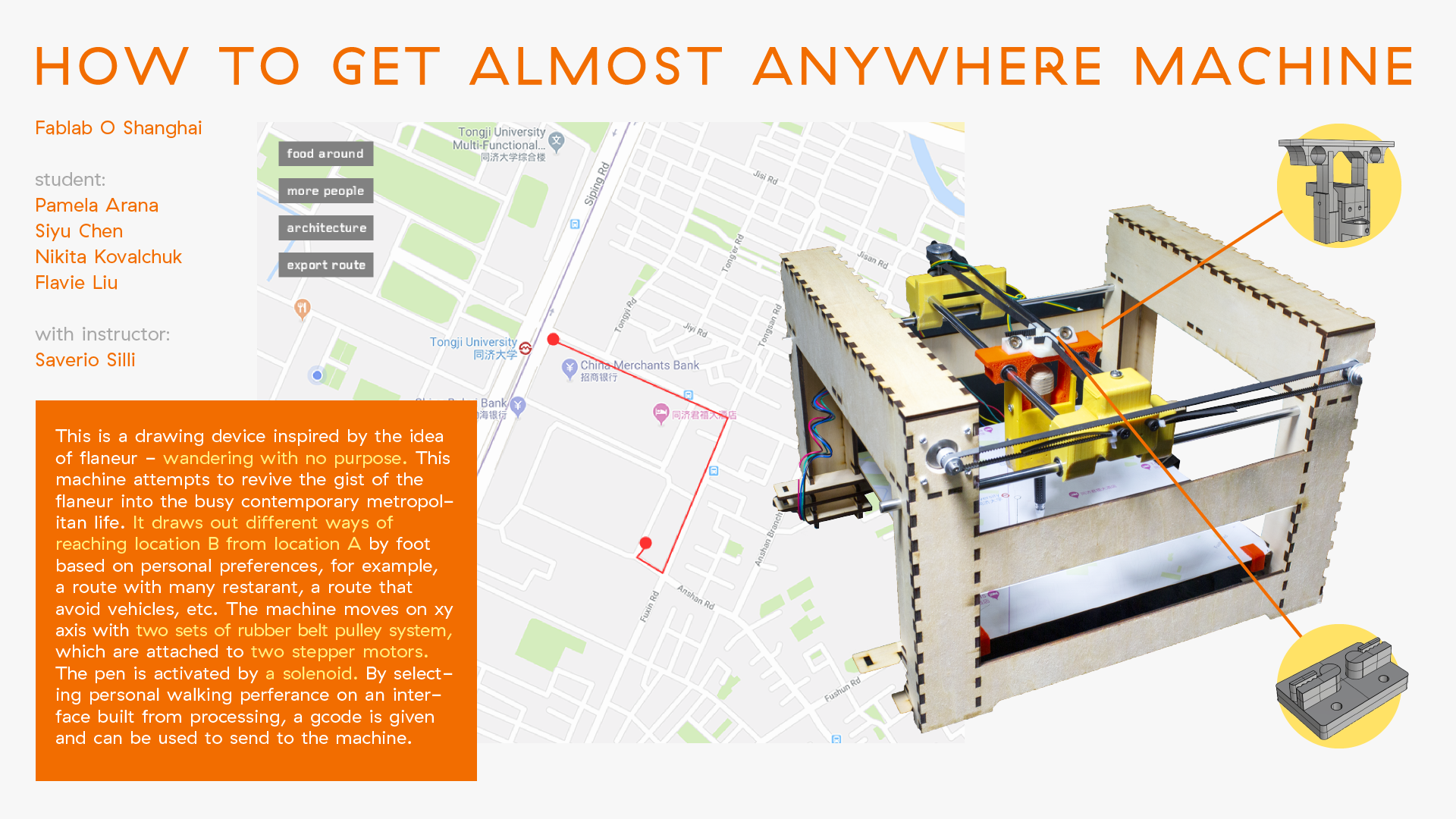
The idea for the project was to create a 2-axis + 1 machine that will draw the route on the map. Potentially it can be used as the guide on the exhibitions or events. The user asks the place, where he or she needs to go, and the machine draws the route on the physical map.
We have worked as the team to create it. Most of the effort and contribution came from my classmates:
Also, big thanks to Saverio Silli as our instructor.
Individual assignment
According to our agreement with classmates, I was responsible for creating top sliding parts for rails and solenoid-based pen actuator. The final result was the following:
I have created the following parts:
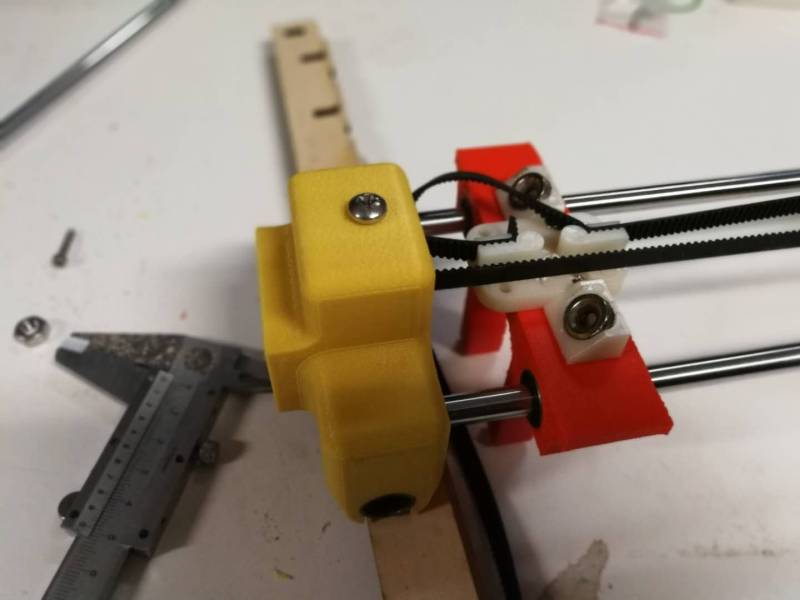
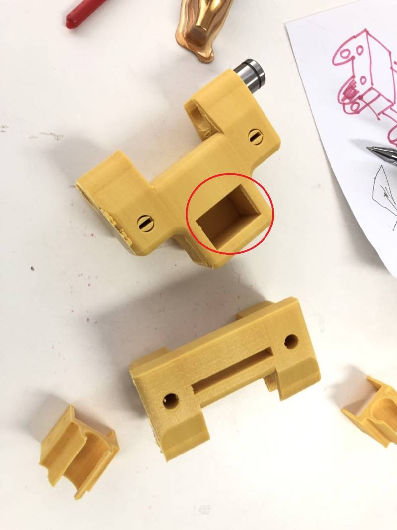
Yellow plastic rail holders:
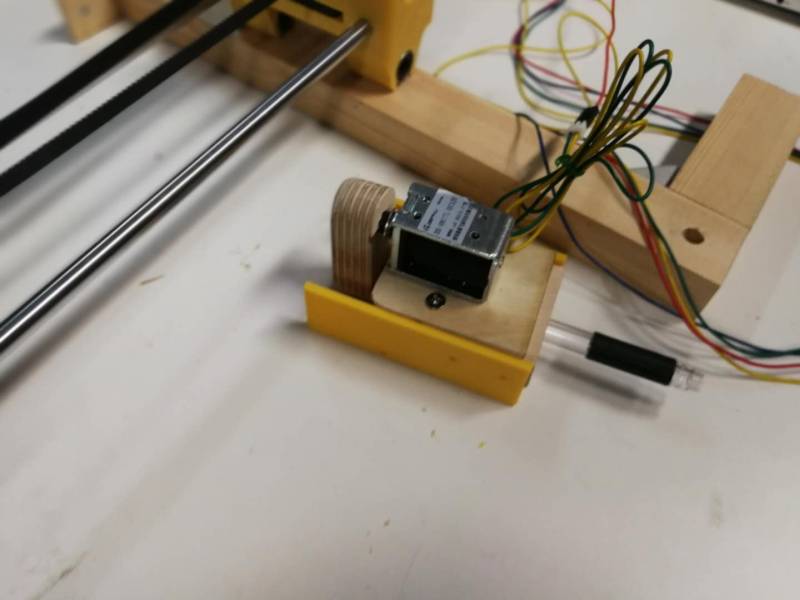
Solenoid-based wooden pen actuator
The initial prototype of the machine was like this.
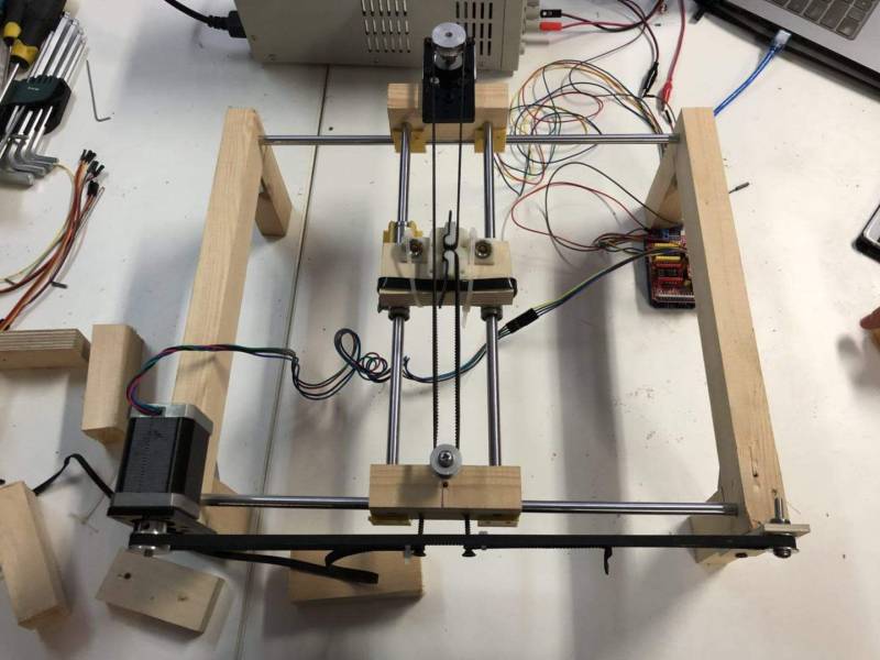
It was working. However, it was not good looking, and it was not rigid enough. I supposed to create the structure that should not fluctuate, should provide smooth sliding on the rails and should fit the rest of the machine structure and fit the holder for pen actuator.
Design of the rail holders
Before I began the design process, I have agreed on the measures with my classmates:
- The places for the rollers of the stepper motors
- The heights and requirements for pen actuator holder
- The distances between rails
Also, I have decided that it would be good to have additional stiffness for the place of the roller for the top belt. Therefore, I have decided to create “the cave,” where the rollers screw has two points of connection.
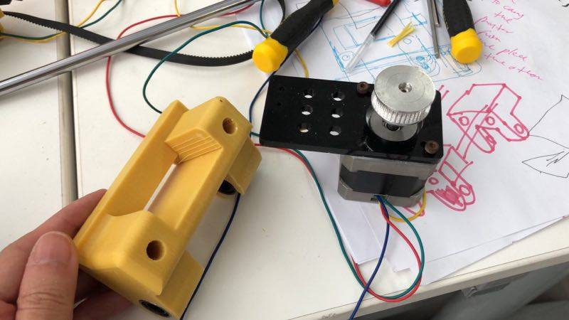
The second rail holder is also the holder for the stepper motor. Therefore, it should have strong connection points for the motor. I have designed the hole and bigger place that fit the motor’s holder perfectly. This solution provided the required stiffness.
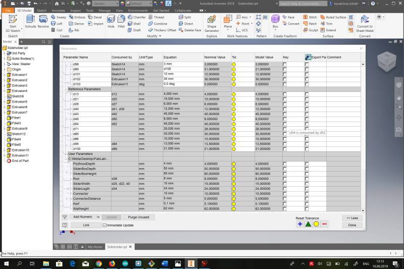
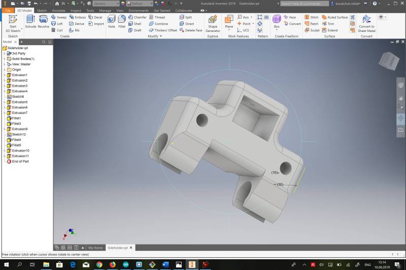
I have used Autodesk Inventor to design the parts, and I have created a parametric table to be able to change any parameters if needed.
I also applied fillet settings to all angles to make the design smoother.
Design of the solenoid actuator
This part was the hardest one. At first, I have decided to create a more complex structure out of plywood. I also used Autodesk Inventor and cut all parts with the laser cutter.
The result was like this.
It also supposed to be driven by a solenoid. It had leverage inside. Therefore, a small movement of the solenoid supposed to cause more significant movement of the pen holder. However, the solenoid was not powerful enough to move the structure, and the connections were not smooth enough. Therefore, the whole device was not working correctly.
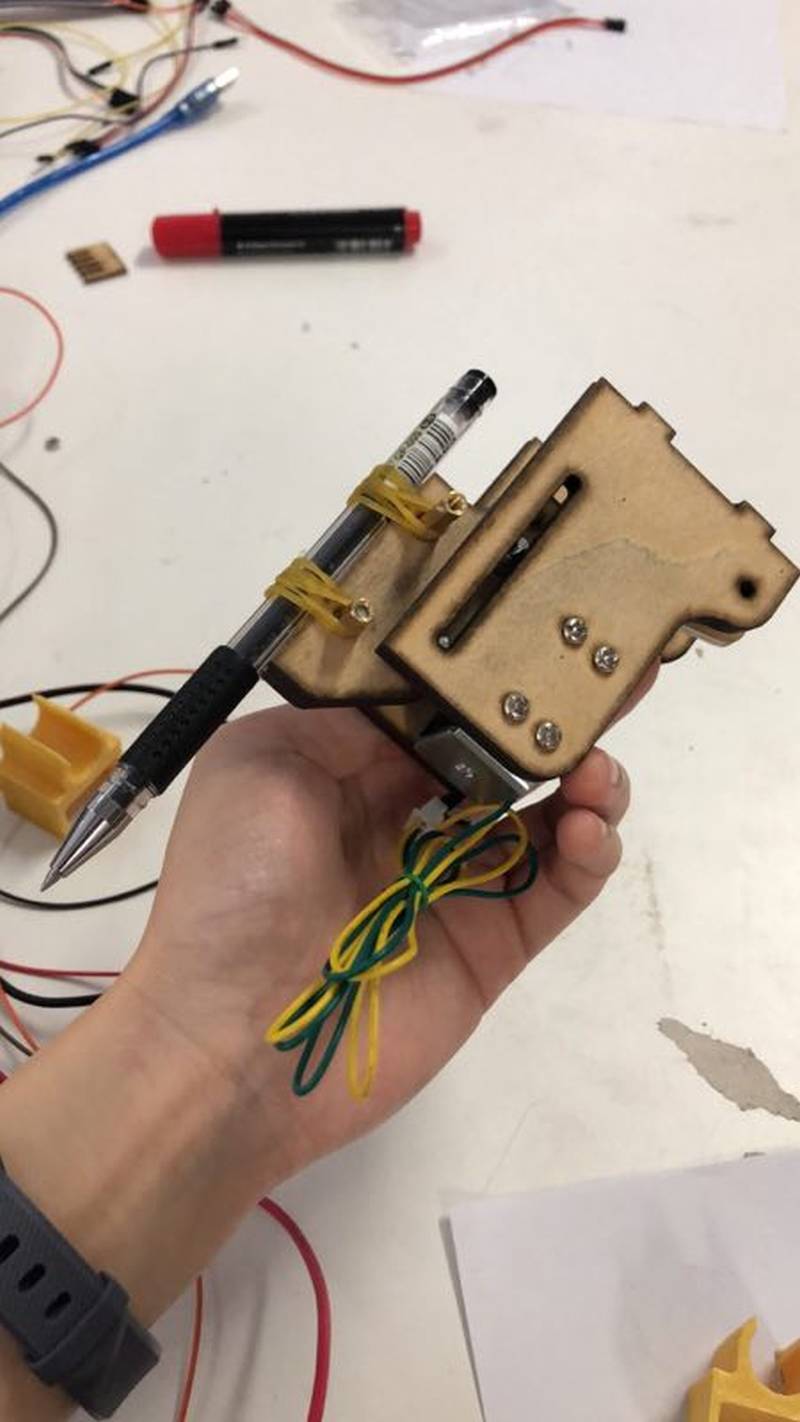
As a result, we have decided to use a simple structure. This design was the collaboration between Pamela and me.
The principles of the devices are the following:
- it has straightener with a slightly wider diameter than the pen to provide stiffness
- it should be lightweight to allow the solenoid to move the pen easily
- it should fit the whole machine structure
- there should be enough space for the solenoid ventilation
The created structure was entirely made of wood and fully complied with the requirements.
I have used saw, drill, and screws to create it. Unfortunately, I have not taken pictures of the process.
Files: