_week 15+17
mechanical design & machine design
So guessing by the title you will know these weeks were about building a machine... and yes! together as a team we had the task to build a machine during week 15 and week 17 of the course.
Week 15 was focused into prototyping the machine and week 17 into automating the mechanism, but as all
our team was busy in Seoul attending FAN5 (FabLabAsiaNetwork), during the
week 15 we focused more our efforts into eating kimchi and BBQ rather that working on the machine, hey!
but we did our brainstorming in the streets of Seoul while having some street food, so... we did work
during week 15.
Anyhows, we condensed into one week both weeks, and we are alive and so our machine.
Here's a bit of a background of our machine.
Group assignment
We started these assignment with a brainstorming, I mentioned we did one in Seoul, but prior to that one we also had a session of brainstorming of very general ideas for the machine.
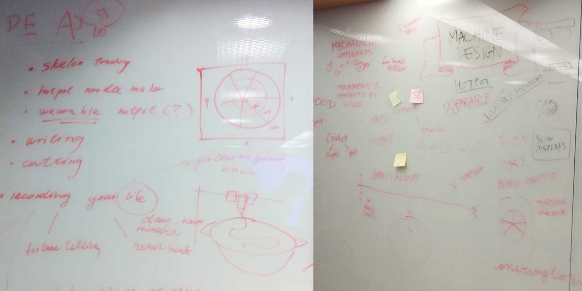
From this first session we decided we would build a useless machine, for what... we didn't know then yet.
It was just during FAN5 that we decided what we were going to build, and the ideas was born of building a
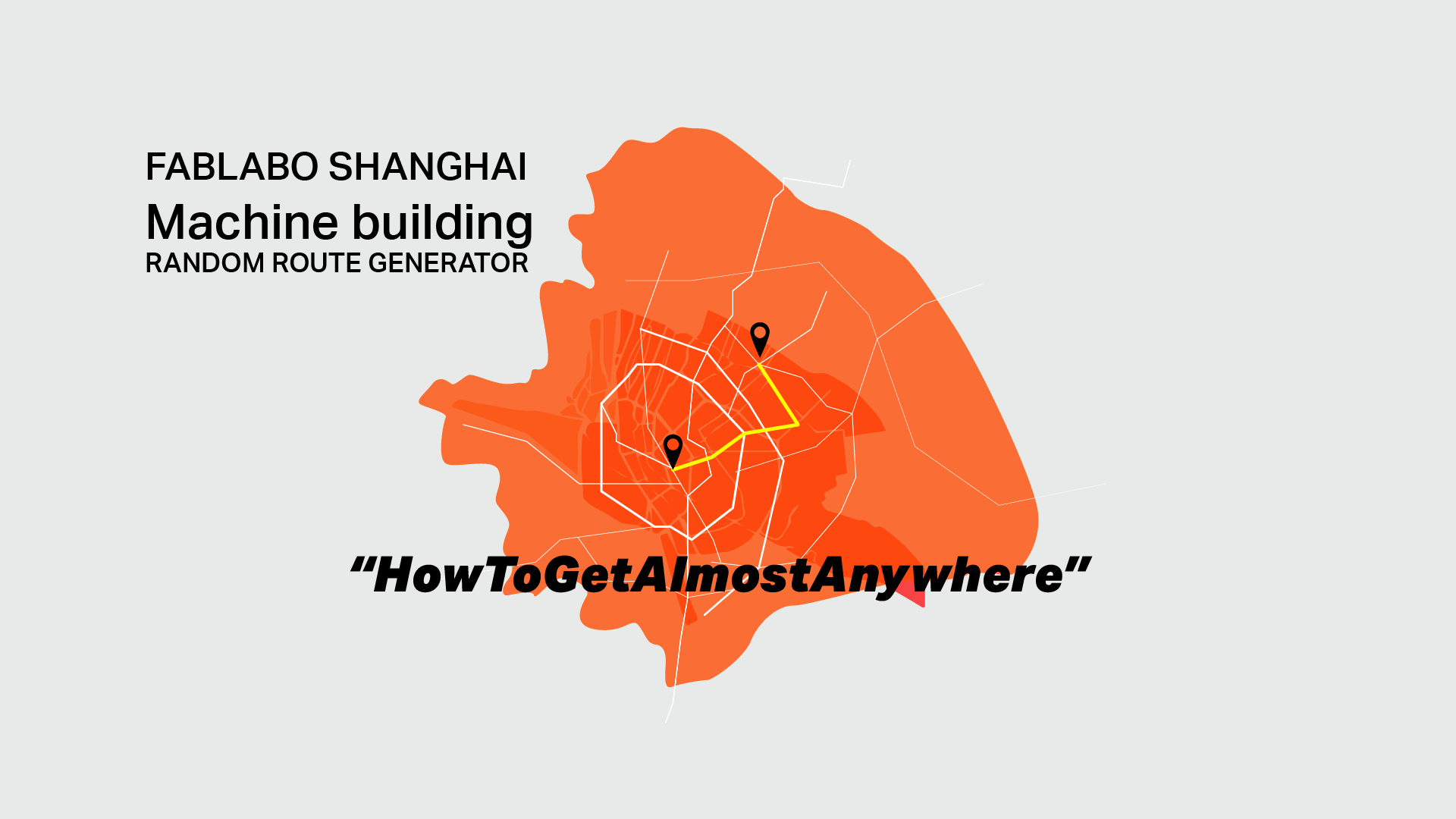
RANDOM ROUTE GENERATOR MACHINE.
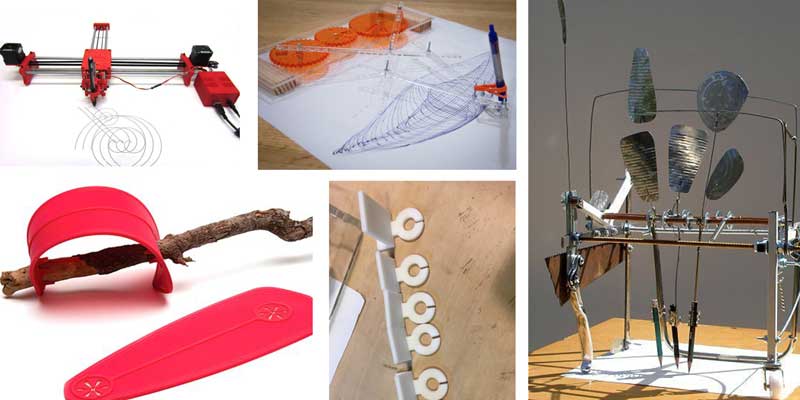
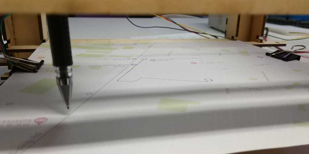
What is it? the idea is a plotter that generates random routes in a map, and these routes are printed in
a physical map so that the user can take this map and follow the route. The routes will change according
to different variables. In the beginning we thought that the user could interact with the machine by
giving inputs to it, such as what the person wants to avoid or wants to see along the way, and the
machine would generate a route according to those inputs/variables.
And this is how the idea was born:
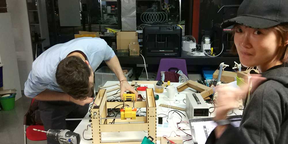
We built the machine among our Lab team, we worked all together during each step of the process and each
pf us focused in different tasks among the project development.
On my site I will document the parts were I contributed and you can check out each of my classmates
documentation to read more about the project and their contribution to the machine. Also we have our Lab
page were we have a summary of the machine building, and ofc I have to mention our instructor Saverio
helped us during the project.
_Liu Xiaofei
_Chen Siyu
_Nikita
Kovalchuk
And our Lab documentation check it out HERE
Individual contribution
_MACHINE PROTOTYPE
Together with my classmate Flavie (Liu Xiaofei), we started by brainstorming possible structures for the
machine, and we started by researching online for ideas and existing projects from previous years
students.
As we new we were going to build a plotter we tried to look for similar projects to start figuring out
the mechanism needed and the components of the printer itself.
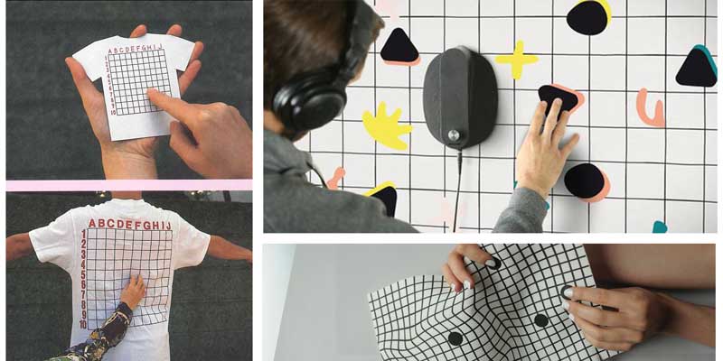
We thought the plotter could have an area were the user inputs the variables by touching a path or surface, this was an initial idea for the part of programming and interface. Our final outcome doesn't integrate this idea yet but we may develop it further if we have time afterwards.
As I mentioned before, we also researched previous years students and we found a project from 2016 from Lab Ajaccio that seemed very interesting the structural part.
From here we started to brainstorm as well the components of the printer itself. And we found out some inspiration for our machine:
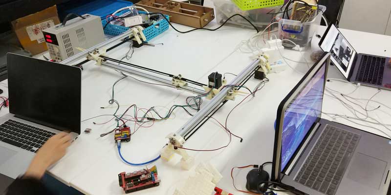
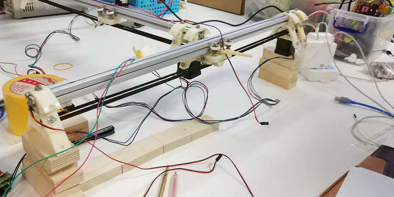
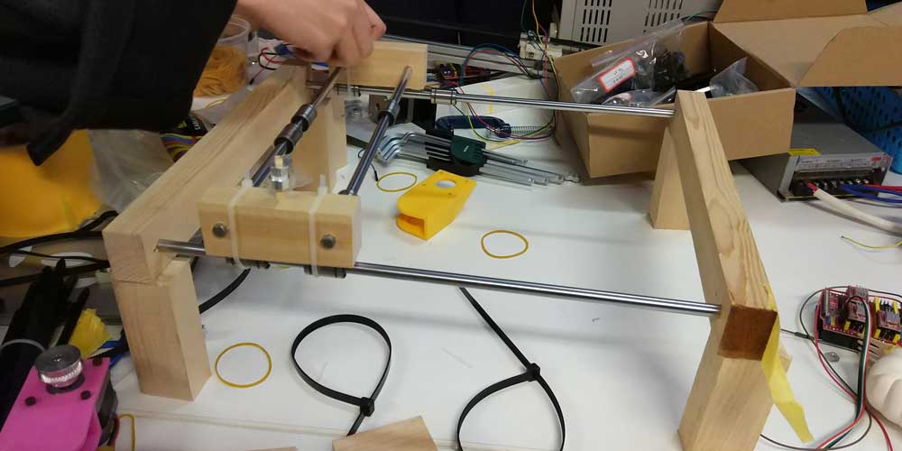
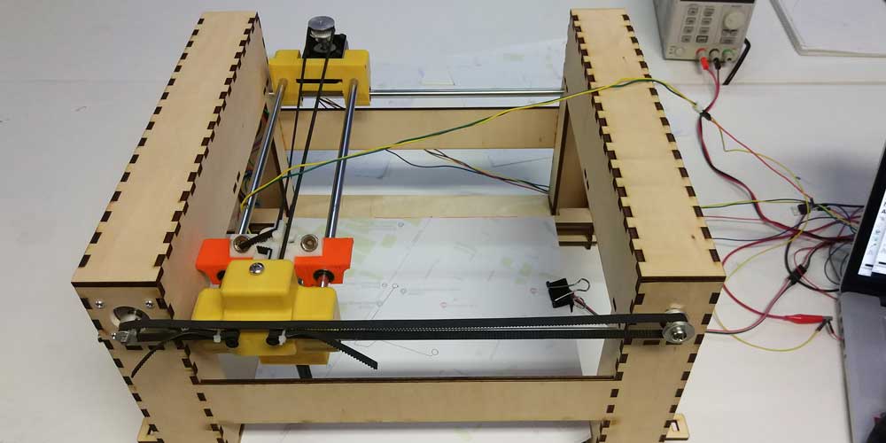
After this together with all the team we started building our first prototype out of a Delta printer that
was no longer working in our lab.
We dissambled it and did a prototype of the structure using all it's components, this exercise helped us
a lot to understand how to control X and Y axis and how to use a CNC shield which is what
we decided we would use to automate our machine.
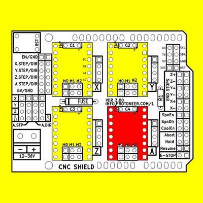
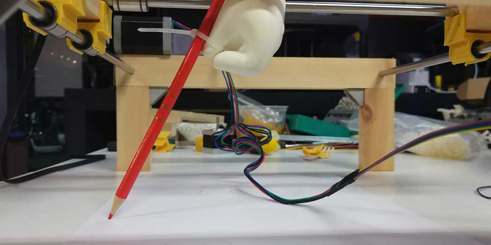
The CNC shield that we are using works together with an Arduino Uno board, is mounted on top of it and
then you use something called shields that are pinned into the axis you will be using (X,Y,Z), you have
4 ports as you can repeat any of the axis, the extra port is called "A" on the board (the red one on the
pin out).
For our first test we used only X and Y axis to test the CNC shield and understand how it works.
After wiring up all, we need to provide 12V to motors, so we used a battery supplier to regulate the
volts we needed.
After this we connected the CNC shield into the computer and we had to do the following steps on this
order:
_1 In Arduino you have to add a GRBL library so that it can work as a CNC shield and can control the stepper motors you will plug into it. And you should run inside examples>grbl>grblUpload. This is how the code looks like:
/***********************************************************************
This sketch compiles and uploads Grbl to your 328p-based Arduino!
To use:
- First make sure you have imported Grbl source code into your Arduino
IDE. There are details on our Github website on how to do this.
- Select your Arduino Board and Serial Port in the Tools drop-down menu.
NOTE: Grbl only officially supports 328p-based Arduinos, like the Uno.
Using other boards will likely not work!
- Then just click 'Upload'. That's it!
For advanced users:
If you'd like to see what else Grbl can do, there are some additional
options for customization and features you can enable or disable.
Navigate your file system to where the Arduino IDE has stored the Grbl
source code files, open the 'config.h' file in your favorite text
editor. Inside are dozens of feature descriptions and #defines. Simply
comment or uncomment the #defines or alter their assigned values, save
your changes, and then click 'Upload' here.
Copyright (c) 2015 Sungeun K. Jeon
Released under the MIT-license. See license.txt for details.
***********************************************************************/
#include
// Do not alter this file!
_2 After running the code in Arduino, install the Universal GCODE sender (UGS Platform) software, which will let you control the motors and input a GCODE.
--HERE ADD VIDEO OF THE FIRST PROTOTYPE WORKING---
_MACHINE SECOND PROTOTYPE
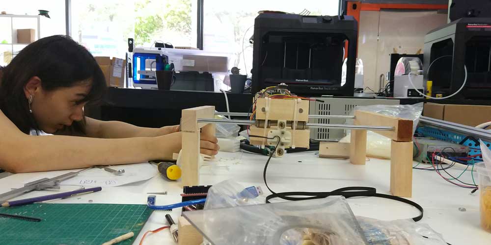
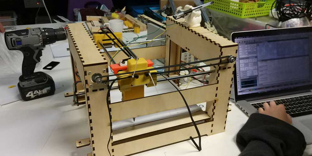
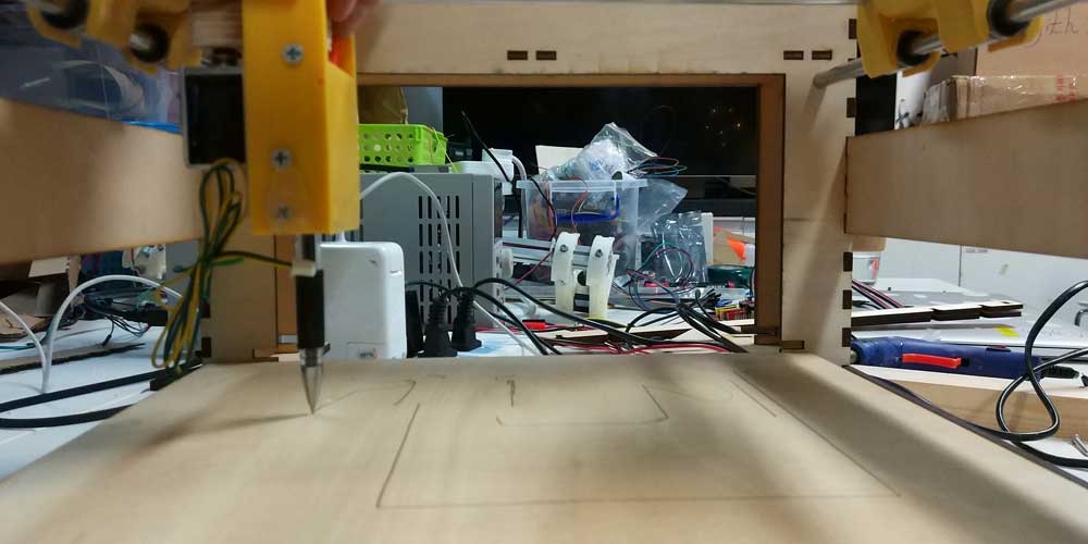
After understanding what axis we needed, how to control them, together with Siyu and Flavie we started to work on the structure of our machine considering all the components and parts we needed to integrate and control.
We used material available in the lab, leftovers of other machines, scraps of wood and evenn a Mario hand we found on the trash, to build the structure of our machine.
--HERE ADD VIDEO OF THE FIRST PROTOTYPE WORKING---
This phase of prototyping is crucial, it helped us to understand what we needed, how to design it and what machines to use (laser cutter or 3D printer in our case).
At this point we split several tasks among the team. Mine was to design the structure of the machine itself, the frame.
_MACHINE STRUCTURE DESIGN
Having already a functional prototype I worked from there and decided what materials and machine to
use.
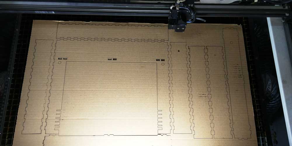
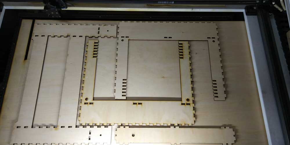
We decided to use plywood for the structure as we needed a solid body to hold all the components and to
use the laser cutter to cut out all the parts.
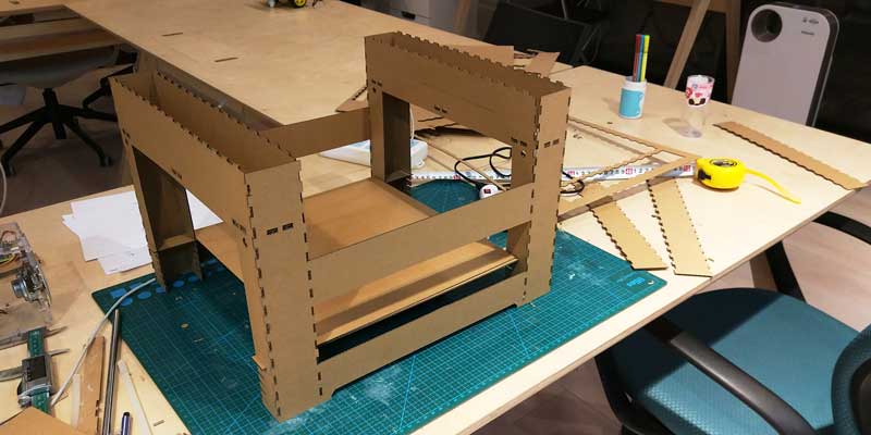
I started by drafting the general shape of the structure and then started prototyping the frame using
cardboard.
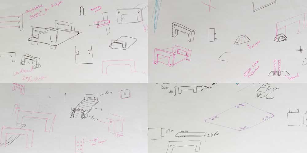
My initial idea was to have two separate frames what would be connected from below with a bar, so I started building the first iteration out of cardboard.
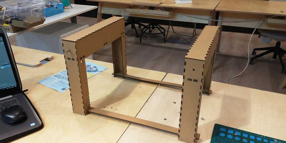
But then I soon realized that this type of connection from below, using a simple bar wouldn't hold all
the weight and might create unstability.
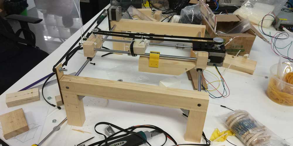
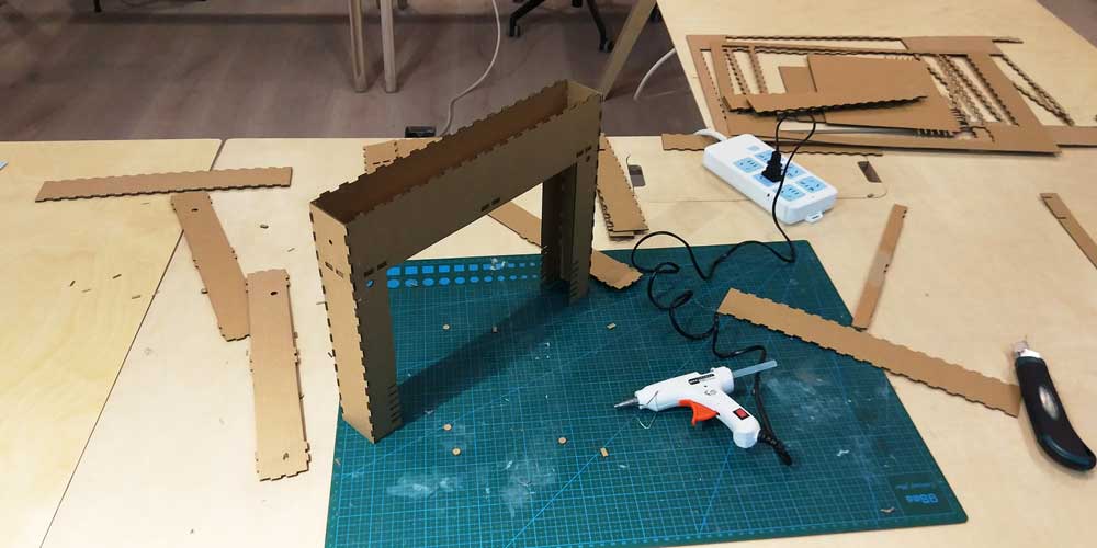
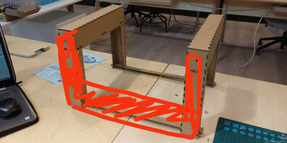
I wanted to keep the structure as open as possible so that the users could see better while the map was
printed either from the top or from the sides of the printer, but I realized I had to connect the two
frames by one of the sides, like this:
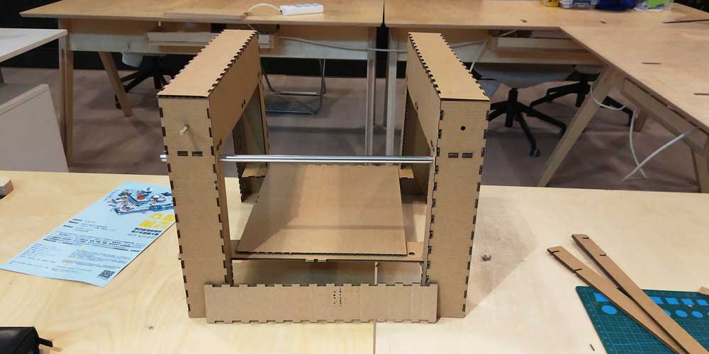
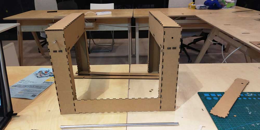
So I changed the structure and tested it using cardboard:
After this I updated the file as I was using a 3mm stock material thickness for my protoype, and changed it to 4.5mm plywood.
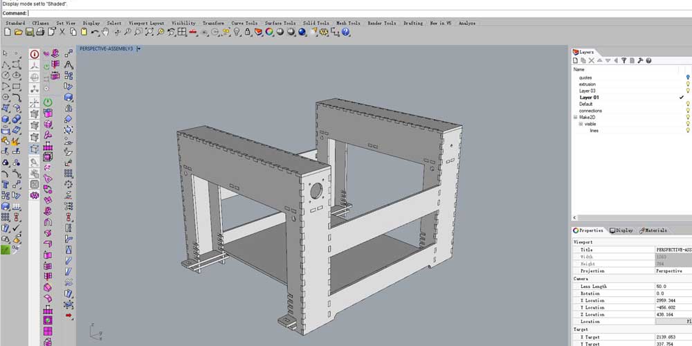
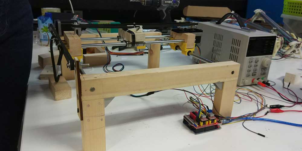
Here are the photos along the process of assembly with all the other components my teammates designed:
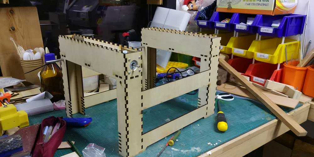
Below are the assembly instructions for the frame of the printer, and the explanaition of each part and what they are for:
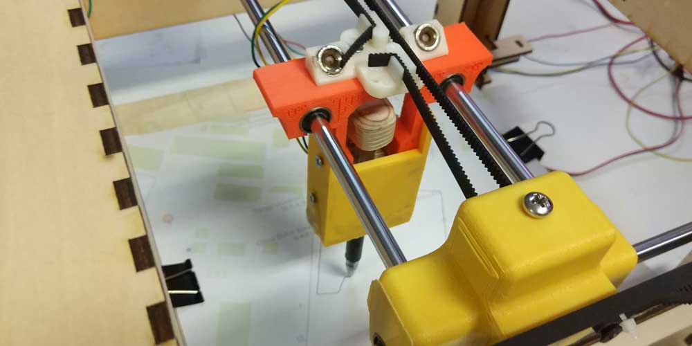
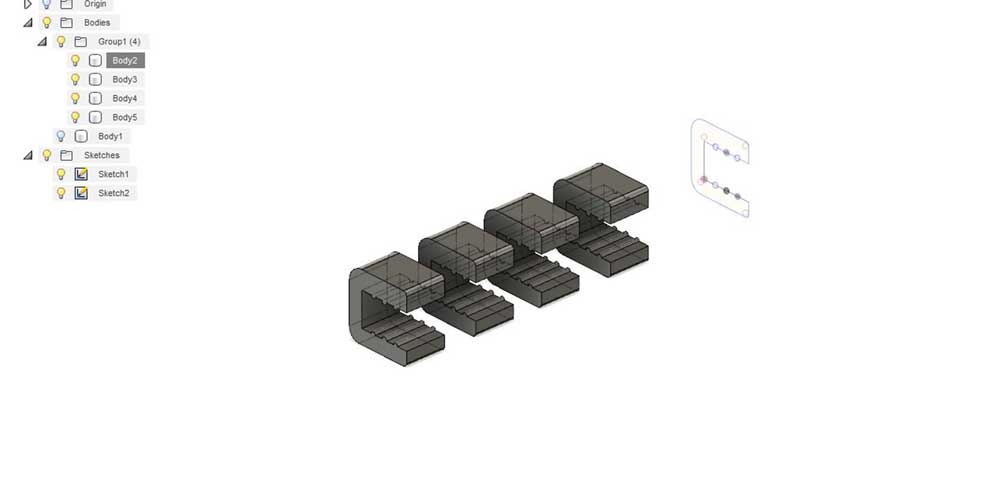
_BASE CLIP HOLDERS
I designed and 3D printed some clips to fix the board to the bars holders. I did the design on fusion 360, here is the process and outcome:
_VIDEO
Siyu, Flavie and me recorded the machine while working and then I edited the video assisted by the best
editor in town, Jose Salto.
We used Adobe Premiere Pro for the editing.
Here is the outcome of the video:
_FILES DOWNLOADS
_frame structure
_base clip
holders