7. Electronics design
Tasks for this week:
- Group assignment. Use the test equipment in your lab to observe the operation of a microcontroller circuit board. Done.
- Individual assignment. Redraw the echo hello-world board, add (at least) a button and LED (with a current-limiting resistor), check the design rules, make it, test it. Simulate its operation. Render it. Done.
Group assignment
For the individual assignment, we used oscilloscope to test the boards that we have made. The report is prepared by my classmate Pamela. Link to the report.
In particular, we used this tool to see the difference between a digital and analog signal that different electronic components can produce. For, example, after we have finished the Echo World board, we were able to monitor the signals that crystal produces for the MicroTiny chip. The purpose of this component is to help the microprocessor to measure time. It produces the signal with a certain frequency so the microcontroller knows that one second it should receive a certain number of signals. We used oscillograph to see the signal. On the monitor, we saw the wave that was continually produced by the crystal.
Individual assignment
The purpose of this assignment was to create our echo board. We were able to use Neil’s original design. But we were also required to add some additional component such as button and LED.
However, the most complex task was to program the board.
Draw the board
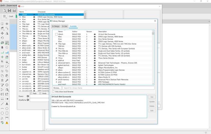
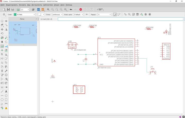
To draw my board, I have started from scratch. I decided to use Autodesk Eagle because I liked the interface and usability of this software. Also, it has a free version that is enough for our purposes. As an example, I have used this pattern (http://academy.cba.mit.edu/classes/embedded_programming/hello.ftdi.44.png) First, I have added all the components to the worksheet in Eagle.
Next, I have connected all the components according to the pattern and designed the scheme.
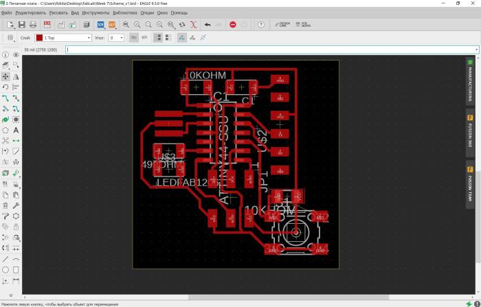
However, it is not enough to create an actual board. Designing the traces on the surface is necessary. Sometimes it can be tricky as the pattern can be complex and the design process can remind puzzle.
Test the design
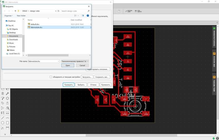
Ones the design is done. It is necessary to understand if it can be milled with the equipment that we have. I have used the rules provided by FabAcademy and uploaded these rules to Eagle.
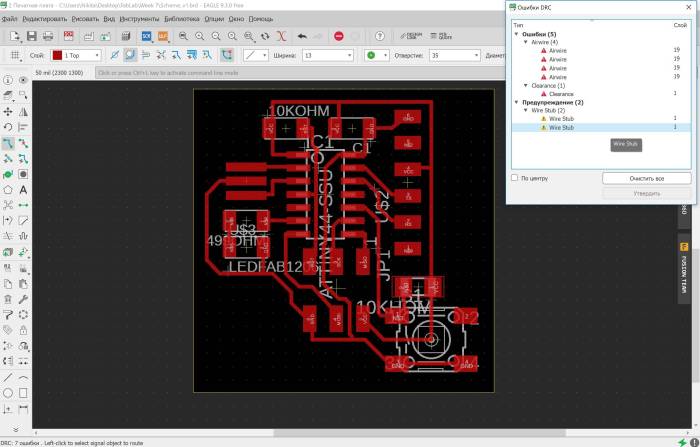
Then I run the checking process. The system has found some issues with the location on the traces.
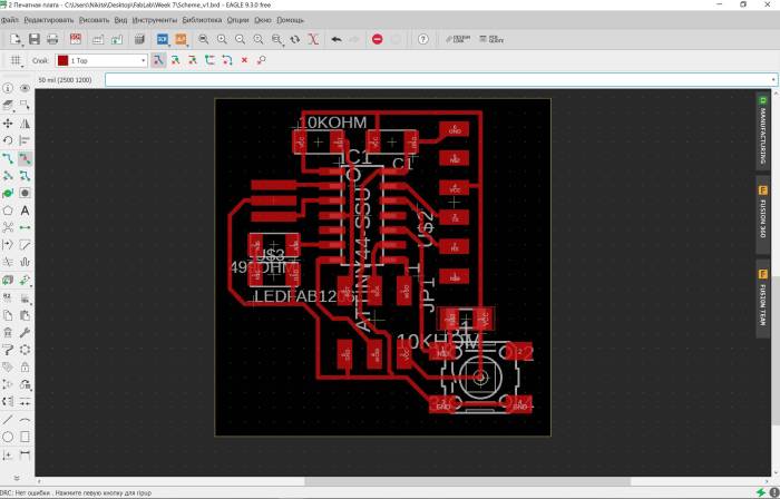
I resolved those problems and my final board design was this.
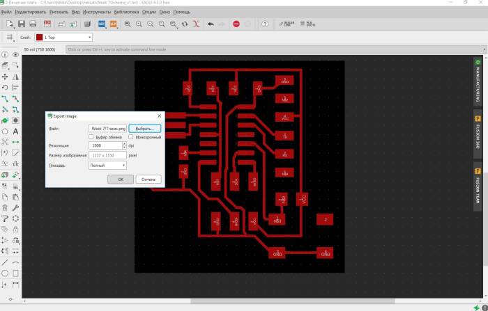
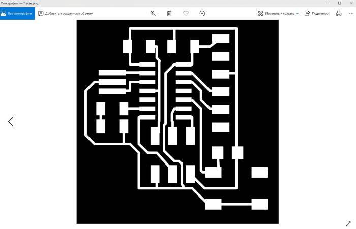
Then I prepared the PNG file that can be used to create the program for a milling machine. I hid all the unnecessary information and kept only traces.
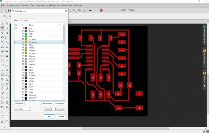
And save the pattern as a PNG file.
Mill the board and stuff it
Before I uploaded the resulted file into the program (fabmodules.org) to create the milling pattern for CNC machine, I have slightly edited the picture and added some design.
Also, I have created an outline pattern. Please see final files in the Files section.
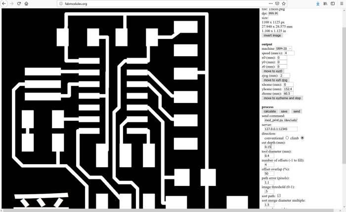
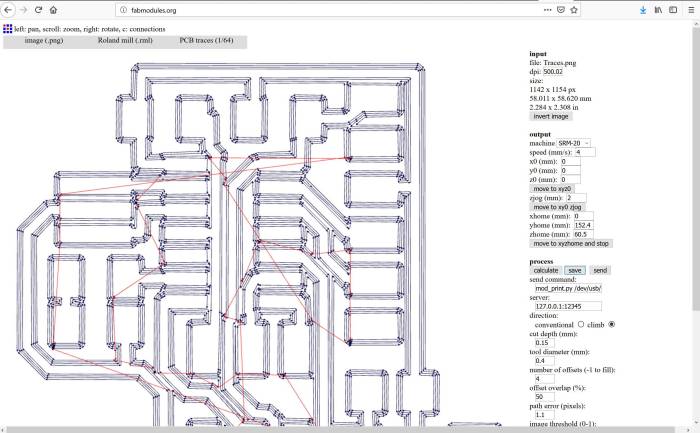
The pattern for the CNC machine was this.
After the files for CNC were ready, I have milled the board.
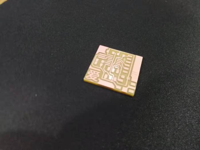
Ad stuffed it according to the scheme.
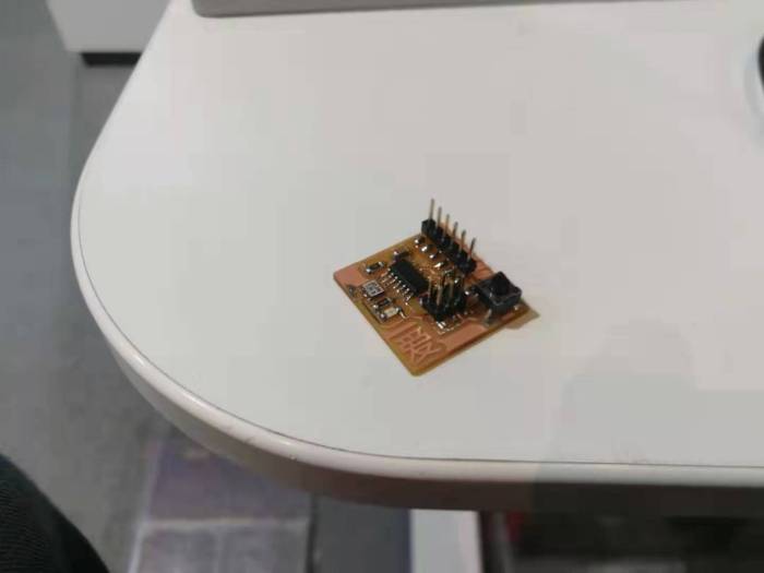
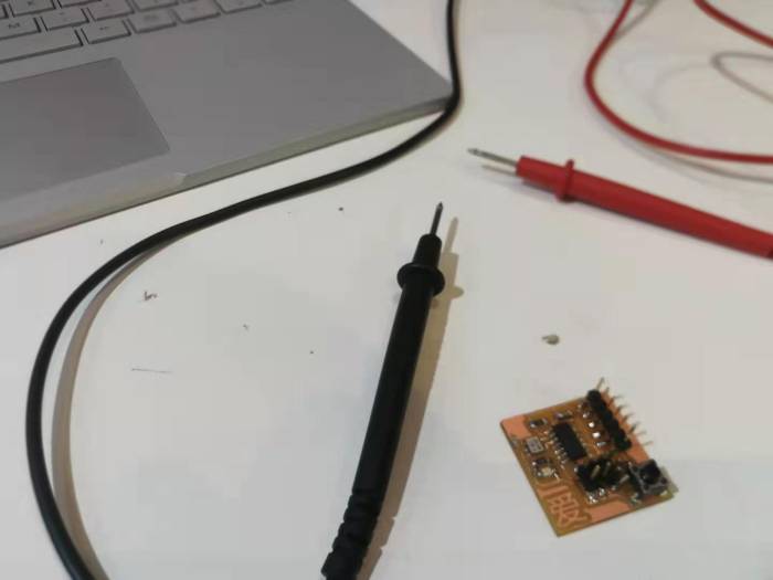
Test the board
Then I have tested the board if it has proper connections between components and no shortcuts.
Program the board
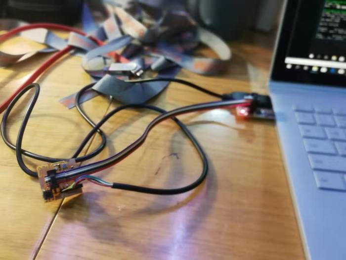
To program the board, I have used the FabISP programmer that I have created earlier.
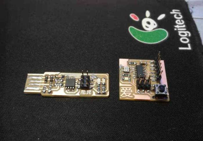
I connected the Echo board to FabISP and my computer with FTDI cable.
I have downloaded the programs provided by FabAcademy to my computer:
hello.ftdi.44.echo.c Link
hello.ftdi.44.echo.c.make Link
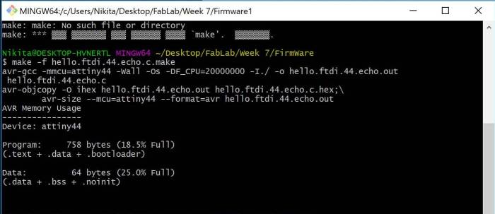
Then I located the folder in Bash terminal and run the program “make -f hello.ftdi.44.echo.c.make”
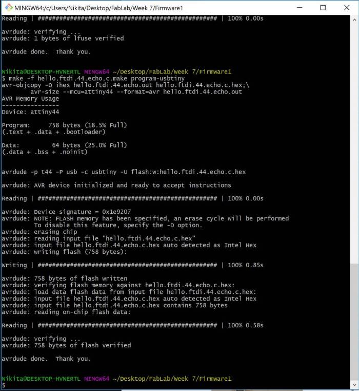
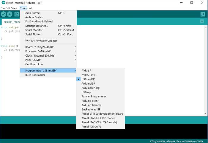
Then I run the program “make -f hello.ftdi.44.echo.c.make program-usbtiny-fuses” and “make -f hello.ftdi.44.echo.c.make program-usbtiny”
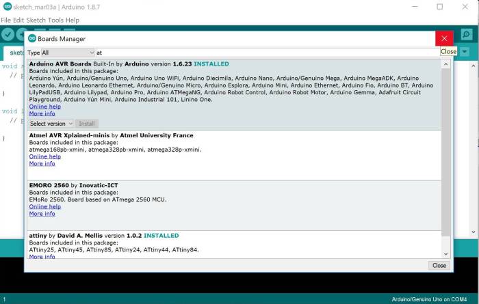
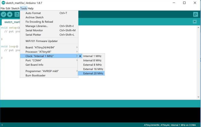
I opened Arduino software and added Attiny.
Put URL in the Additional Boards Manager URLs box: https://raw.githubusercontent.com/damellis/attiny/ide-1.6.x-boards-manager/package_damellis_attiny_index.json
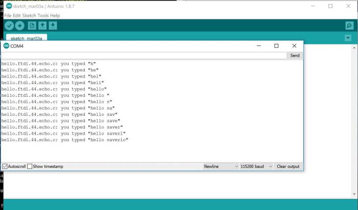
Then I have opened a system monitor and started communications with the board.
Problems
The only difficult part that I have faced was to properly design the board in Eagle. However, it was similar to a puzzle and was interesting to resolve.
Files