9. Embedded programming
DDRx - PORTx - PINx
The ports are bi-directional I/O ports with optional internal pull-ups. Each port pin consists of three register bits: DDxn, PORTxn, and PINxn.
According to 10.3 Register Description / ATtiny24A/44A/84A / 8183F–AVR–06/12, I choose ports that I used for my project:
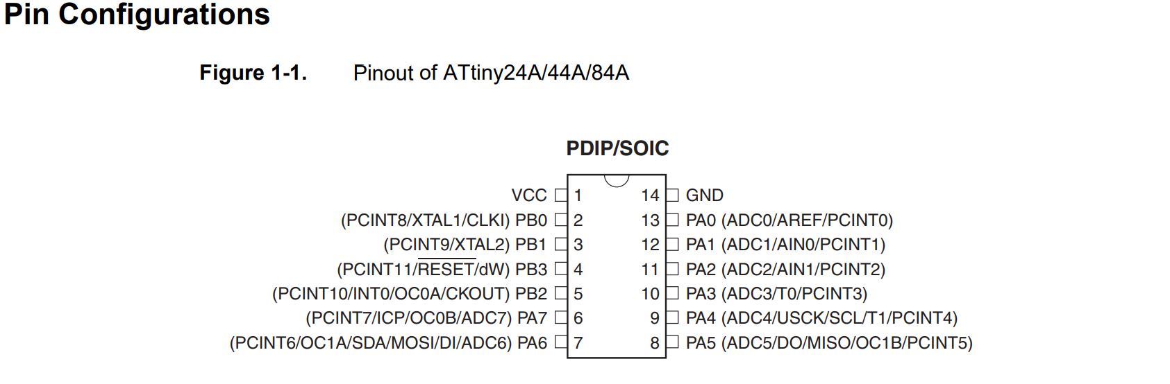
- PA7 as OUTPUT;
- PA3 as INPUT for button switch;
Otherwise, this week I’ve got some problem with 20MHz Xtal, than I’ve other 2 free pin:
- PB0 as 2nd OUTPUT;
- PB1 as 3th OUTPUT.
Note
DDRB or DDRA = DATA DIRECTION REGISTER: it means the direction of this line of data it will be OUTPUT or INPUT
PORTB or PORTA = this is the line of the output data
PINB or PINA = this is the line of the input data
and Letters A / B that associate with the DDR or Port or Pin are just as name.
C for AVR microcontroller
Setting a bit
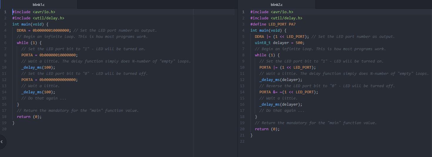
Let’s set the bit 7 to make the port pin as output. There is no direct bit set or clear instruction in ‘C’ that we can call to do this. Hence lets start with the simple binary number: 0b00000000. Now lets shift it 7 times to get 0b00000010 Now let us write that in the hex notation in a C Statement.
DDRA = DDRA | (1 << 7);
we can also concatenate the OR operation and write as:
DDRA | = (1 << 7);
Taking this a little further, you might want to define the number 7 as a constant, so that if LED is connected to some other pin, you may not want to change in all the places you’ve used it. Like so,
#define LED  7
DDRA | =  (1 << LED);
Clearing a bit
Now let us go ahead and clear the bit-7 and also assume this time that the DDRA value is 0b00000010 we need to obtain 0b00000000
Let’s write a this in ‘C’ statements:
#define LED 7
DDRA &= ~(1 << LED);
Checking a bit
Lots of times during programming, you will want check if a bit is set or clear. For example to check if the timer flag is set or let’s say in our example if the switch is pressed or released. Often this is accomplished by checking status of particular bit in a given register.
Lets say we want to check the status of 3th bit of PINA register. Then the status can be obtained by
status = (PINA & (1<<mySwitch) ! = 0);
Toggling a bit
If we need to toggle the LED connected to PORTA, bit-7 as with our example it can be accomplished by XOR operation as shown. It can be summed up as
#define LED 4
PORTA ^= (1 << LED);
My “C” Code
I’ve spent more time on assume C lenguage for AVR microcontroller and I’ve made more example to understand it.
So, you can download all my example files …
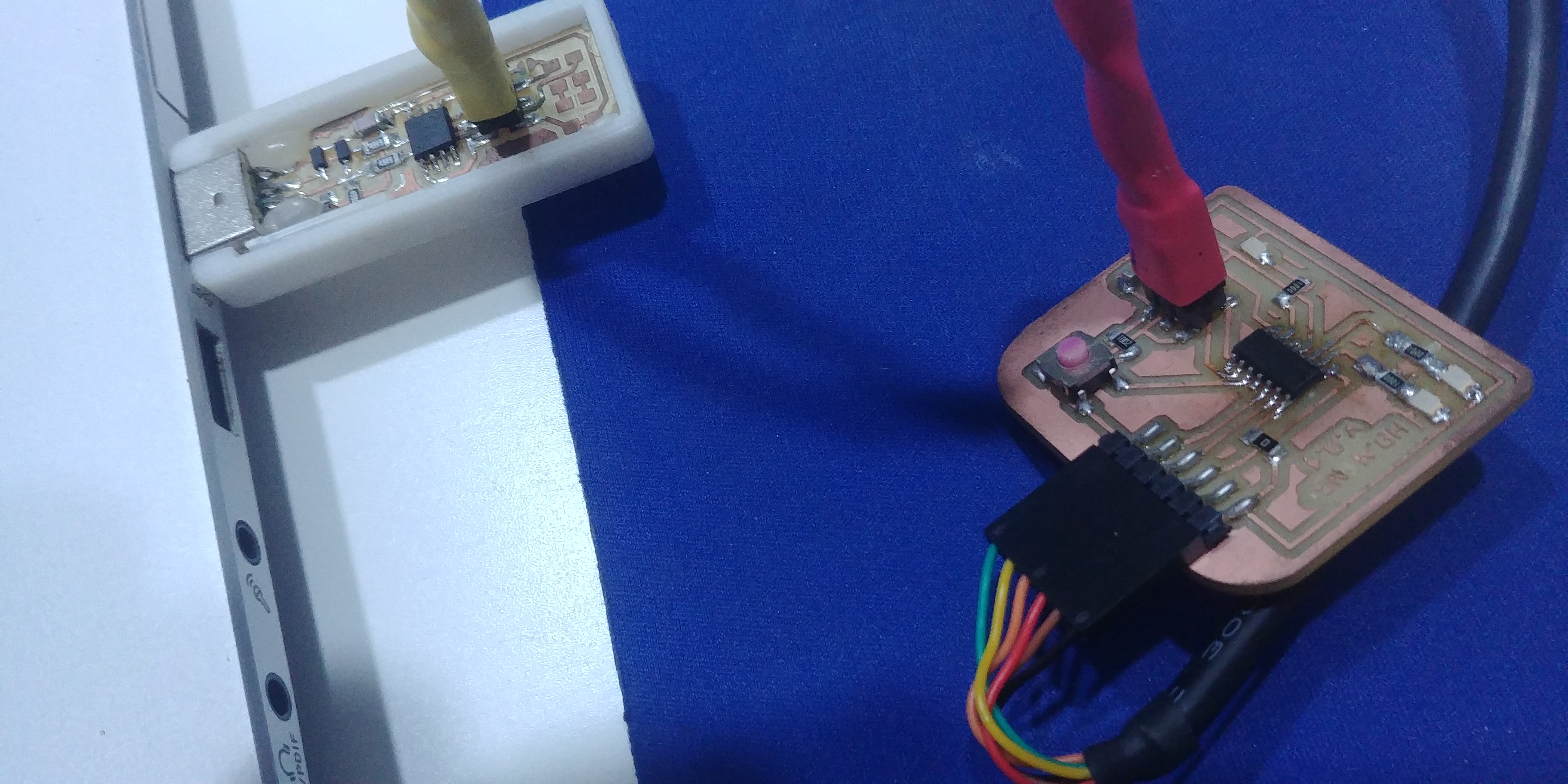
Now, this is my Hardware configuration on the board:
- 1x LED on PA7
- 1x LED on PB0
- 1x LED on PB1
- 1x Button on PA3
#include <avr/io.h>
#include <util/delay.h>
#define F_CPU 8000000
int main (void)
{
    // with OR-operation set bits numbers in DDR register, make it output
    DDRA |= (1 << PA7);
    DDRB |= (1 << PB0);
    DDRB |= (1 << PB1);

     // clear bit number 3 in DDRA register,  make it input
    DDRA &= ~(1 << PA3);

    while (1)
    {
        if (PINA & (1 << PINA3)){    // with AND-operation check if bit 3 is set
        PORTA |= (1 << PA7);
        _delay_ms(500);
        PORTB |= (1 << PB0);
        _delay_ms(500);
        PORTB |= (1 << PB1);    // with OR-operation set bit number 2 in PORTB
    } else  {
        PORTB &= ~(1 << PB1);       // else clear bit number
        _delay_ms(500);
        PORTB &= ~(1 << PB0);
        _delay_ms(500);
        PORTA &= ~(1 << PA7);

    }
}
}
Program the board trought my FabISP programmer
This is the whole log of the process; first of all I’ve set lfuse to 0XE2 to set Int. Clock @8Mhz.
ntngr@DESKTOP-SJT4DAT MINGW64 ~/FabAcademy2019/1/5_button_leds (master)
$ make
avr-gcc -mmcu=attiny44 -Wall -Os -DF_CPU=8000000 -I./ -o buttonLeds.out buttonLeds.c
avr-objcopy -O ihex buttonLeds.out buttonLeds.c.hex;\
        avr-size --mcu=attiny44 --format=avr buttonLeds.out
AVR Memory Usage
----------------
Device: attiny44

Program:     144 bytes (3.5% Full)
(.text + .data + .bootloader)

Data:          0 bytes (0.0% Full)
(.data + .bss + .noinit)


ntngr@DESKTOP-SJT4DAT MINGW64 ~/FabAcademy2019/1/5_button_leds (master)
$ ls
buttonLeds.c  buttonLeds.c.hex  buttonLeds.out  Makefile

ntngr@DESKTOP-SJT4DAT MINGW64 ~/FabAcademy2019/1/5_button_leds (master)
$ make program-usbtiny
avr-objcopy -O ihex buttonLeds.out buttonLeds.c.hex;\
        avr-size --mcu=attiny44 --format=avr buttonLeds.out
AVR Memory Usage
----------------
Device: attiny44

Program:     144 bytes (3.5% Full)
(.text + .data + .bootloader)

Data:          0 bytes (0.0% Full)
(.data + .bss + .noinit)


avrdude -p t44 -P usb -c usbtiny -U flash:w:buttonLeds.c.hex

avrdude: AVR device initialized and ready to accept instructions

Reading | ################################################## | 100% 0.01s

avrdude: Device signature = 0x1e9207
avrdude: NOTE: FLASH memory has been specified, an erase cycle will be performed
         To disable this feature, specify the -D option.
avrdude: erasing chip
avrdude: reading input file "buttonLeds.c.hex"
avrdude: input file buttonLeds.c.hex auto detected as Intel Hex
avrdude: writing flash (144 bytes):

Writing | ################################################## | 100% 0.26s

avrdude: 144 bytes of flash written
avrdude: verifying flash memory against buttonLeds.c.hex:
avrdude: load data flash data from input file buttonLeds.c.hex:
avrdude: input file buttonLeds.c.hex auto detected as Intel Hex
avrdude: input file buttonLeds.c.hex contains 144 bytes
avrdude: reading on-chip flash data:

Reading | ################################################## | 100% 0.13s

avrdude: verifying ...
avrdude: 144 bytes of flash verified

avrdude done.  Thank you.


ntngr@DESKTOP-SJT4DAT MINGW64 ~/FabAcademy2019/1/5_button_leds (master)
$
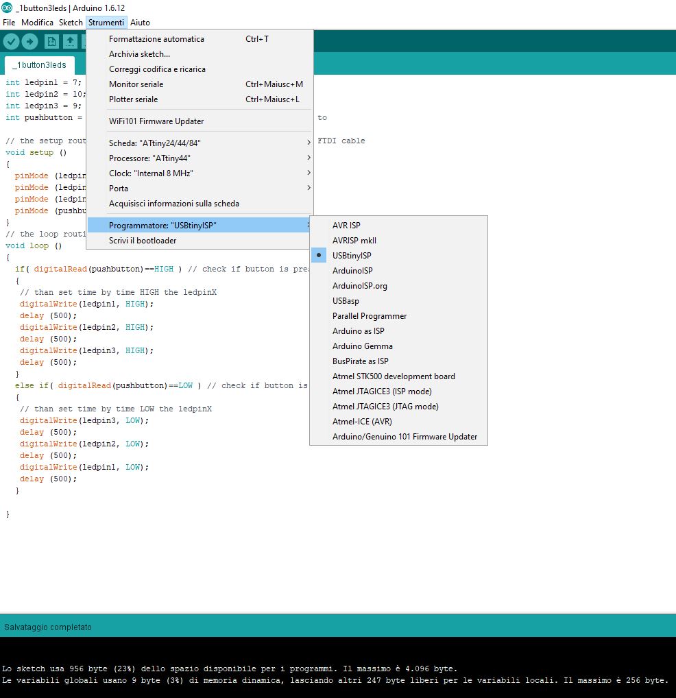
My “Arduino” Code
I’ve made the same example above, but I wrote it in Arduino IDE.
This is my code:
int ledpin1 = 7;         // the PWM pin the LED is attached to
int ledpin2 = 10;
int ledpin3 = 9;
int pushbutton = 3;     // the Analog pin the Button is attached to

// the setup routine runs once when you supply the board trought FTDI cable
void setup ()
{
  pinMode (ledpin1,OUTPUT);    // declare pin 7 to be an output
  pinMode (ledpin2,OUTPUT);    // declare pin 7 to be an output
  pinMode (ledpin3,OUTPUT);    // declare pin 7 to be an output
  pinMode (pushbutton,INPUT); // declare pin 3 to be an input
}
// the loop routine runs over and over again forever
void loop ()
{
  if( digitalRead(pushbutton)==HIGH ) // check if button is pressed
  {
   // than set time by time HIGH the ledpinX
   digitalWrite(ledpin1, HIGH);
   delay (500);
   digitalWrite(ledpin2, HIGH);
   delay (500);
   digitalWrite(ledpin3, HIGH);
   delay (500);
  }
  else if( digitalRead(pushbutton)==LOW ) // check if button is pressed
  {
   // than set time by time LOW the ledpinX
   digitalWrite(ledpin3, LOW);
   delay (500);
   digitalWrite(ledpin2, LOW);
   delay (500);
   digitalWrite(ledpin1, LOW);
   delay (500);
  }

}
Note
Using two different kind of code I can verify that, with same functions:
- Compiled in C code is 144 bytes of flash written;
- Compiled Arduino code is 956 bytes of flash written.
Test another architecture
To complete my assignment I’ve used Raspberry Pi ZeroW coding a Blinking LED through Python and python-rpi.gpio.
Raspbian Stretch
I assume that you have installed a Raspbian Stretch image on an SD card from your PC. Well, don’t remove the SD card from your computer and open the /boot directory and follow these simple steps to enable WiFi connection and SSH:
- in the root you must create an empty file called
SSH - create a file in this directory called wpa_supplicant.conf.
The file should contain the following details:
country=US # Your 2-digit country code
ctrl_interface=DIR=/var/run/wpa_supplicant GROUP=netdev
network={
    ssid="YOUR_NETWORK_NAME"
    psk="YOUR_PASSWORD"
    key_mgmt=WPA-PSK
}
- The next step is to put the micro SD card into the Pi, boot, and then try to connect via WiFi.
At this point you are connected to WiFi network and ready to enstablish an SSH connection via PuTTY software.
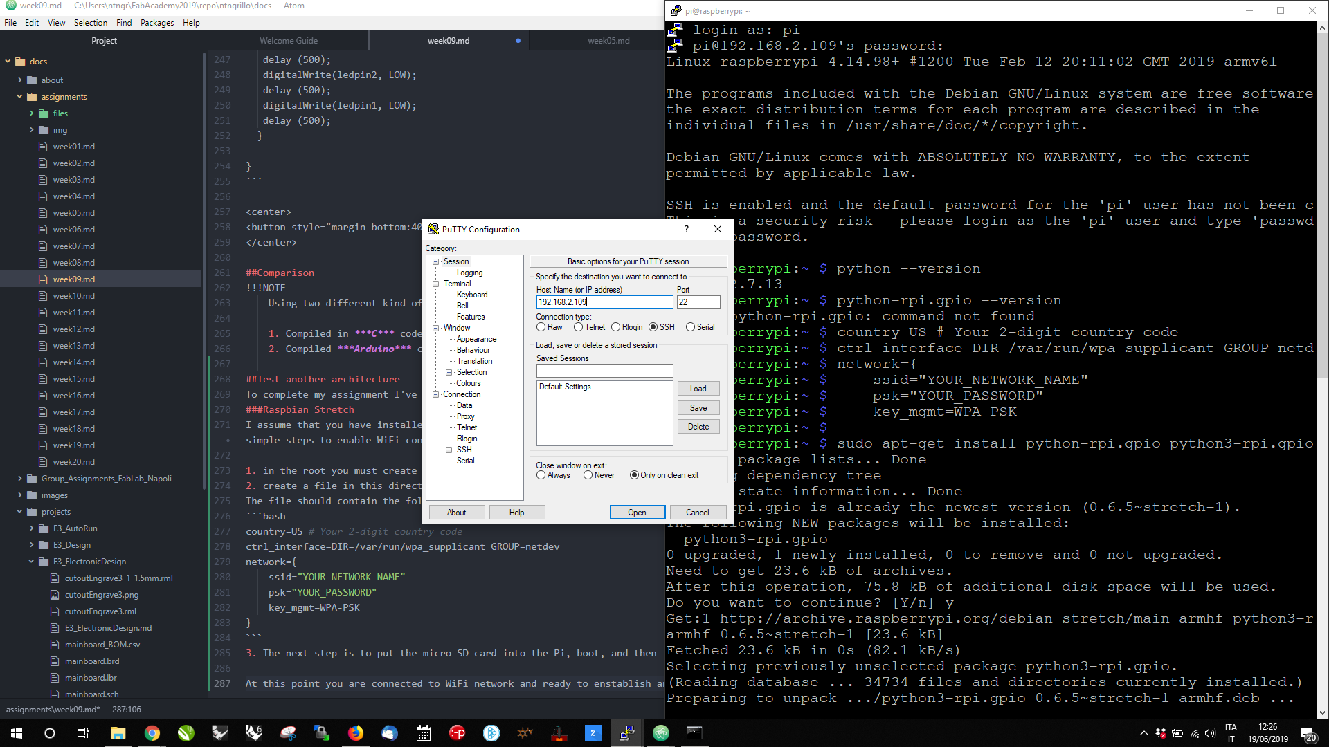
login as: pi
pi@192.168.2.109's password:
Linux raspberrypi 4.14.98+ #1200 Tue Feb 12 20:11:02 GMT 2019 armv6l

The programs included with the Debian GNU/Linux system are free software
the exact distribution terms for each program are described in the
individual files in /usr/share/doc/*/copyright.

Debian GNU/Linux comes with ABSOLUTELY NO WARRANTY, to the extent
permitted by applicable law.

SSH is enabled and the default password for the 'pi' user has not been c
This is a security risk - please login as the 'pi' user and type 'passwd a new password.
Python and GPIO
once connected verify your Python version than install python-rpi.gpio as follows:
pi@raspberrypi:~ $ python --version
Python 2.7.13
pi@raspberrypi:~ $ sudo apt-get install python-rpi.gpio python3-rpi.gpio
Reading package lists... Done
Building dependency tree
Reading state information... Done
python-rpi.gpio is already the newest version (0.6.5~stretch-1).
The following NEW packages will be installed:
  python3-rpi.gpio
0 upgraded, 1 newly installed, 0 to remove and 0 not upgraded.
Need to get 23.6 kB of archives.
After this operation, 75.8 kB of additional disk space will be used.
Do you want to continue? [Y/n] y
Get:1 http://archive.raspberrypi.org/debian stretch/main armhf python3-rarmhf 0.6.5~stretch-1 [23.6 kB]
Fetched 23.6 kB in 0s (82.1 kB/s)
Selecting previously unselected package python3-rpi.gpio.
(Reading database ... 34734 files and directories currently installed.)
Preparing to unpack .../python3-rpi.gpio_0.6.5~stretch-1_armhf.deb ...
Unpacking python3-rpi.gpio (0.6.5~stretch-1) ...
Setting up python3-rpi.gpio (0.6.5~stretch-1) ...
pi@raspberrypi:~ $
Blink Led in py
Now I’ve created a file in the user pi directory called blinkingLED.py.
pi@raspberrypi:~ $ sudo nano blinkingLED.py
import RPi.GPIO as GPIO # Import Raspberry Pi GPIO library
from time import sleep # Import the sleep function from the time module

GPIO.setwarnings(False) # Ignore warning for now
GPIO.setmode(GPIO.BOARD) # Use physical pin numbering
GPIO.setup(8, GPIO.OUT, initial=GPIO.LOW) # Set pin 8 to be an output pin and set initial value to low (off)

while True: # Run forever
    GPIO.output(8, GPIO.HIGH) # Turn on
    sleep(1) # Sleep for 1 second
        GPIO.output(8, GPIO.LOW) # Turn off
        sleep(1) # Sleep for 1 second
Save and Exit from nano, if you used it.
Now you can test your code but remember to:
- Connect the anode of the LED to the pin 8
- Connect the cathode of the LED to the GND pin.
- RUN the code as mentioned below:
pi@raspberrypi:~ $ sudo python blinkingLED.py
DOWNLOAD THE PYTHON CODE