7. Electronics design
Design my Hello Board!
In order to redraw the echo hello-world board adding a button switch and a LED, I started from my old Hello Board redesigned some times ago and based on Neil’s echo board from Here.
First of all, check the necessary components:
Components
- Attiny44
- 1x Capacitor 1uF
- 1x Resistor 10KΩ
- 1x 3pads Resonator //But I use a 20MHz 2pads Xtal with 2x 18pF Capacitor on GND
- 1x 2x3 ISP connector
- 1x 6P FTDI connector
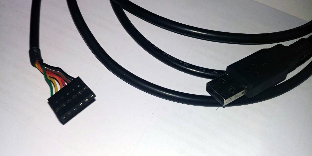
- 1x 3.3v FTDI cable
to add extra components to this recipe, I need:
- 1x green LED
- 1x Resistor 100Ω //figured that current that it needs to be fully bright is 3.3v and 20ma. Applying Ohm’s law to this values you get 165 Ohm; better than 499 Ohm
- 1x Switch button
- 1x 10KΩ Resistor //as PULLDOWN resistor for the button
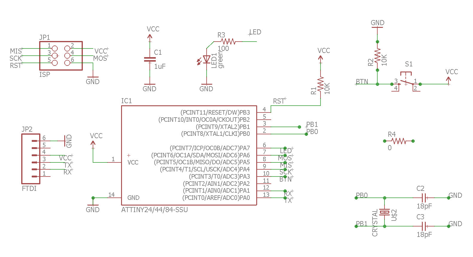
Schematic
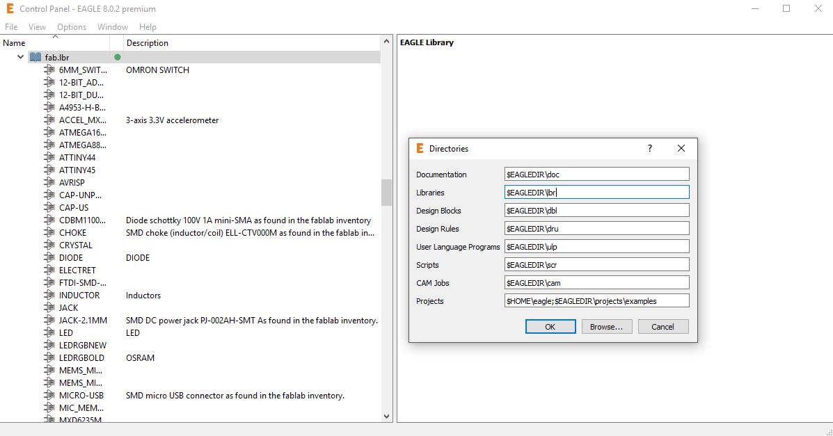
At this point I choose Eagle as Electronics design software tool to write my Scheme and design my Board.
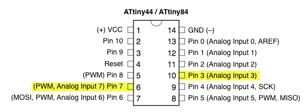
According to ATtiny44-84 datasheet I’ve choose to use PIN7 as PWM for LED and PIN3 as Analog Input for Button.
the workflow is simple following this steps:
-
Import all the necessary library to find components I need in the board;
-
Create new .SCH (scheme) file;
- from Edit/Add…
 all the components I need in the scheme canvas and remember to give they a $VALUE
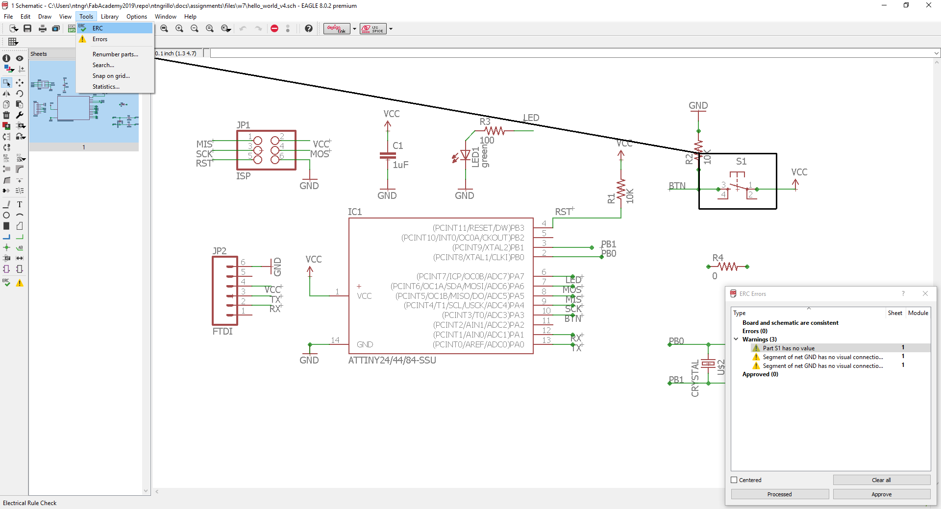
- use $NAME
 to create connections;
 -
remember to use the aided tool as ERC to check and underline Warnings and Errors
-
now I can Generate the board —> File/
Board
Once generated the .BRD file, you must design your physical board with all components on it; follow me:
-
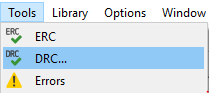
If you have completed Week5 assignment, you have generate during that week the design rules of your pcb milling production process; well, now you can apply all that you learned, setting that rules trough by DRC tool;
-
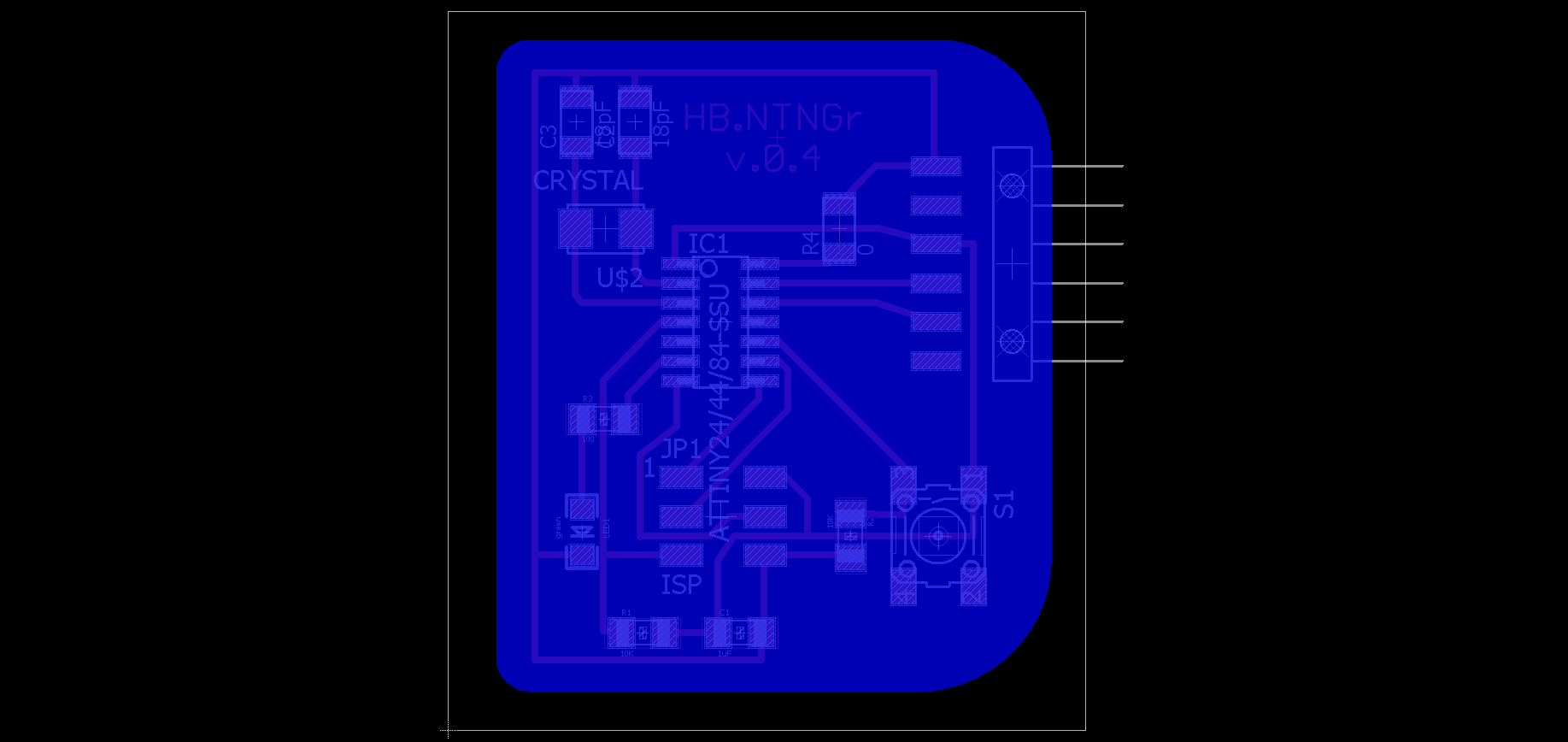
OK, once you set View/
 the Top layer and consider that you need another two layers, dimensions and cutout, you are ready to place the components on your board;
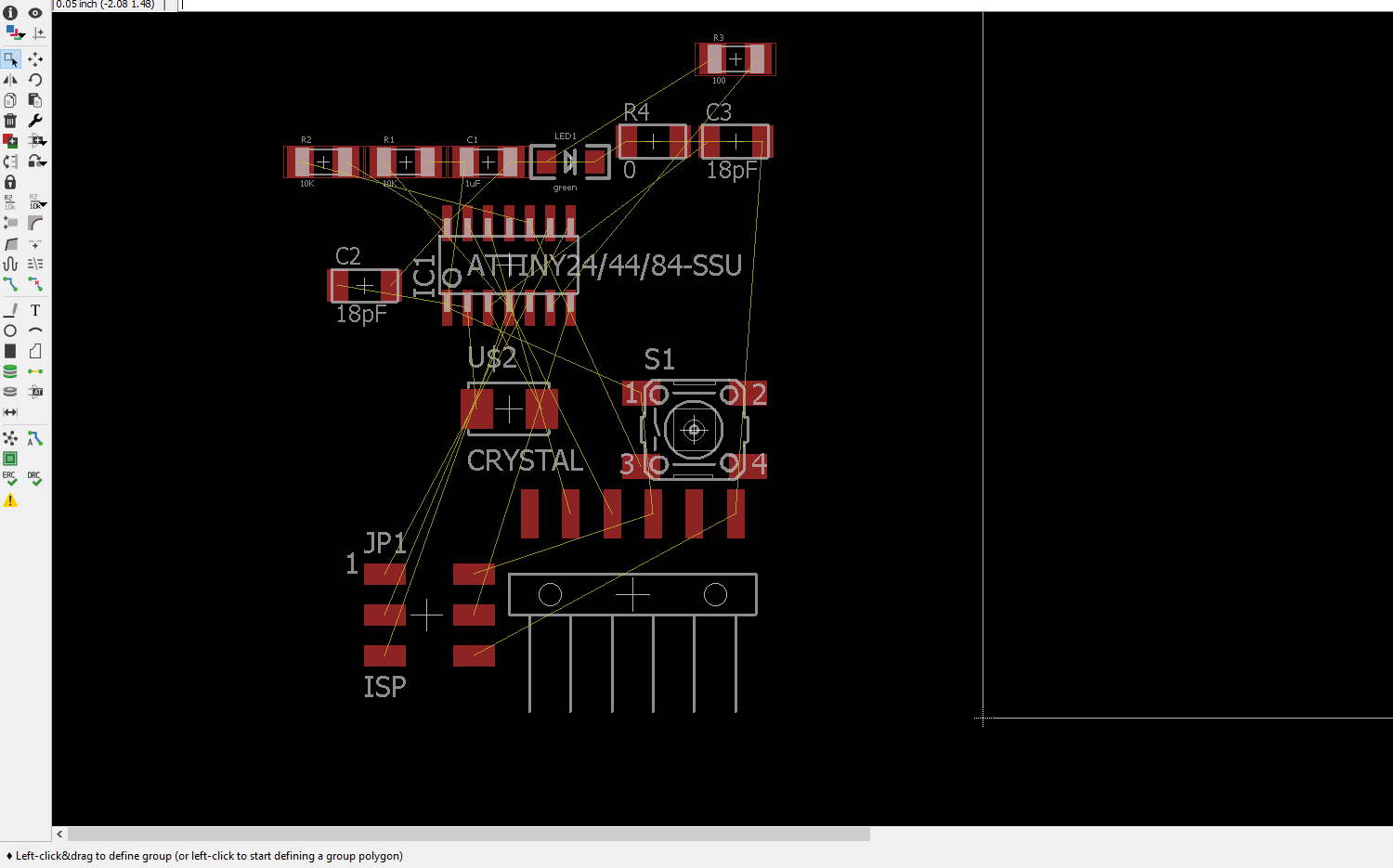 the yellow lines that represents the right connections, helps you to trace the routes manually
  , remove them
  and/or if you want, you can try to use autoroute command to find the right traces (not so easy!!!)
 -
Remember that Tools/
 is your best friend to reset your connections (yellow lines) once you remove the wrong traces.
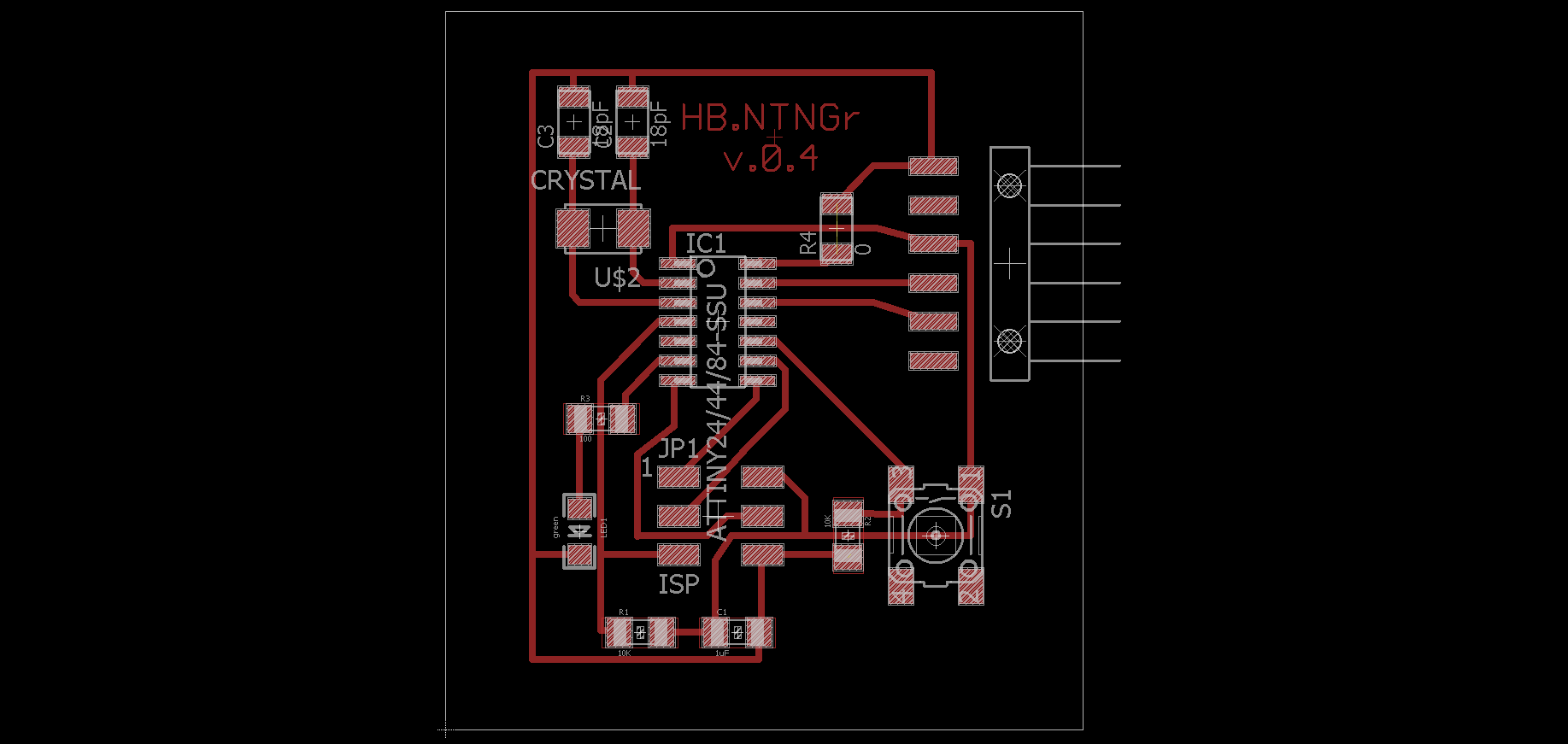
-
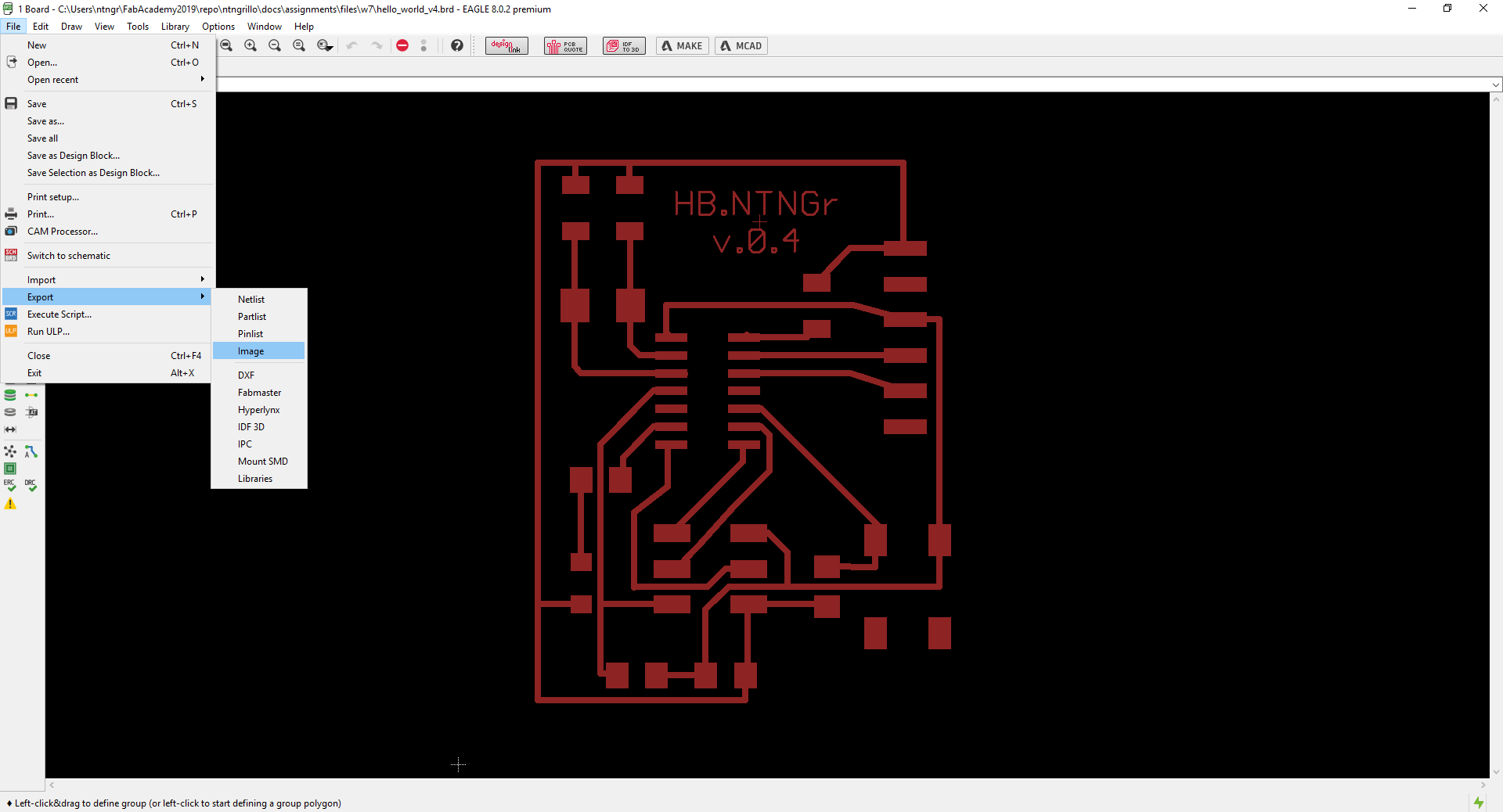
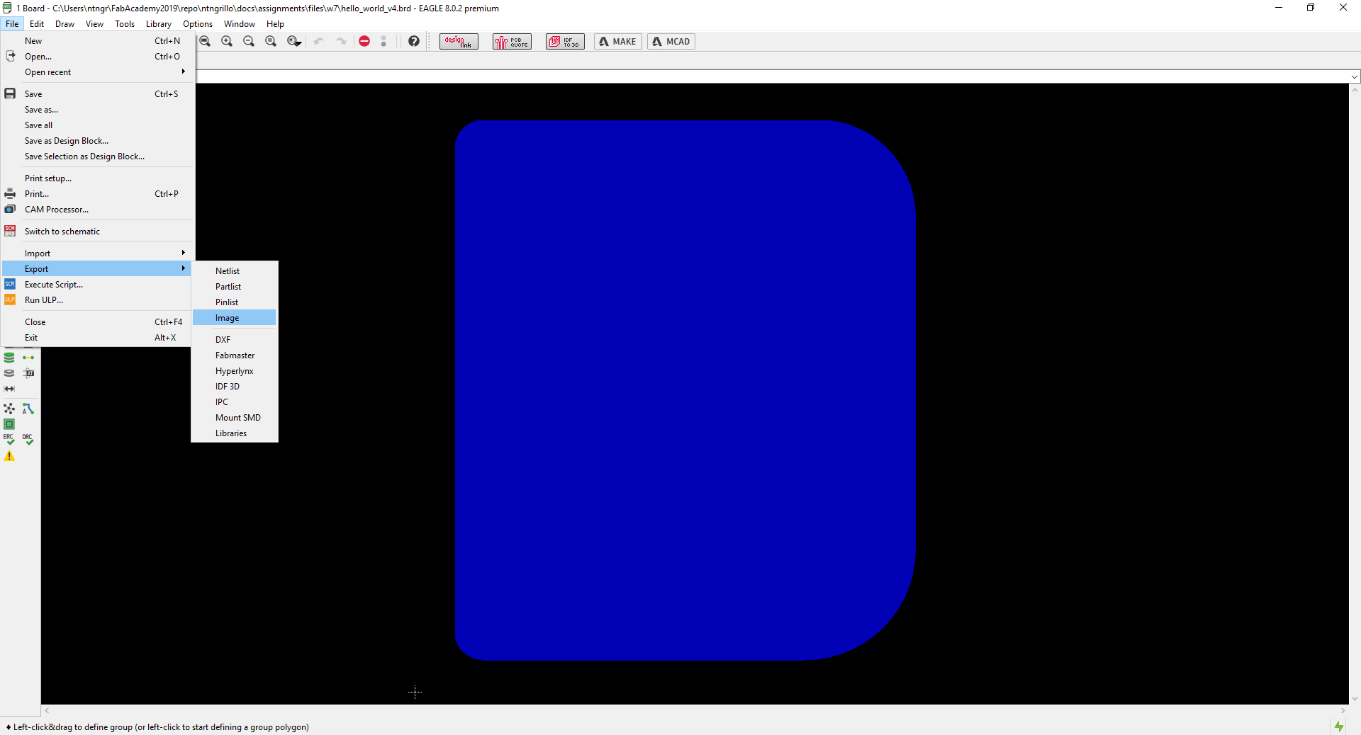
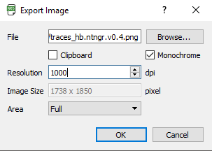
well, now you can export traces and cutout 1000dpi PNG file, respectively by their layer.
-
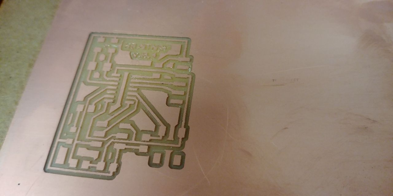
As in Week5 product your board…
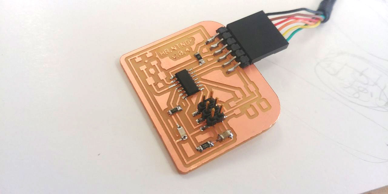
Assembling and Programming
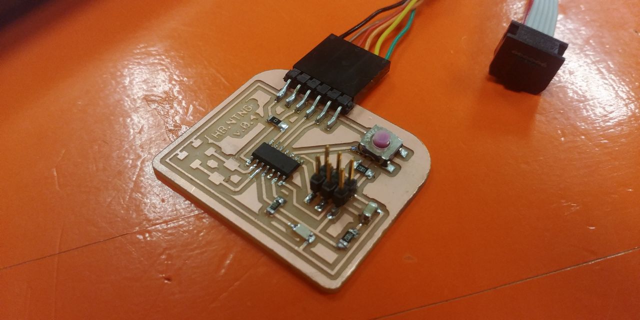
After preparing my board, I mount on it only:
- Attiny44
- 0 Ohm res
- 100 Ohm res
- 10K Ohm res
- 1 uF cap
- FTDI header
- ISP header
 and test it as follow …
- connect the board to the 3.3v FTDI cable
- connect the FabISP to a USB PC port
- connect the board and programmer trough by ISP cable pay attention to the right addressing of the MISO
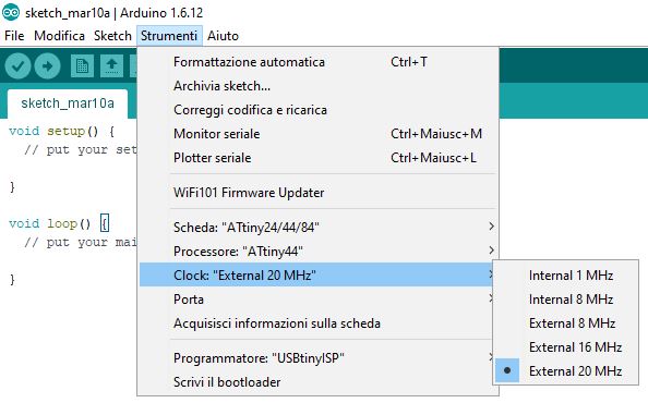
- on the Arduino IDE (check that the version you use is the 1.6.12) set parameters as follow
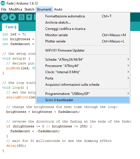
- Burn Bootloader
- open an example from arduino sketches. I choose Fade, and obviously change the pin number where LED is attached to AVR
- now upload the program trough by your programmer, holding shift on the keyboard.
Well, at this point I’ve add a button and a 10KΩ pulldown resistor.
Trough by Arduino IDE I’ve reprogrammed my board as follow:
int ledpin = 7;         // the PWM pin the LED is attached to
int pushbutton = 3;     // the Analog pin the Button is attached to

int brightness = 0;     // how bright the LED is
int fadeamount = 1;     // how many points to fade the LED by

// the setup routine runs once when you supply the board trough FTDI cable
void setup ()
{
  pinMode (ledpin,OUTPUT);    // declare pin 7 to be an output
  pinMode (pushbutton,INPUT); // declare pin 3 to be an input
}
// the loop routine runs over and over again forever
void loop ()
{
  if( digitalRead(pushbutton)==HIGH && brightness<255 )
  {
    // fade in led
    brightness = brightness + fadeamount;// increase brightness
    if( brightness>255 ) // check that brightness doesn't exceed 255
      brightness = 255;
    analogWrite(ledpin,brightness);
    delay (1);
  }
  else if( digitalRead(pushbutton)==LOW && brightness>0 )
  {
    // fade out led
    brightness = brightness - fadeamount;// decrease brightness
    if( brightness<0 )// check that brightness doesn't go below 0
      brightness = 0;
    analogWrite(ledpin,brightness);
    delay (1);
  }

}
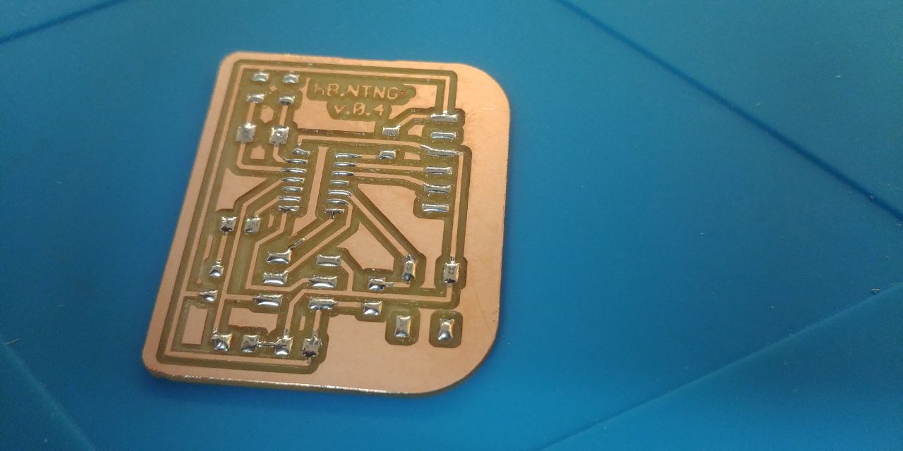
Update board with Xtal
After some week, and remaking more times the board, I’ve solved the mistake …
After add on the board the 20MHz Xtal, due to a logistics error, I though I was soldering the 22pF capacitors on the board, but by mistake I took the 0.1uF capacitors. After I noticed it and soldered the capacitors of the right value, everything went well, as follows:
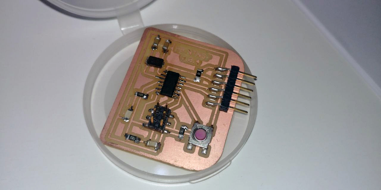
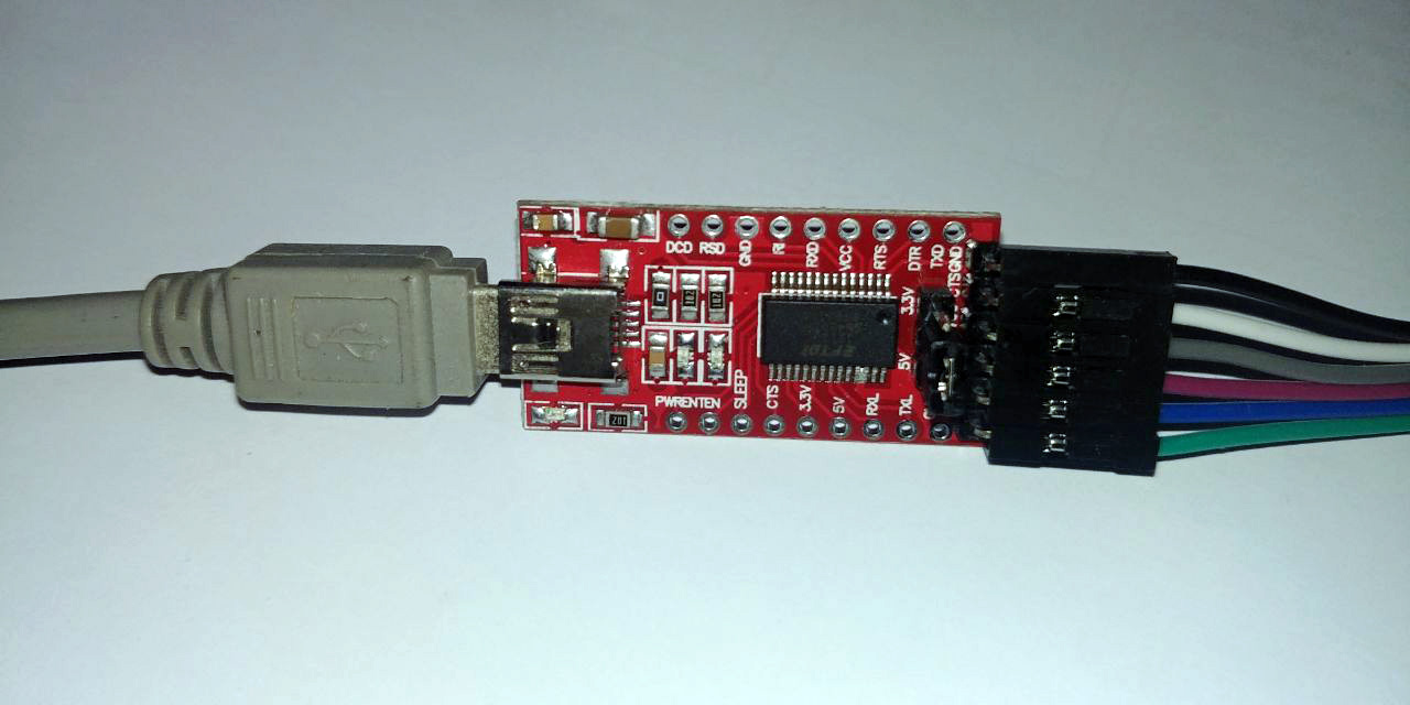
Up to this moment I powered my board with a 3.3v ftdi cable,
but having to run the board with the 20MHz crystal, I powered the board through a 5v ftdi232 adapter.
Burn Bootloader using these parameters.
Operation of a Microcontroller circuit board
I’ve tested the operation of a ATmega328P microcontroller board, output device board, with “MT8205” multimeter/oscilloscope 2in1 tool.
CONTINUITY TEST
One of the commom and useful thing you want to do when building a circuit is to check the CONTINUITY of your components.
The continuity test serves to check the presence of a current flow between points.
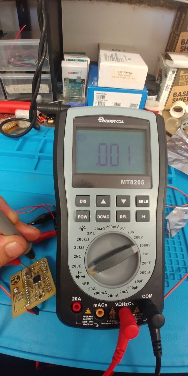
To test it set the multimeter to “continuity”, looks like an icon as follows:
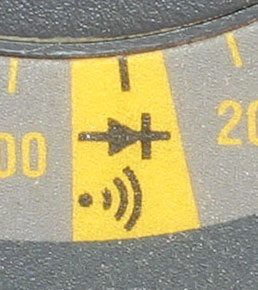
Test the probes by touching them together, they should emmit a bip! Using the probes touch different separate pins. If you hear a tone it means they are connected.
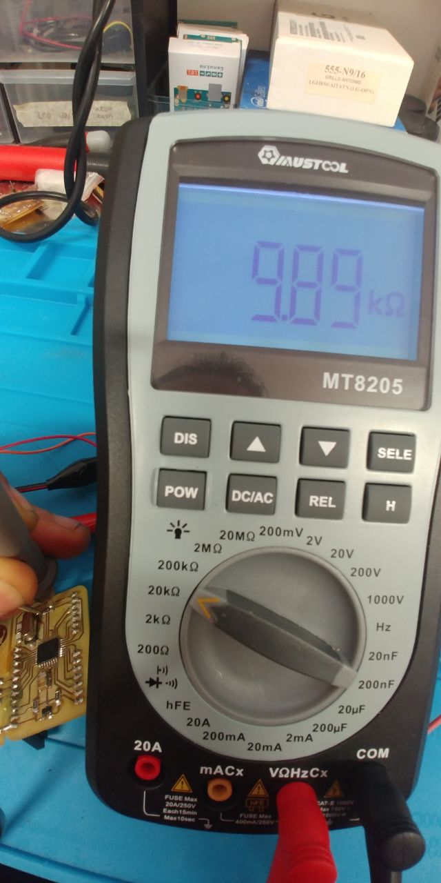
RESISTORS TEST
Select the right scale in Ohm to test the value of the resistor you are use in your circuit board.
Using the probes touch the two sides of the resistor and read the correct value:
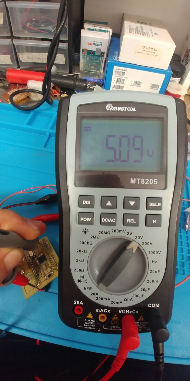
VOLTAGE TEST
Find the correct Voltage you are using to supply your board using the probes touch respectively the Vin and GND, but remember to set the right scale and set the multimeter to read DC current. In my case I’ve set the scale on 20V to read the 5V I need:
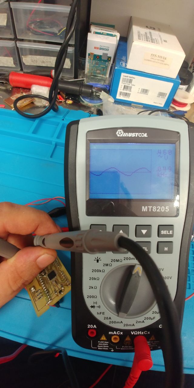
XTAL FREQUENCY TEST
I’ve used a second functionality of my “MT8205” to test the frequency of the 16MHz crystal I use to assemble my board.