Week4 Group Assignment: Computer controlled cutting
Characterizing the machine - Laser cutter
Setup and Test
Make lasercutter test part(s), varying cutting settings and slot dimensions.
HARDWARE
Setup
- Tool: Laser Cutter CO2
- Class: 3R (for this class, lasers are considered safe when handled carefully. There is only a small hazard potential for accidental exposure. For visible-light lasers, Class 3R lasers’ output power is between 1 and 4.99 milliwatts.
- Model: Epilog Helix 24” x 18” (609.6mm x 457.2mm) 45W
- Materials: Plywood 4mm; Cardboard 6mm
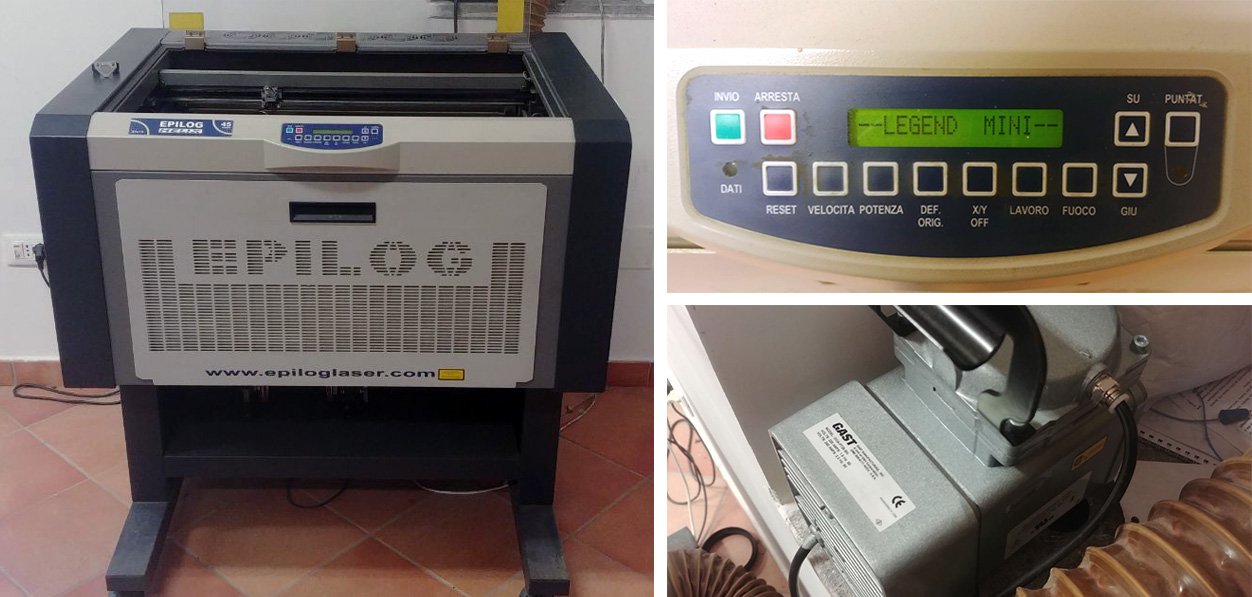
Once we have switch ON our lasercutter system (Epilog Laser, Air Assist, Filter System), we have make some operation to set User origin and Focus 2" lens on the piece of cardboard. I’ve resumed the steps on the following Gif.
- Switch ON the laser
- Switch ON the pointer
- Unlock X/Y motor axes
- helping you with the pointer, move the X/Y axes to set the user origin, in the upper left corner of the piece to cut, then SET with Origin Button
- turn ON the Focus Mode and helping yourself with the spacer tool, move the Z axis through the UP and DOWN buttons, until the spacer touches the surface of the piece to be cut
SOFTWARE
EPILOG DASHBOARD VS VISICUT
We usually use “Epilog Dashboard” driver to manage and send a job to the our Epilog mini 24”.
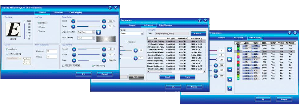 The driver can set parameters like power, speed and frequency per color or for the whole job, but only lines thinner than a dpi-dependent threshold are recognized to be cut. Everything else will be dithered by the selected algo- Parameters for certain materials can be saved to a file rithm (Standard, Brighten, LowRes, Floyd Steinberg, Jarvis and Stucki) and added to the engraving part. The settings can also be saved to a file, which allows the creation of a database for often used materials. The driver also supports a 3D-engraving mode, where the grey value of every pixel is translated into laser power, allowing different engraving depths and 3D effects.
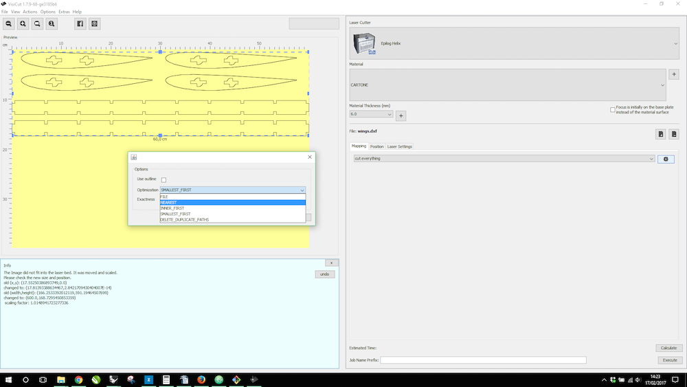 Another software that we use without installing Epilog drivers is VisiCut. It permits us to manage data and parameters trought a usefull interface that can show the vector and bitmap imported files on the stage, representing the working area of the our Epilog Laser. Using VisiCut you can use any line thikness for the vector curves and then assign to the line the right operation Mapping you want, such as Cut everything, Mark and/or Engrave.
Once you have calculate a Job, you can send it trought by WiFi Network; when the Lasercutter recive the code, it show you a Job text message:
Another software that we use without installing Epilog drivers is VisiCut. It permits us to manage data and parameters trought a usefull interface that can show the vector and bitmap imported files on the stage, representing the working area of the our Epilog Laser. Using VisiCut you can use any line thikness for the vector curves and then assign to the line the right operation Mapping you want, such as Cut everything, Mark and/or Engrave.
Once you have calculate a Job, you can send it trought by WiFi Network; when the Lasercutter recive the code, it show you a Job text message:
Advice
Job was sent as ‘$jobname’
Please:
-
Close the lid
-
Turn on the Ventilation and Air Assist
-
And press ‘Start’ on the Lasercutter $name
I think essential to use a nesting software to optimize the waste material. Nesting software is very expensive, but there is some Opensource alternative.
I always optimize the material I use, and when I don’t make this manually I use Deepnest.io
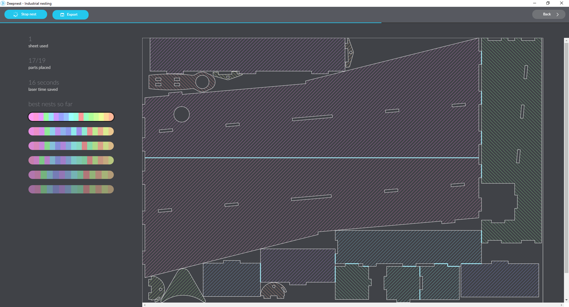
Simply as say Hello
- Import .SVG or .DXF file of the single or spare parts you want nesting. The software recognize the single closed area and divide the shapes in a list.
- Edit quantity for each pice in the list (if you want duplicate more than 1).
- Draw a rectangular shape and flag it as sheet
- Start Nesting (during this operation the software delete automatically double lines and optimize the shapes on the sheet or sheets; you can Export the best result anytime)
Power/Speed/Freq.
At First we did several tests, starting from the standard values suggested by the epilog manual to cut matboard (no thickness specified), setting the following parameters:
Suggested Parameters from Epilog Helix Manual Guide
- Power: 40%
- Speed: 30%
- Frequency: 500Hz
As I saw we did more tests from this starting point…
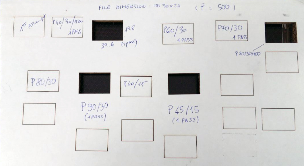
so we have compared the values with each other, considering both the cutting precision measured by the dimensions of the final piece, and the possible steps to make the cut:
| Power (%) | Speed (%) | Frequency (Hz) | Pass | Cut | Final Dimensions (mm) |
|---|---|---|---|---|---|
| 40 | 30 | 500 | 1 | NO | none |
| 40 | 30 | 500 | 2 | YES | 29.6 X 19.8 |
| 60 | 30 | 500 | 1 | NO | none |
| 70 | 30 | 500 | 1 | NO | none |
| 80 | 30 | 500 | 1 | NO | none |
| 80 | 30 | 100 | 1 | YES | 29.7 X 19.8 |
| 90 | 30 | 500 | 1 | YES | 29.6 X 19.7 |
| 45 | 15 | 500 | 1 | YES | 29.8 X 19.8 |
Finding “kerf”
Kerf is determined by material properties and thickness, the focal length of the lens and the gas used while cutting.
4mm Plywood
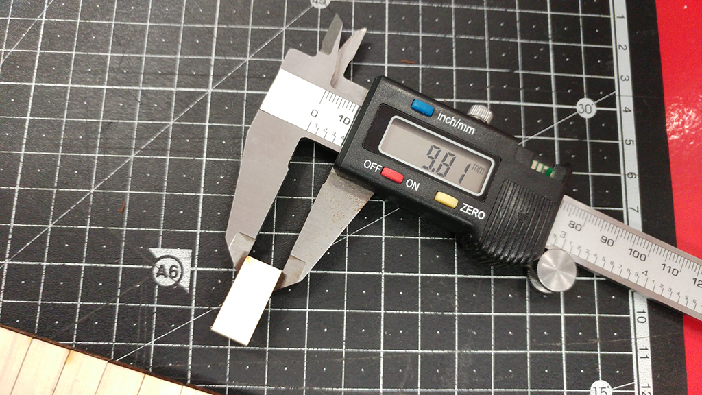
First of all I’ve designed a simple test in order to find a kerf. As in the follow picture we have drawn 9 rectangular pieces (10mm each) for 10 vertical cuts. This for make an average on the long distance.
Tip
Remember to delete all the double lines from the sketch.
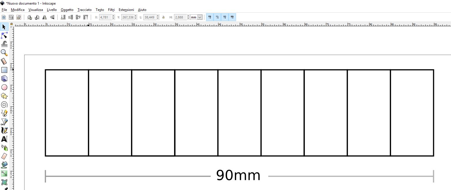
After cutting the 9 rectangles, pushed together at one end of the “frame”, the resulting gap at the other end is the sum of the kerfs.
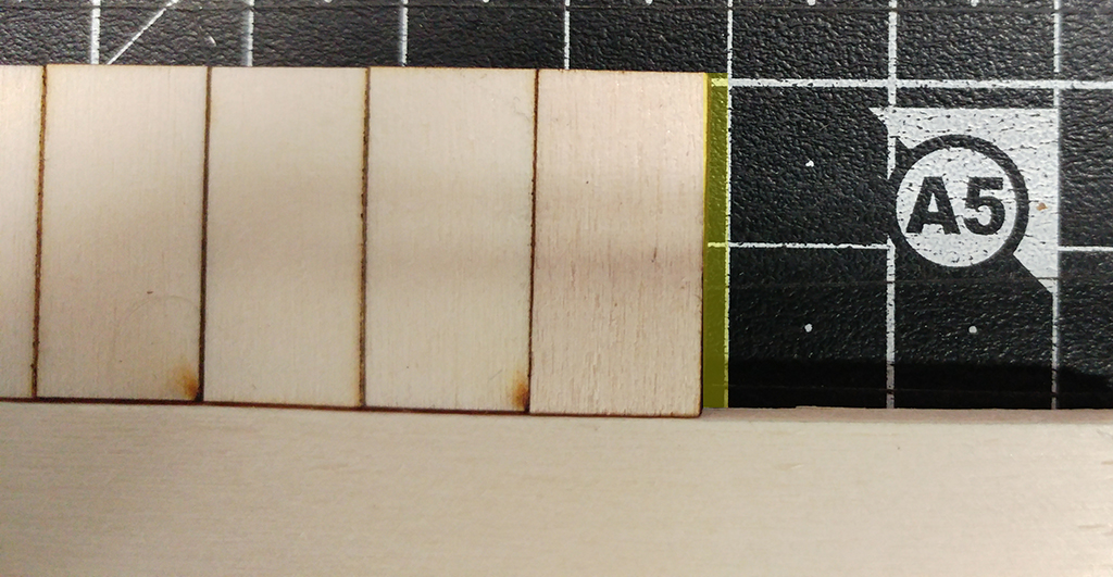
Dividing this gap by ten gives the average kerf for that material and material thickness.
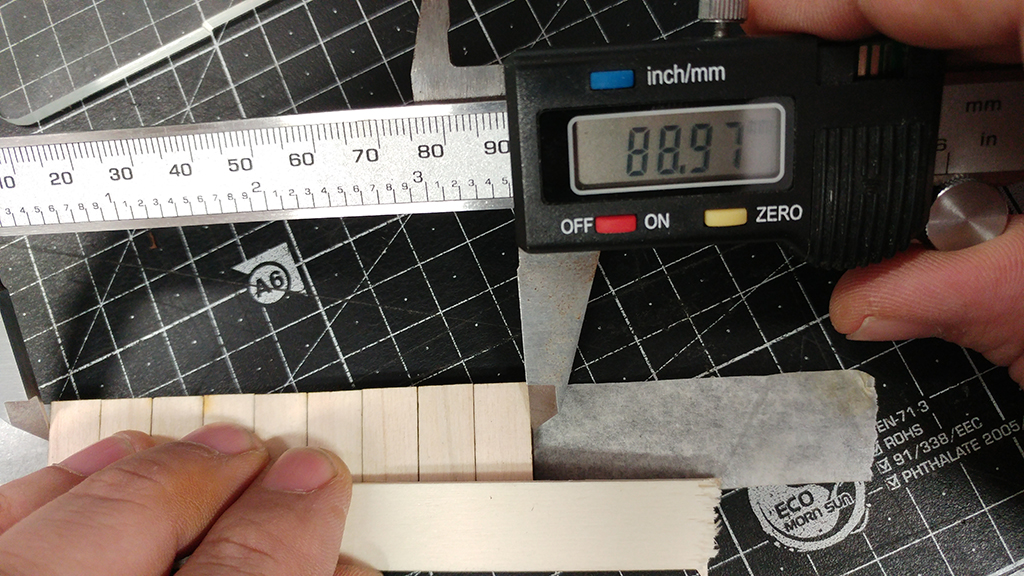
In the our case we’ve obtained a 0.1mm kerf for plywood with 4mm thickness.
6mm Cardboard
We did the previous test looking for the kerf for 6mm cardboard, this time creating 5 small rectangles and dividing the delta for 6 lines …
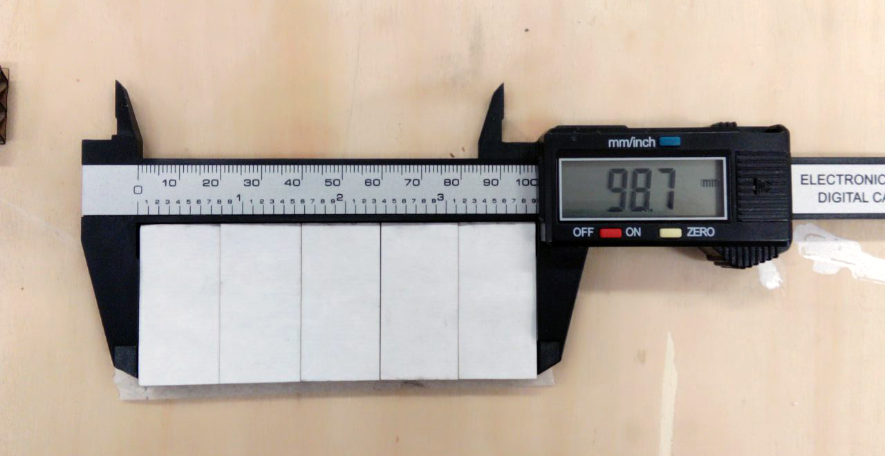
finally we have cardboard kerf in: 0.217 mm