"Our technologies have outpaced our ability, as a society, to understand them. Now we need to catch up." - Joi Ito
Computer Controlled Cutting
This week I had to design a parametric press-fit kit, lasercut it and so something with the vinyl cutter machine. Unfortunely the laser cut machine in the Fab Lab Yucatán, where I work and I'm doing the Fab Academy provisionally until I get my visa to travel to Madrid to follow it on Fab Lab IED Madrid, wasn't working as it didn't have a power supply. So I had to attend Fab Lab IYEM, the recent open initiative of the city hall.
Inspirations && Aspirations
Nervous System - Awesome functional parametric design of anything you imagine, from puzzles to jewelry.
Nintendo Labo - Great cardboard product design.
Designing in Fusion 360
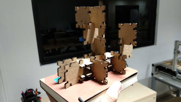
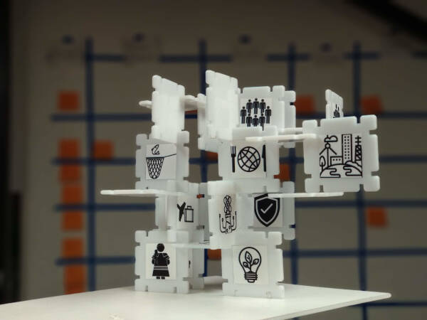
I have used Fusion 360 for some years now, but I have never used the parametric functions from it. By reading this article I got inspired to try to make something parametric to cut on the laser cutter. My first design is a kit of blocks called FabStory, where kids can build structures for storytelling. For this I used 3mm MDF.
Tip: I used a lot the Mirror tool, so I created a shortcut for it as Fusion 360 doesn't have a default one. To do this, just go to SKETCH > Mirror and select the 3 dots option on the right side of the tool and select "Change Keyboard Shortcut". Select the shortcut you want to implement, I used "Shift+m".
This are the steps I followed to design the blocks:
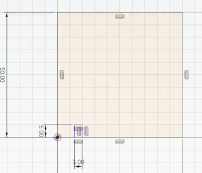
- 1. Create a sketch and then create a rectangle.
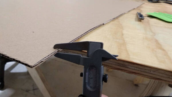
- 2. Create a slot in the lower side of the rectangle. The width of the slot is 3mm, as I am using this thickness in the material. Because of the laser's kerf, the assembly is probably gonna be loose, so I'll cut pieces with different widths.
- 3. Create a vertical line in the middle of the rectangle, this is going to be my line reference to copy the slots.
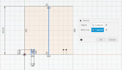
- 4. Select the mirror option, this is going to copy our slot, keeping parameters so if we change the first slot, the second one will reflect the changes. So go to Sketch > Mirror.
- 5. The mirror window will pop up. If not, It should be hiding on the right side of the screen. With the Objects option, select the objects you'll want to mirror, in this case the slot. With the Mirror Plane option, select the line of reference.
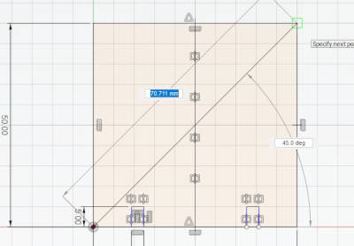
- 6. Create a diagonal line and mirror, following the previous steps, the two slots now created.
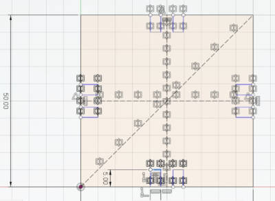
- 7. Create an horizontal line in the middle of the rectangle and mirror the lower slots.
- 8. Using the already created vertical line, mirror the slots on the left.
Now you can change the width and height of the original slot and the other ones will change. Also you can move the slot by clicking in it andd dragging, and again, the other ones will follow.
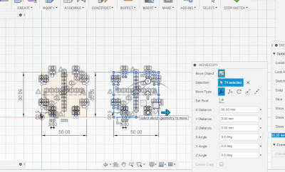
To lasercut this design I exported the .dxf file, by right-clicking the Sketch I'm working in and selecting the Save As DXF option.
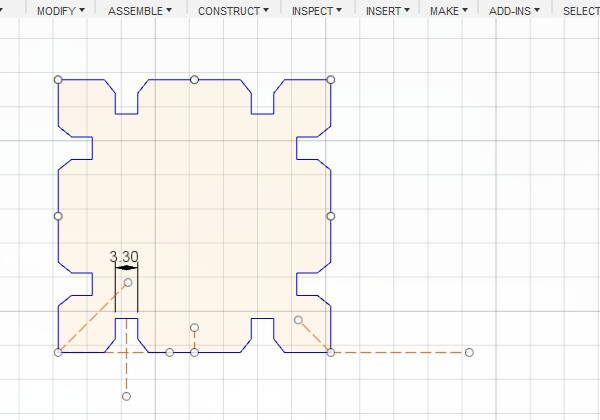
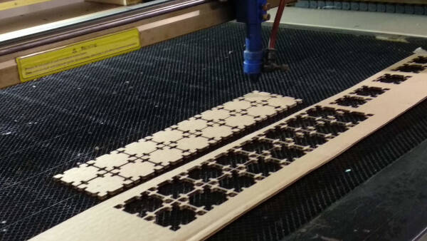
Update: On the Globa Review my guru, Nuria Robles, and my instructor, Marta Verde, told me that using a chamfer on the slots of my design will improve the joint of the pieces, so I took the chance to improve the workflow of the parametric design of the blocks.
So this are the steps I followed now:
- 1. Create the lines with any dimension you want. Later I'll define it.
- 2. Create a construction line in the middle of the slot. To create the construction line just create a regular line, select it and on the SKETCH PALETTE on the right select the Construction option.
- 3. Mirror the chamfer line using the construction line as a reference.
- 4. Trim the remaining lines to have a clean chamfer.
- 5. Create a vertical construction line and a diagonal 45° construction line.
- 6. Mirror all the created lines using both construction lines.
- 7. Create a diagonal 135° construction line in the right side of the design.
- 8. Mirror all the created lines.
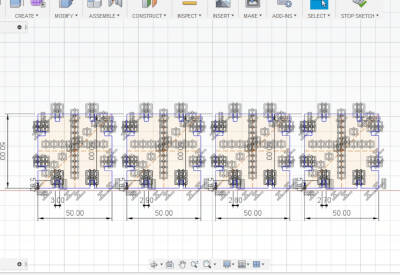
After this, I had a complete parametric design for the blocks. Then, I specified the dimensions of width and height of the original slot and the general width and height of the block. Now, if I change anything on the original slot, the others change automatically.
Preparing the file
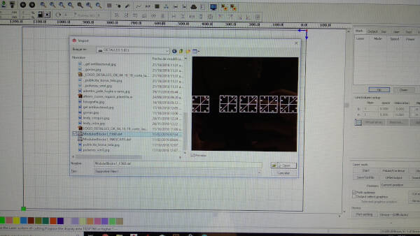
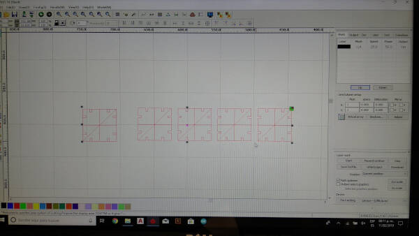
The software that the Lasercutter uses is RDWorksV8.
This are the steps I followed for preparing the file to lasercut:
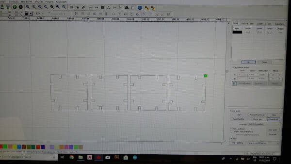
- 1. Import the DXF file into the software.
- 2. Set the laser cutter parameters. I used Speed 25 mm/s, Power 60%.
- 3. Turn on the machine by turning the keys.
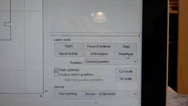
- 4. Click download.
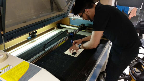
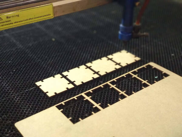
Using the Laser Cutter machine
When I used the laser cutter I had to turn the extractor of the machine. As Neil said in the last lecture, I waited 1-2 mins until all the fumes were extracted and then I opened the door of the lasercutter.
I also used 4mm cardboard to make the kit.
And this is how the modular kit looks like in 3mm acrylic. This material was more fragile on the edges, so sometimes when I snapped the blocks together, It would break. I'm thinking that's because the slots are too near to the edges.
Update: Parametric design
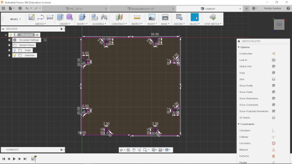
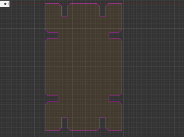
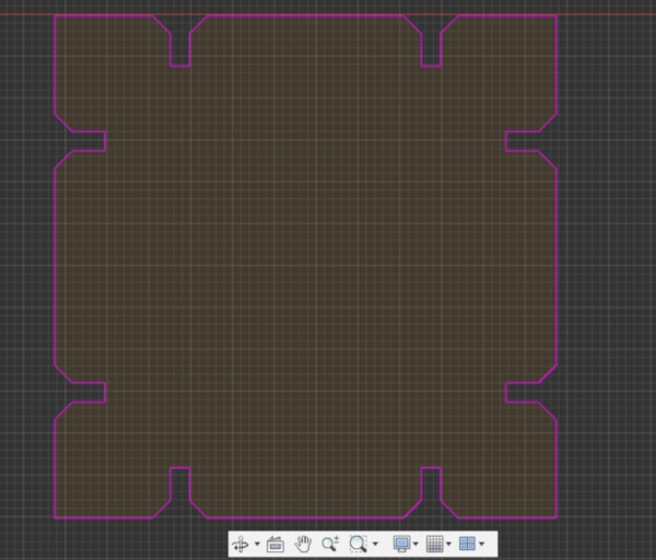
As I noticed in after assignments, the mirror function I used is not really a parametric design function. Fusion 360 has a parametric design box to create parameters that can be changed and the whole design will change, so I did the update version of the modular blocks using this function. First I created a new design and redrawed the same shape of the blocks as before.
Then, under the Modify tab, there is a Change Parameters function
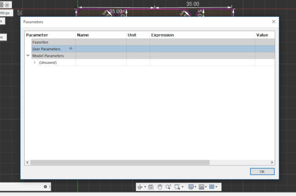
I created a width, height, kerf, and thickness parameters.
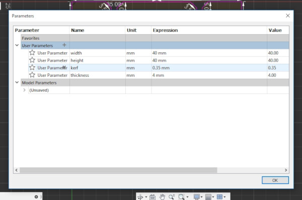
Then, using constraints as collinear, for the lines that should be parallel and over the same line, perpendicular, for the 90 degrees lines, and equal, for the same distance lines, I assigned distances for the different lines of the shape. For example I used a function: thickness-kerf*2 for the slot width, and width/2 for the half of the width.
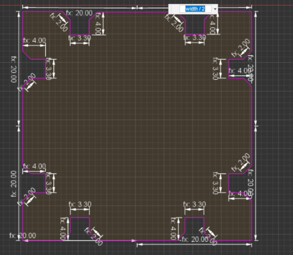
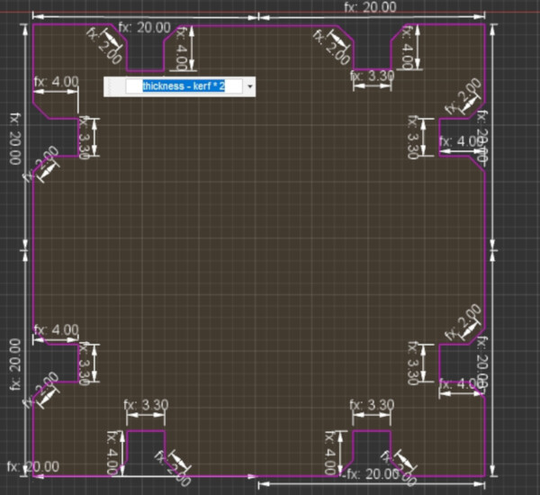
After assigning this, I can now change any of the parameters (width, height, kerf, thickness) and the design will change.
This new design is now on the Files section at the bottom of this page.
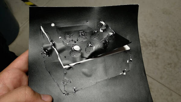
Vinyl Cutter
At first I tried to vinyl cut what I designed last week to make a sticker. So this first approach didn't work at all, because the design wasn't ready for this. When you vinyl cut a digital drawing, you have to make sure that you have a thick line that is vectorized, so the knife don't goes above the vector, it goes on the edges of the lines.
At first I had the original design in Illustrator with the line thickness of 0.25pt, then I tried it with 3pt, but this isn't a real difference for vinyl cutting so neither worked.
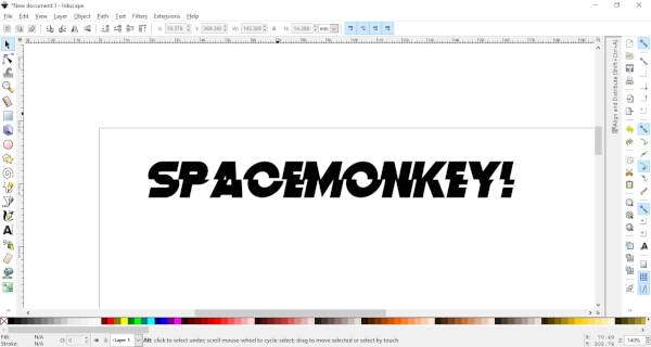
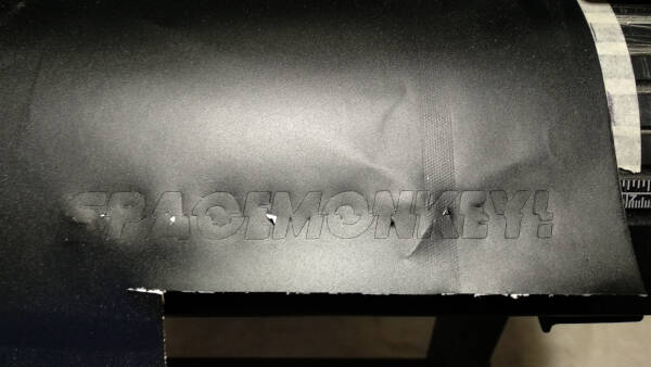
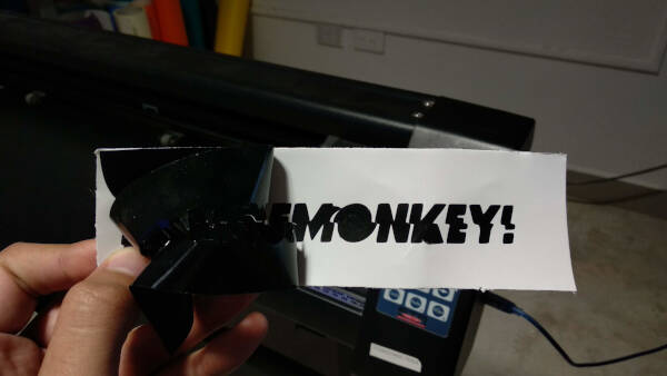
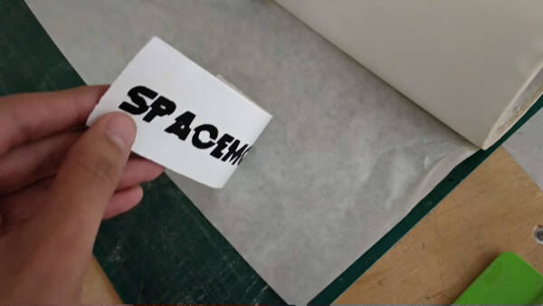
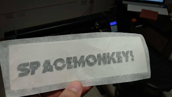
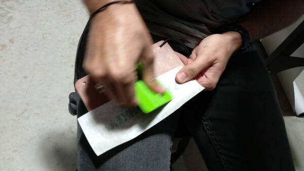
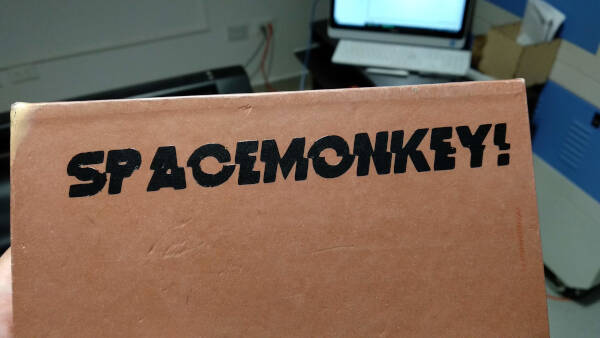
So I tried something simpler, doing some typo! First I downloaded some cool fonts on DaFont. After installing the fonts (double-clicking them), I used Inkscape to write the text I wanted on my sticker. Then, I selected the option Path > Object to Path, to convert the text into vectors. I exported as DXF.
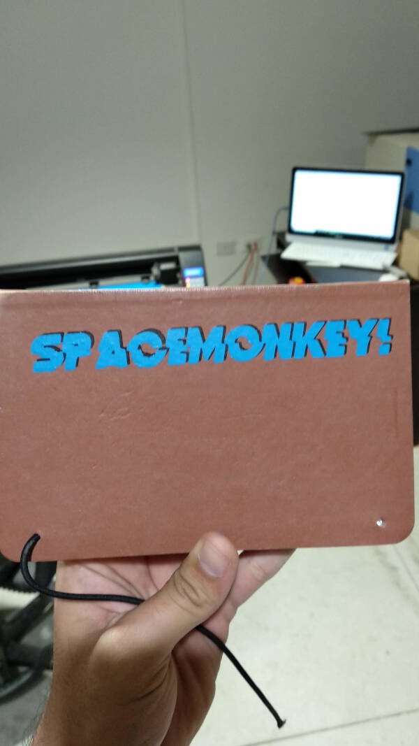
After I saw [this tutorial](https://www.instructables.com/id/Pro-Tip-Vinyl-Cut-Great-Stickers/) on some pro tips and tricks for vinyl cutting great stickers, I figured that adding another layer of different color would make the sticker look way better.
What I missed
- 1. I wanted to use OpenSCAD to parametric-design the press-fit kit.
- 2. I wanted to vinyl cut the designs I made last week but figured the were pretty difficult to do so.
- 3. Making a living hinge on the lasercutter.
Files
ModularBlocks Parametric design .f3d (Fusion 360)
ModularBlocks .dxf
ModularBlocks .svg
Spacemonkey sticker .dxf
Group Assignment
To see this weeks group assignment click here.