4. Computer controlled cutting
This week I worked on 2 main tasks on Computer aided cutting in order to familiarize with both vinyl machine and laser cutter/engraving machine. These were de assignments:
-
Group assignment:
Characterize your lasercutter, making test part(s) that vary cutting settings and dimensions.
-
Individual assignment:
- Cut something on the vinylcutter.
- Design, lasercut, and document a parametric press-fit construction kit, accounting for the lasercutter kerf, which can be assembled in multiple ways.
SUMMARY
-
Have you?
1. Explained how you parametrically designed your files > DONE
2. Shown how you made your press-fit kit > DONE
3. Included your design files and photos of your finished project > DONE
ASSIGNMENTS
Group - Characterize laser cutter machine
General considerations and values about laser cutting machine
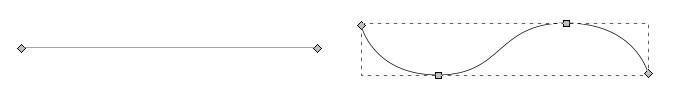
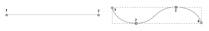
X and Y are the machine movement limitation axes. They can move over the material in a straight line or in curves combining the movements in both axes. Vectors are used for that.
Vectors are a list of sucessive points and interpolations in the (x, y) coordinate system that define the curved and straight lines of the design. They indicate to the machine-head the paths that must follow.
The vector role is crucial to define the job tasks. Lines, areas and colors should be defined in the design during the ‘prepare to machine’ step.
-
How it works
As a general idea, laser cutting/engraving machines work by burning materials whit a laser-head controlled by computer in 2 dimensions (width and height).
As laser cutting/engraving machines could be used to mark, engrave and cut materials, the vector role is crucial to define the job tasks. Lines, areas and colors should be defined in the design during the ‘prepare to machine’ step.
-
Main jobs and parameters
Basically, laser cutting/engraving machines work with 3 parameters: laser intensity, laser-head movement speed, and laser frequency.
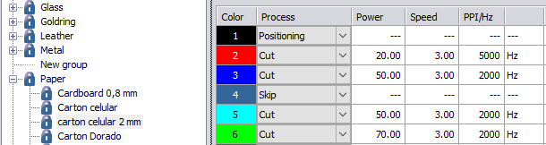
According to the desired results, the machine settings could be varied freely. The main difference on laser work results lies in ‘intensity vs speed‘ values setted up to decide what depth on material the laser will reach. Although, there is one basic rule to be considered to think the result of the design on the material: line vs area, which means mark/cut vs engrave. The reasonable rule is:
- LOW Intensity + HIGH Speed = marking
- HIGH Intensity + LOW Speed = cutting
This is governed by the ‘amount’ of laser that the material receives at every point of it.
Marking & Cutting >
In both jobs, only vectors without fill are used. The laser-head goes over vector defined paths wich can be points, lines, numbers and letters, a draw/design…
The resultant design depends on laser width (kerf).
The working total speed depends on the complexity of the design and on the material used.
Marking works just on the material surface, ‘printing’ (burning) the design on it.
Cutting goes through the whole material thickness to free from the board the pieces defined by design vectors.Engraving >
On this job, it must be used vectors with fill. The laser-head sweeps from beginning to end of a rectangular area in where the design is automatically inscribed (scan). Although laser-head must travel the entire rectangular surface, it will only burn the material surface within the design fill limits.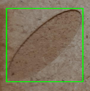
The resultant design depends on fills of the design (area).
The working total speed depends on the fills total area of the design and on the amount of desired bas-relief to be made on the material. Here, the reasonable rule is:- LOW Intensity + HIGH Speed = superficial engraving
- HIGH Intensity + LOW Speed = depper engraving
-
Materials
These are some materials that are recommended/not recommended to be used in laser cutting/engraving machines. (source)
-
Not recommended:
- PVC (Poly Vinyl Chloride)/vinyl/pleather/artificial leather
- Thick ( >1mm ) Polycarbonate/Lexan
- ABS
- HDPE/milk bottle plastic
- PolyStyrene Foam
- PolyPropylene Foam
- Epoxy
- Fiberglass
- Coated Carbon Fiber
- Any foodstuff
-
Recommended
-
Cutting
- Many woods
- Plywood/Composite woods
- MDF/Engineered woods
- Paper, card stock
- Cardboard, carton
- Cork
- Acrylic/Lucite/Plexiglas/PMMA
- Thin Polycarbonate Sheeting (<1mm)
- Delrin (POM)
- Kapton tape (Polyimide)
- Mylar
- Depron foam
- Depron foam
- Gator foam
- Cloth/felt/hemp/cotton
- Leather/Suede
- Magnetic Sheet
- NON-CHLORINE-containing rubber
- Teflon (PTFE)
- Carbon fiber mats/weave
- that has not had epoxy applied
- Coroplast (‘corrugated plastic’)
-
Etching
- Glass
- Ceramic tile
- Anodized aluminum
- Painted/coated metals
- Stone, Marble, Granite, Soapstone, Onyx.
-
-
-
Applications
Laser cutting/engraving machine could be used, as shown, to do 3 main jobs on materials. According to this, its commonly uses are:
- Plain designs (any 2D design on most materials)
- Foldings (cut-outs, origami, paper crafs on soft materials)
- Textiles (dresses, footwears, accesories)
- Furniture (functional modular utilities to take advantage of space use on most contexts and materials)
- Art and Objects (expressive and functional pieces on most materials)
- Industrial design (precise and functional objects on most materials)
- Structures (engineering/architecture installations and models)
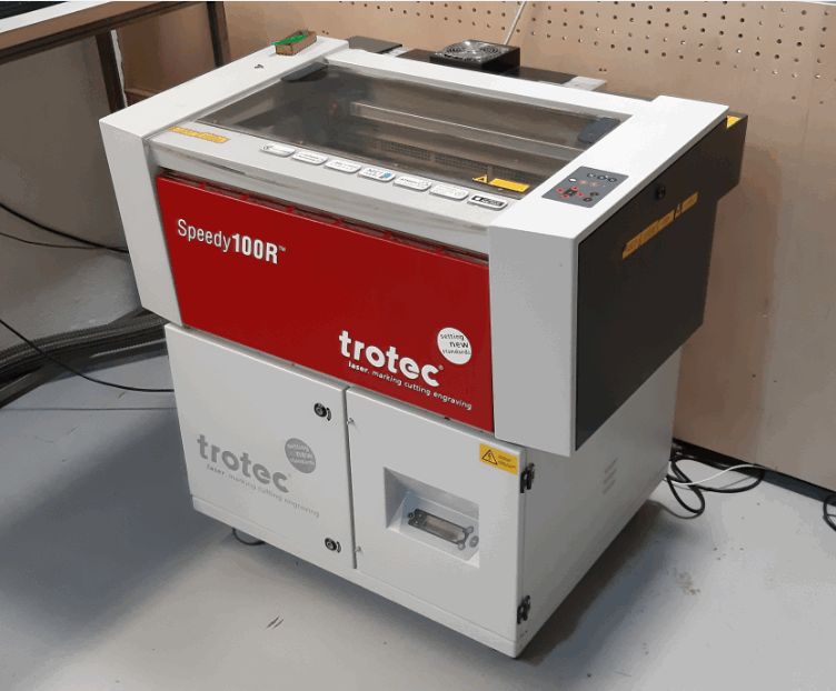
Machine description
The laser cutting/engraving machine I used to do the assignment is a Trotec Speedy 100R, which basic technical data is this (source):
- 50 W CO2 laser (Iradion tube)
- 2 inch lens (standard) changed by 2,5 inch one
- 61cm x 30.5cm working surface
- 180 cm/sec speed
- Box size: 982 x 780 x 457 mm
- 80 kg
- Air cooling
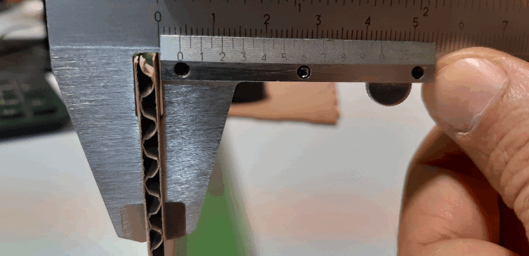
Material description
For this assignment I used 4mm thickness corrugated cardboard.
Design description
There were 2 designs to be made for the laser machine assignment:
-
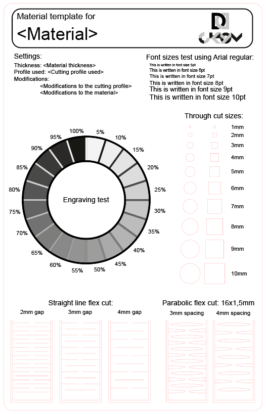
Laser cutting/engraving machine testing designs
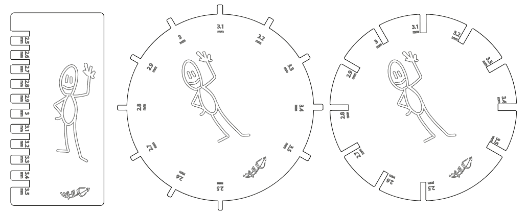
I used a kerf and also a general laser-test template. Also my own design to test joints:
To calculate the kerf I used a formula applied by another Fab Academy students on past years:
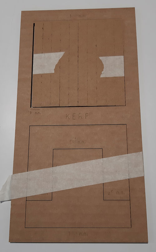
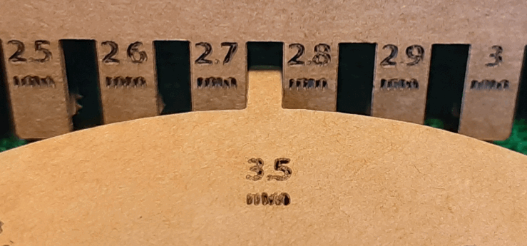
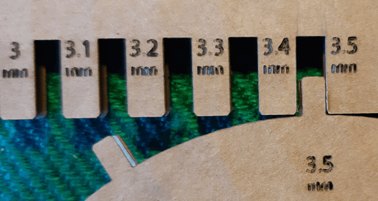
Kerf Test
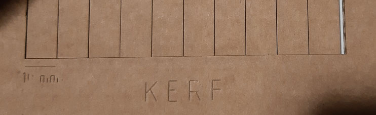
For the kerf test, we used the data collected above to have the lowest kerf. So the minimum speed with a clean cut, we used the same template for all materials which consists of a square with 11 cuts inside, to calculate the kerf we used the formula of deducting the width of the stacked cut bars (A) from the interior width of the square they were taken from (B). And since we had 11 cuts the equation would be:
Kerf= (A-B) / 11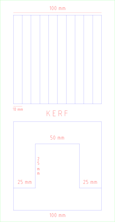
The idea with this general template is to test the 3 main jobs by material, in a unique board. You can see also resolution vs size and ‘living hinge’ behaviour.
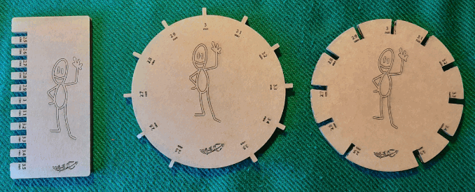
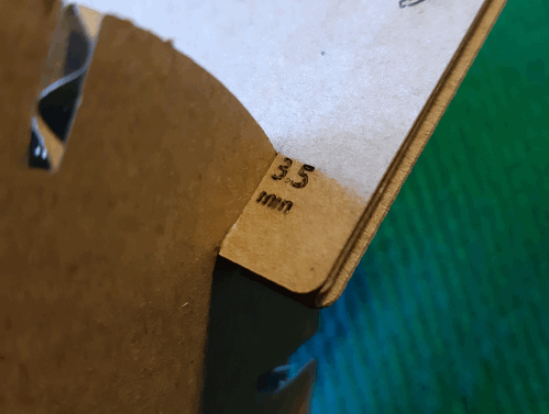
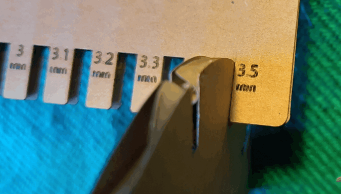
My desing intends to clarify the specific size that my material needs to press-fit without falling off (avoiding glue and others). I made also a stand-out parts version to test it over more than with material thickness, which could be less exactly than the mesure itself.
-
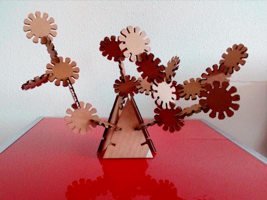
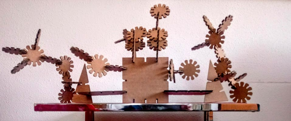
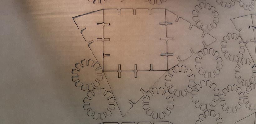
Parametric press-fit construction kit
This is my own press-fit construction kit:
The idea is to use 5 shapes (square, circle and 3 triangles having 30, 45 and 60 degrees) to combine them in order to change the plane orientation of the final result. It was firstly done on Illustrator and then done again on Fusion360 to make it parametric.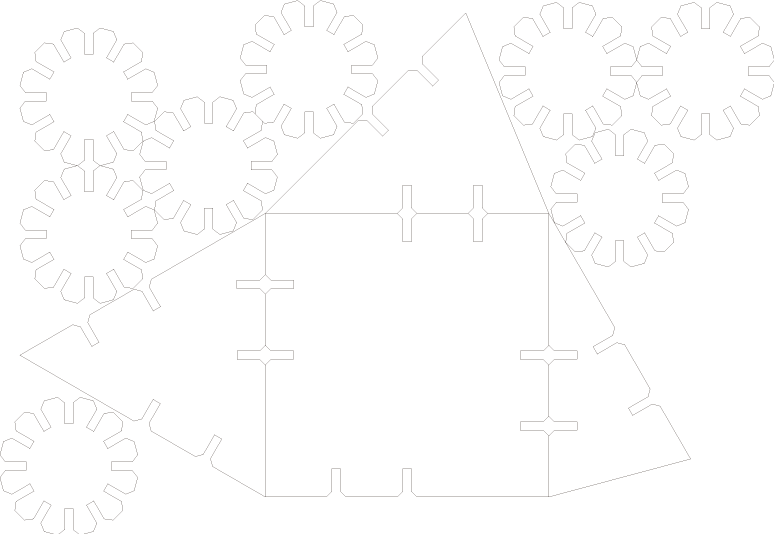
Process
Here are the followed steps to do he assignment:
- Review material > Cardboard size: 1400 mm * 1000 mm and must be cut to laser-bed size: 600 mm * 300 mm
- Prepare design > Used (and tried to use…) Illustrator, inkScape and freeCAD
- Prepare laser cutting/engraving machine file(s) > Selected vector colors and thickness, also sheet size to laser-bed size
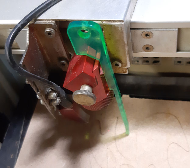
- Calibrate focal distance (z axis) in laser cutting/engraving machine > Used fablab self tool
- Prepare materials in the bed of the laser cutting/engraving machine >
- Send file(s) to the laser cutting/engraving machine >
- Test operation >
- Check operation and results >
- Readjust (in needed) machine settings/material/design/laser machine file(s) >
- Start and monitor job(s) >
- Wait job(s) to be finished and laser machine to get stop >
- Clean cutting debris on the machine and parts >
- Secure the workspace (turn-off the machine, close door…)
- Test design >
Results
These are the testing results of laser cutting/engraving machine:
-
Laser test
Raster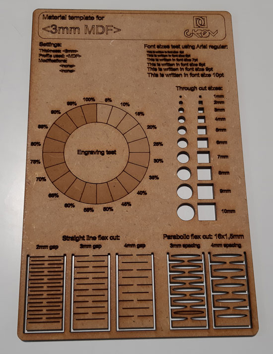
Laser templateKerf test
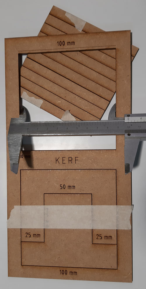
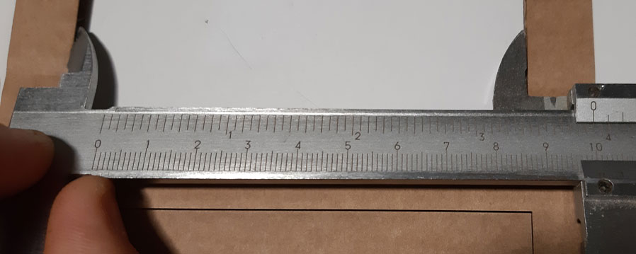
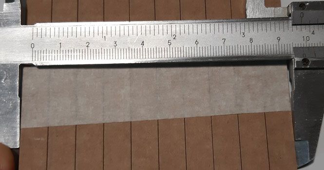
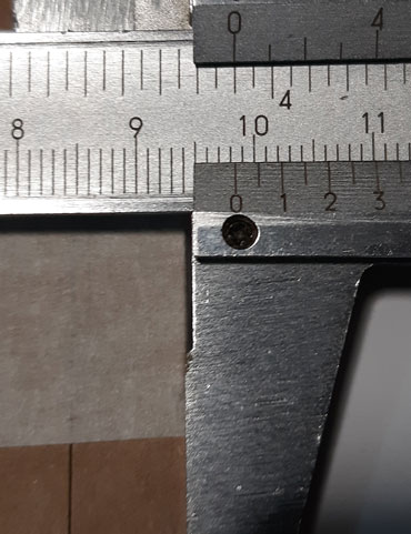
Kerf=(A-B)/11 so if A=99.9 and B=98.3 > Kerf=(99.9-98.3)/11 = 0.1454545… mm
-
Material test
These are the press-fit construction kit results on laser machine:
UPLOAD PENDING
Conclusions
Trotec Speedy 100R laser machine on 4mm corrugated cardboard reports this main pros/cons conclusions:
-
PROS
- Speed/Precision
- Laser-head remote control
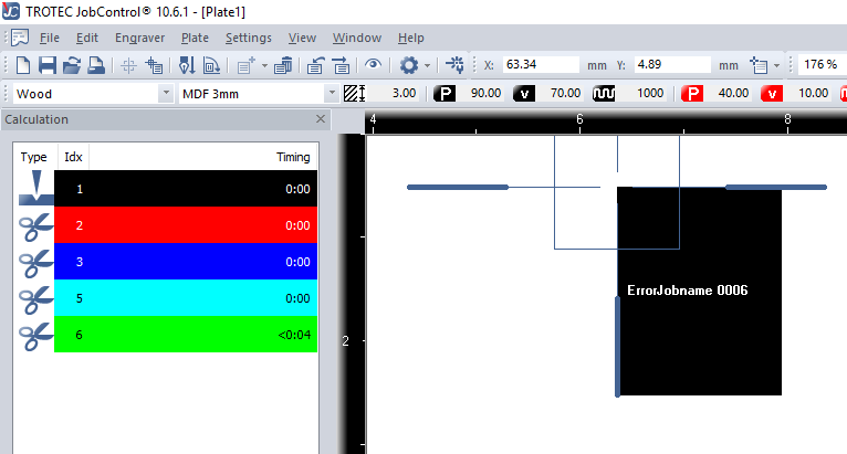
- Printer driver (JobControl)
-
CONS
- Small laser-bed
- Does not pre-scan job area
- Noisy cooling
Individual - Vinyl cutting
General considerations and values about vinyl cutting machine
-
How it works
As a general idea, vinyl cutting machines work by cutting materials with a rotatory blade controlled by computer in 2 dimensions (width and height). X and Y are the blade movement limitation axes.
-
Main jobs and parameters
Basically, vinyl cutting machines work with 2 parameters: speed, and strength.
According to the desired results, the machine settings could be varied freely. There is one basic rule to be considered to think the result of the design on the material: you will have a positive and a negative vinyl cut from the design. The reasonable rule is:- Simple designs = HIGH (Speed + Strength)
- Complex designs = LOW (Speed + Strength)This is governed by the ‘time’ the blade has to rotate to follow the vector.
Cutting >
Does not go through the whole material thickness (or is not recommended) to free the pieces defined by design vectors. The blade must only cut the adhesive layer. -
Materials
These are some materials that are recommended/not recommended to be used in vinyl cutting machines.
-
Applications
Vinyl cutting machine commonly uses are:
- Plain designs (any 2D design on most materials)
- Foldings (cut-outs, origami, paper crafs on soft materials)
- Textiles (dresses, footwears, accesories)
- Furniture (functional modular utilities to take advantage of space use on most contexts and materials)
- Art and Objects (expressive and functional pieces on most materials)
- Industrial design (precise and functional objects on most materials)
- Structures (engineering/architecture installations and models)
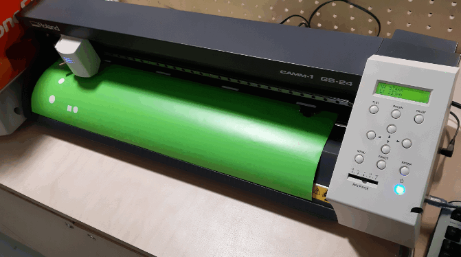
Machine description
The vinyl cutting machine I used to do the assignment is a Roland CAMM-1 GS-24
-
Main specs:
- Driving method > Digital control servo motor
- Cutting method > Media-moving method
- Acceptable media > 50 - 700 mm (2 to 27.5 in.)
- Max. cutting area > Width: 584 mm (22.9 in.) / Length: 25 m (984 in.)
- Acceptable tool > Special blade for CAMM-1 series
- Max. cutting speed > 500 mm/s (all directions)
- Cutting speed > 10 - 500 mm/sec (4 in to 19.69 in/s) (all directions)
- Blade force > 30 - 350 gf
- Mechanical resolution > 0.0125 mm/step
- Software resolution > 0.025 mm/step
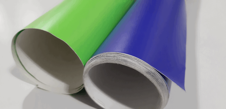
Material description
For this assignment I used apple green adhesive common vinyl.
Design description
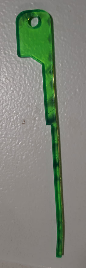
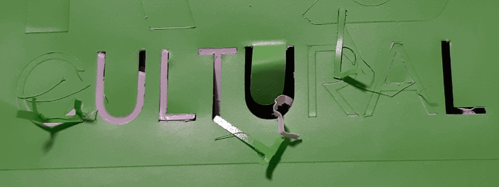
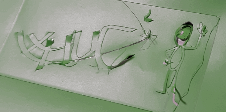
To test the vinyl cutting machine I decided to think in a logo to promote my final project product as merchandising.
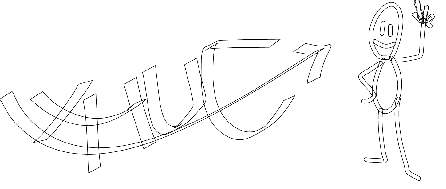
Here is the own design I prepared and used:
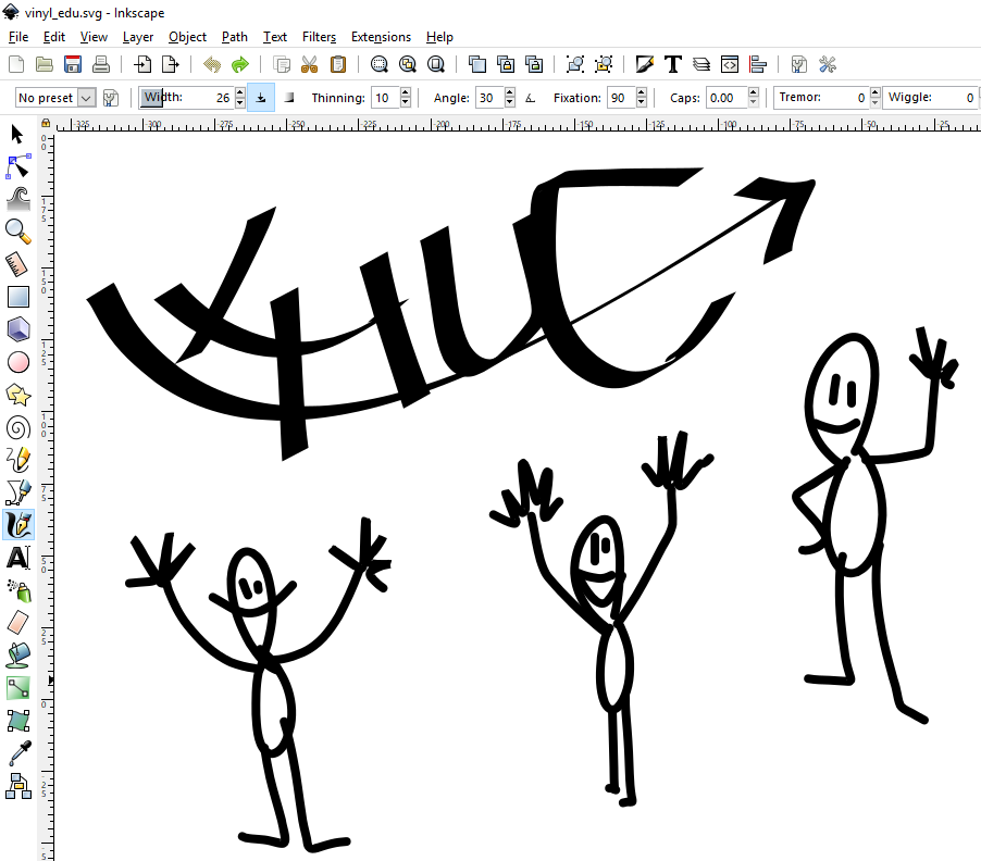
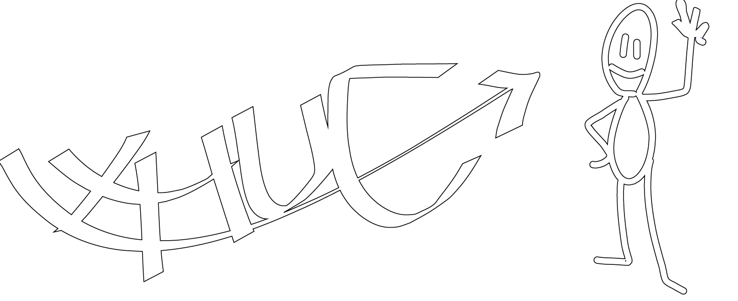
I used Illustrator PATHFINDER to delete overlap and cross lines to prevent the machine to make undesirable job.
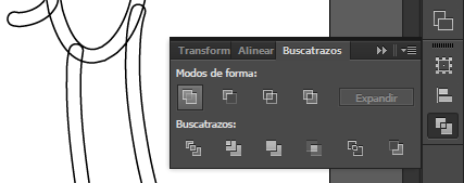
Here is the result of the Unify tool:
Process
These were the followed steps to do he assignment:
- Review material > Used a small piece instead a roll
- Prepare vinyl cutting machine file(s) > Vinyl cutter obtains the vinyl size by a test, so the design workspace can be created from these dimensions
- Prepare design > Used inkScape and Illustrator in the provided sheet size by the machine
- Prepare materials in the vinyl cutting machine > must unlock/lock the material and rollers must be on the white marks
- Send file(s) to the vinyl cutting machine > The cut files are created as printing jobs, that means that the Roland printing driver manages the job directly from the designing software to the vinyl cutter
- Test operation
- Check operation and results > because of the needed calibration of the vinyl cutter, the result is, as shown, a whole material cutoff and also the adhesive vinyl being lifted.
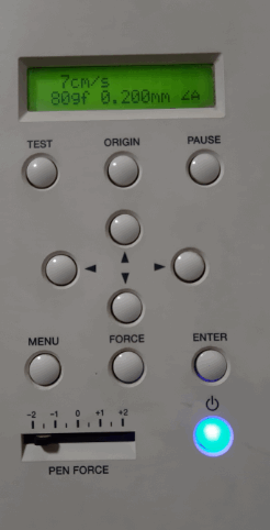
- Readjust vinyl cutting machine settings/material/design (calibrate vinyl cutting machine) or/and vinyl cutting machine file(s) > Decreased strength force from 100 Fg to 80 Fg and PEN FORCE beyond -1
- Start work(s) and monitoring
- Clean cutting debris on the machine and parts
- Test job done > (see results)
Results
These are the final results on vinyl cutter machine:
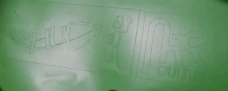
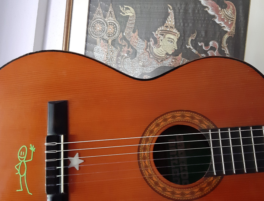
Here is the transfer made to my guitar, very careless because of the high possibility to break the design when removing it from the vinyl piece:

Conclusions
Roland CAMM-1 GS-24 vinyl cutter machine reports this main pros/cons conclusions:
-
PROS
- Fast
- Simple
- Precise
- Vinyl measurement > useful tool
-
CONS
- Printer driver
- A more precise origin setup tool missed
- Vinyl measurement > slow/long vinyl loading process
Individual - Parametric press-fit construction kit
I started my own press-fit construction kit considering these ideas:
- it should offer several different results
- it must be designed parametricaly
- it must account laser kerf
- it must be composed by no more than 5 standard pieces
- it must be composed by surfaces and fixes
- it should be able to combine all 3D planes
- it should consider equilateral triangles
- it must combine 45 degrees rotations
- it could combine 15 degrees rotations
- it is going to be tested with 3mm corrugated cardboard
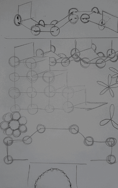
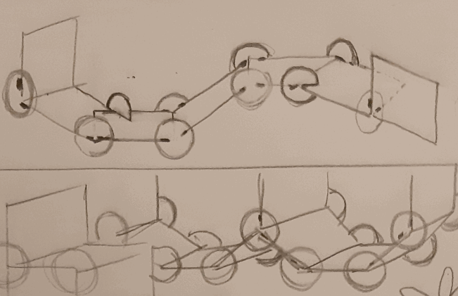
From that, I imagined what examples I could try to test once I had cut the cardboard:
- a car
- a stair
- a support for telephone
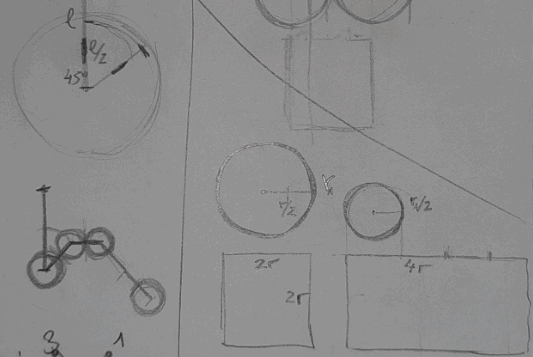
The most difficult challenge was to figure it out in the mind, so I made some sketches to define some basic shapes and possibilities that they could offer when assembling between them.
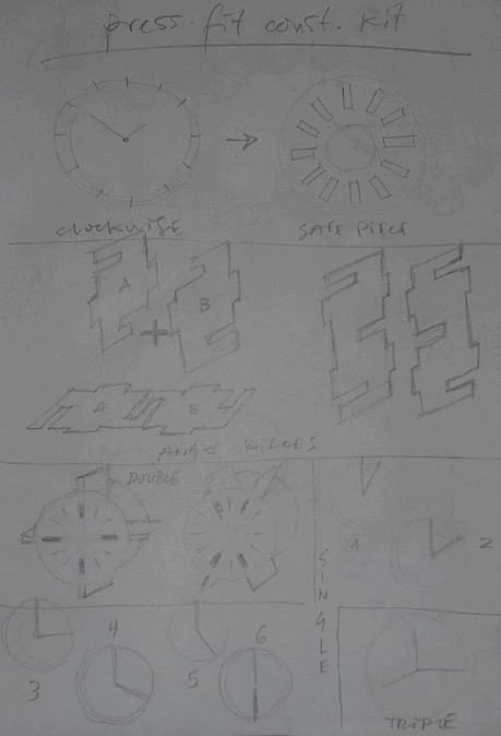
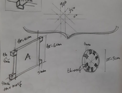
I tried to use freeCAD to achieve the parametrical target, but I am not familiarizaried with it and I began to waste time and to get VERY frustrated :s.
I decided to explore other Fab Academy projects to take advice and I found Nicolo Gnecchi Grasshopper project, which was a software that I was thinking about. His project helped me to give first baby steps to complete and add others parametric variables by my own until my design was done and ready to cut.
And… also I could not achieve my goal because of the problems with booleans. I decided to return to freeCAD rethinking the way to do the design, and all was fine until contraints put my design upside down.
Then I decided to make the design in Illustrator, at least to test the design and maybe those designs could be imported to freeCAD to begin the constraints from a previous design.
By that moment, I did not have more time to work and to document the trying process.
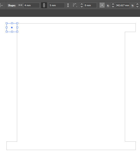
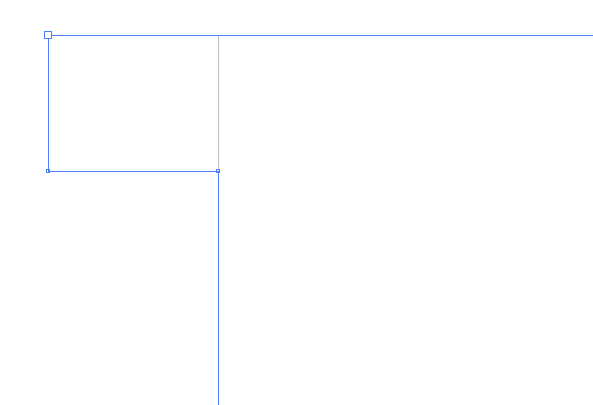
Some Illustrator tries…
UPDATE - PRESS FIT KIT COMPLETED
I made some changes to the design but mantaining the original idea:
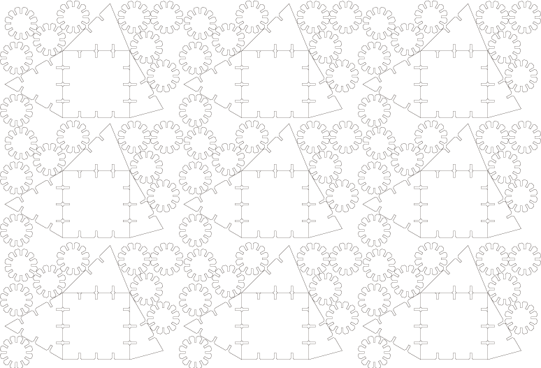
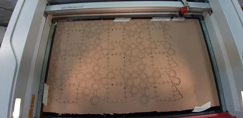
After testing the design with a first cut on the cardboard, I prepared the cut file containing much more pieces to complete the kit:
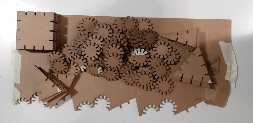
These are the final pieces after the laser process:
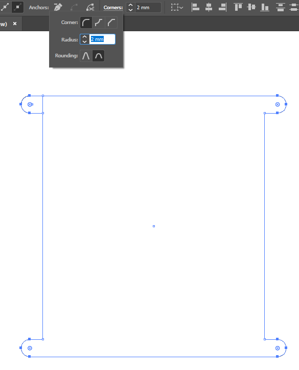
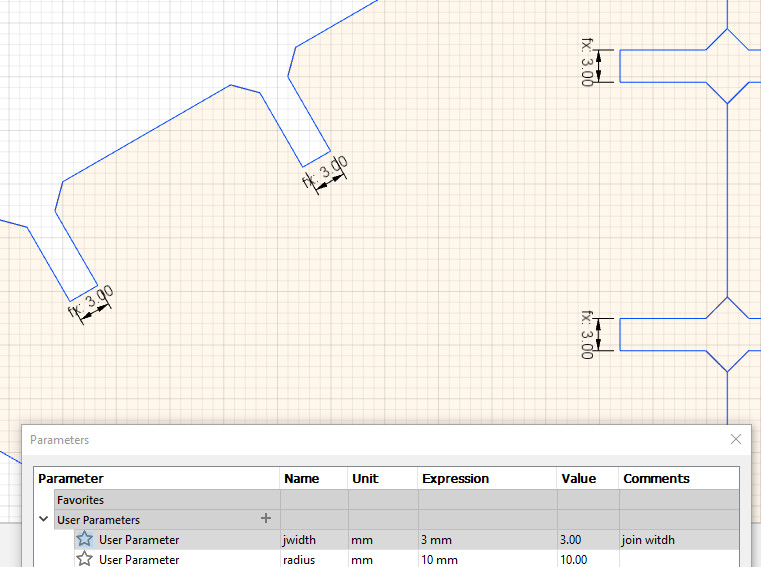
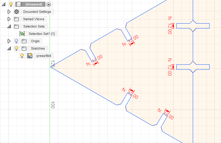
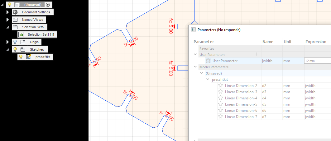
Once the 2D drawings were made with Illustrator, I translated them to Fusion360 to prepare them as parametric drawings.
I had to redraw them again in Fusion360 to avoid problems with constraints and with the application in general:
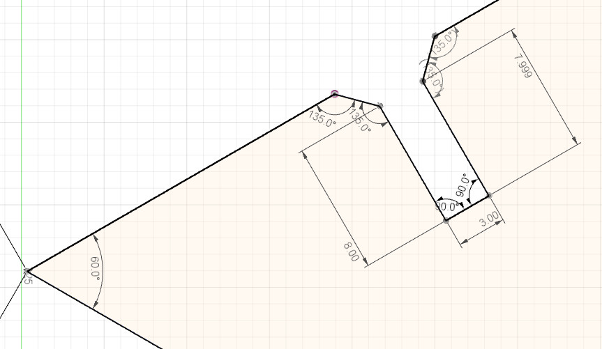
With the Dimension tool I could constraint the distances and the angles and link them to a variable previosuly defined on the spreadsheet.
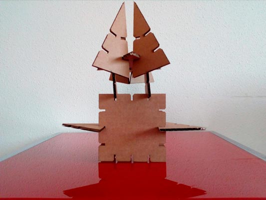
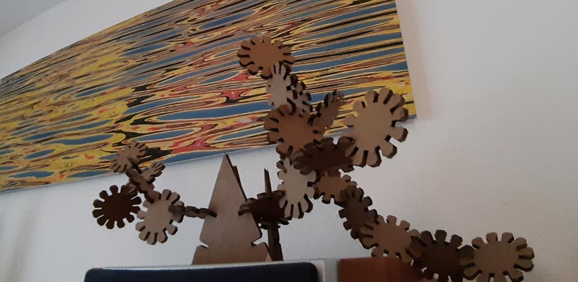
Finally, these are some results of playing with the cut pieces of the kit:
-
Original design files
Laser/Vinyl > All files
Credits
- Abdul Fattah Mohd Tahir / Erween Abd. Rahim - A study on the laser cutting quality of ultra-high strength steel
- Nicolo Gnecchi - Grasshopper project
- ATX Hackerspace Wiki - Laser Cutter Materials
- EduTechWiki - Trotec Speedy 100R
- Noloxs (Thingiverse) - Laser cutting materiale template
- Berytech Fab Lab - Kerf test
- Roland - CAMM-1 GS-24 Specifications