3. Computer Aided design
This week I worked on 1 task on Computer Aided design in order to “evaluate and select 2D and 3D software” and to “demonstrate and describe processes used in modelling with 2D and 3D software”. This helps me to discover new tools and to decide which one I can apply to my project. I tried to draw by computer my first idea of the project. This was the assignment:
-
Individual assignment:
Model (raster, vector, 2D, 3D, render, animate, simulate, …) a possible final project, and post it on your class page.
SUMMARY
-
Have you?
1. Modelled experimental objects/part of a possible project in 2D and 3D software > DONE
2. Shown how you did it with words/images/screenshots > DONE
3. Included your original design files > DONE
-
PENDING
1. Apply discovered design tools to Final Project > DONE
2. Export original design files as .DXF > DONE
3. Add Inkscape video > DONE
ASSIGNMENT | Individual - Graphics!
About CAD (computer aided design)

Something very important in designing figures/objects is the capability to access and edit the design parameters. This is possible through computer aided design, which is the representation of values and formulas describing geometry and the space. Also textures, colors, light, movement and physics are the same idea.
This week I focused on reaching at least one software per category test, according to my project priority and demands.
2D > Raster and Vector
I read about and tested Gimp and Inkscape through some tutorials and I decided to use them as freeware tools for my project. Also I’ll use Photoshop and Illustrator if needed.
-
GIMP (pixel)
It is very capable to work with pixels, and it has a lot of powerful tools to transform and manipulate most pixel image features. It’s a useful and light software to draw and prepare images for publishing, or adding them notes or some special effects with very good results.


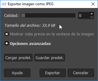
During ‘export as’ you can preview quality vs file size. Original images are heavy for the web, even if you put down the export quality: Example: 34-134-201-1300 = 1670 kB
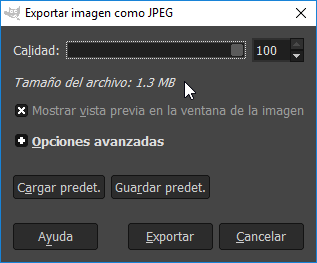
By downscaling the images at 50%, about the 30% of storage is safe: 10-42-63-405 = 520 kB
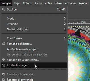
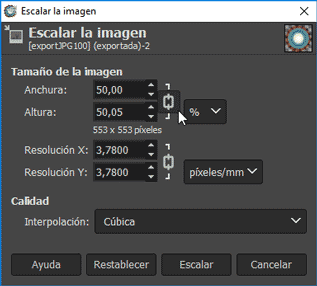
After a 50% downscaling: 34-134-201-1300 = 1670 kB vs 10-42-63-405 = 520 kB
You can export your image at 30 quality value saving a lot of space in disk with usually not much quality difference with the original; much better if you decide to scale your image first.
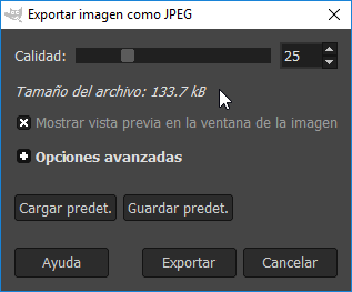
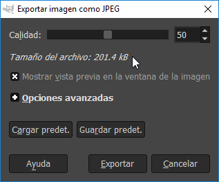
Note in the next images the difference between 0, 25, 50 and 100 quality values. There’s no practical difference between the 2 and 3 images quality. The difference is 20 kB.1
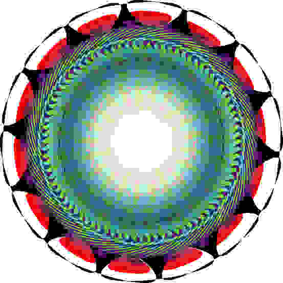
2
3
4
Gimp is useful to work with images as pixels. It works very fluent and has some visible and ready to use special tools which makes tasks easier. On the other hand, I don’t recommend it to work with paths/strokes at all or use it on interchange with that kind of graphics.
Gimp has also a very intuitive and friendly interface which helps to manage the elements and the workspace with modifier parameter views, layers and groups, great labels and icons, actions preview and basic operations (as history, properties and other info) put on scene.
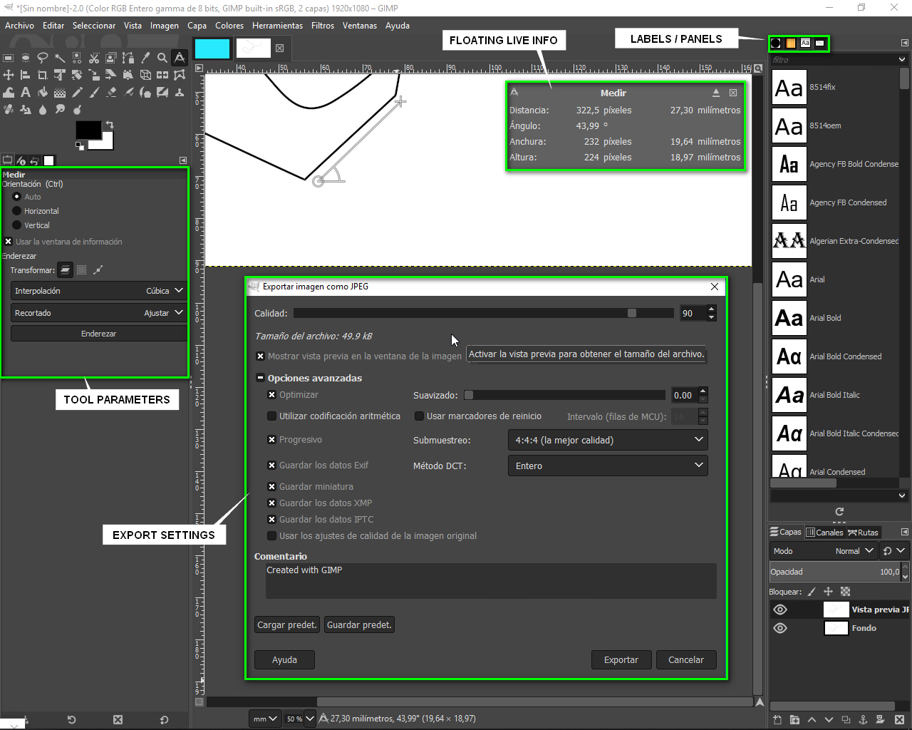
These are some elements of Gimp interface: simple and customizable. -
PHOTOSHOP (pixel)
It is also very powerful and intuitive to work with pixel images, and even with strokes too. It demands a lot of time to acquire experience because of the number of features and settings.
Although it has useful ways to make selections, transform images and apply filters, the most specific features I’m interested in are the Multiple image processing and the Web export tools in addition to the vector treatment.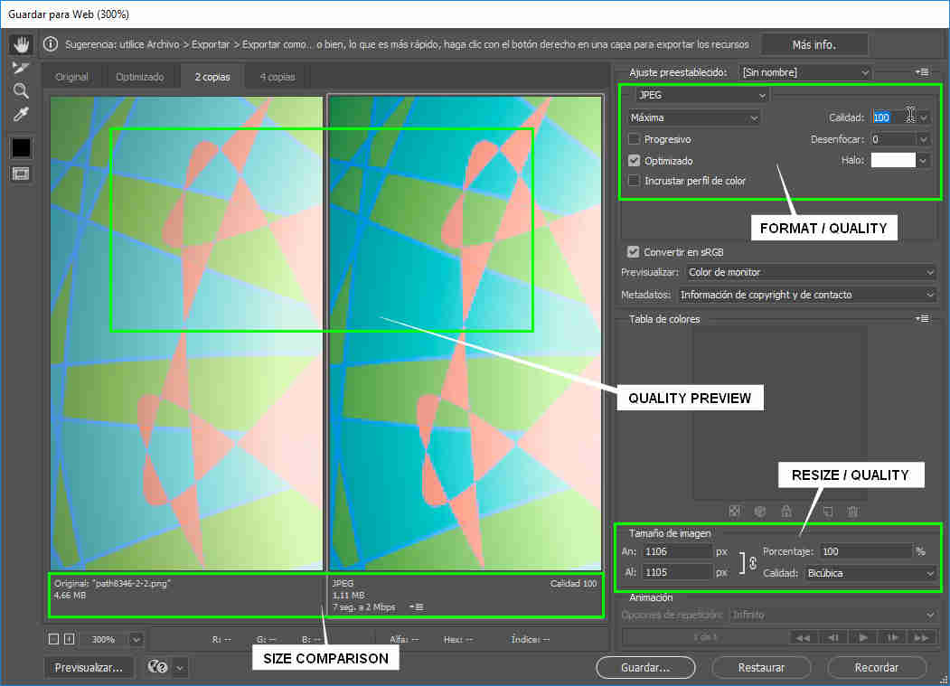
All of them could help me to front a folder full of images, to compare formats and qualities in a unique window and to operate with strokes on selections and visual effects.
I’ll use it only when required. -
INKSCAPE (vector)
It is the only and so powerful free software that I know for working with vectors. It appears to be simple, but ‘hides’ a pack of tools to work very precisely with .SVG files. In my point of view, it is a little bit rude to familiarize with it. Sometimes, the tools work unexpectable and the interface is eventually unpredictable; apart from that, it feels very clear and practical with its complete and useful modifier parameters view/hide docks and managing tools.
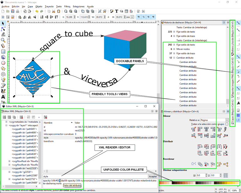
See my Inkscape demonstration:
Of course, it is the one highly recommended to draw vectors and to interchange them with other similar software. It has a very powerful set of tools and controls to manipulate them from technical to artistical. It also has the possibility to work with layer composition and to read/edit the document XML file parameters.
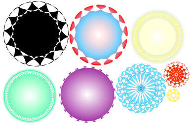
Example of using 1 shape tool (star), adjust fill and stroke, align tool and layer composition.
The three more interesting things I am delighted with apart from drawing are the shape composite, the simplify and the vectorize tools.
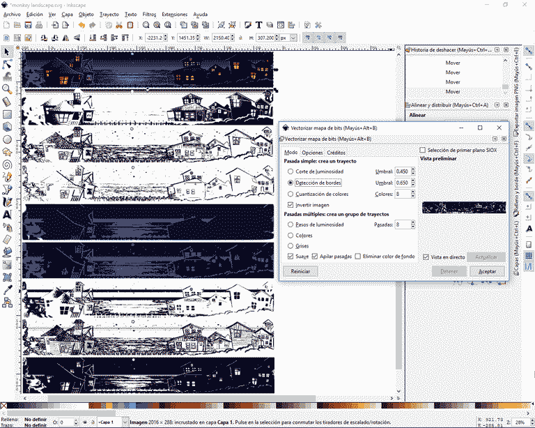
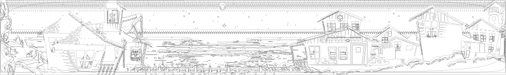
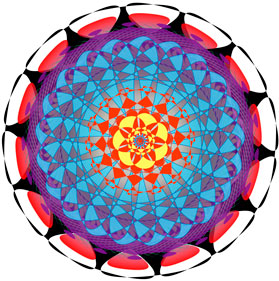
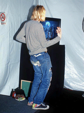
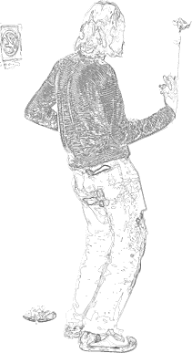
Here I vectorized a bitmap in many ways to obtain most main details of the original image. The result was reached by combinig them and erasing non-useful/overlaped vectors.
-
ILLUSTRATOR (vector)
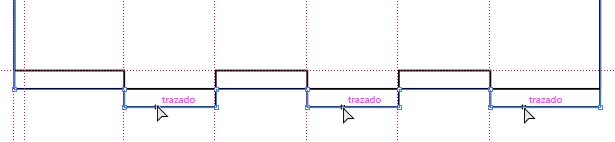
It’s a software with a lot of possibilities. As Photoshop, take experience demands much time and practice, but it works so well for drawing and in measures and references to engage technical drawing. I like so much its anchor/segment/shape/sub-shape operability powered by magnet function and real time info before finishing actions.
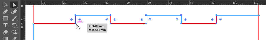
See this simple joint constraint made with the help of rules and guides. Once you have stablished your guides positions entering values y x/y boxes (these must be your object joints measures), you can begin drawing a rectangle and adding it points and moving them to the places where guides crosses indicating the place of the corners of the joints.
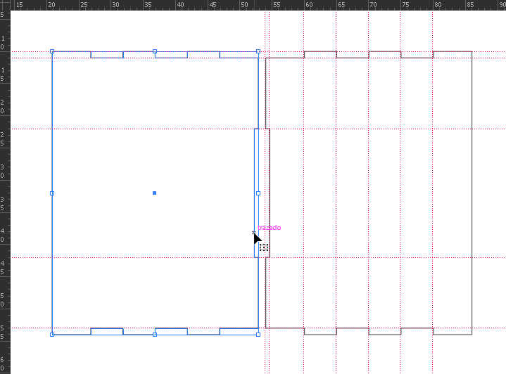
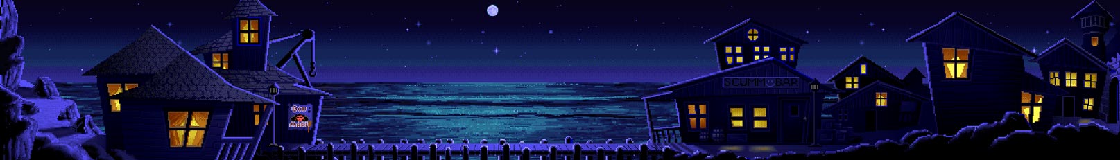
This image shows the beginning of the idea to be reached, started from mirror the shape.
After that is just a process of moving whole parts to the contraints (guides) and to move specific parts (pairs of corners or segments/strokes) to the constraints you are interested in (the measure of your joint). Here is very useful the magnet mode in moves.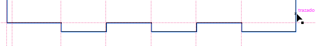
Select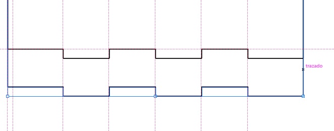
Copy > ALT & dragNote: SHIFT to restrict axis
Move to constrict (could be any part of shapes)Note: the black arrow turns white when finding an anchor, guida, stroke…
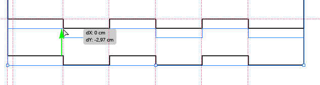
Select segments to be moved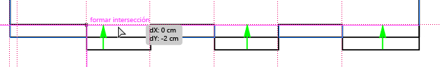
Move them to guide constrict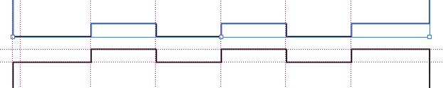
Shapes are ready to joint togetherThis is very easy, fast and helpful for ensure your measures, viewing and editing you design/project at any time, and to prepare your sketches for exporting to another software, laser machine, …
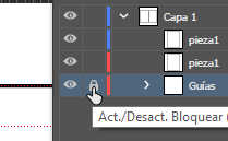
It’s a great environment to manage the drawing in layers, groups and workspaces. A project could be defined entirely in 1 document.
There are also another interesting tools like 3D features and drawing on perspective, or very useful combination and shape interaction tools as Pathfinder.
Vectorizing a bitmap, you can combine results by layers and edit a final stroke.

3D > Tridimensional model
I explored freeCAD and openSCAD freeware throught simple tutorials in order to compare them with Rhino and 3DS Max, which are the softwares I used to work with.
I’ll probably use freeCAD because of its multiple possibilities with parametric design and because is the one I’ve tested more. Both (openSCAD & freeCAD) demand on me more practice and tuto-learning. Also I would like to explore fusion360.
Finally, if needed, I’ll use animation and mentalRay rendering tools in 3DS Max, and also some modeling tools in Rhino.
-
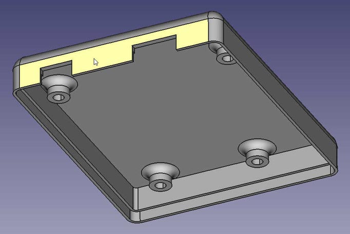
freeCAD (parametric 3D)
It’s a very powerful tool which works directly from parameters and constraints, as shown.
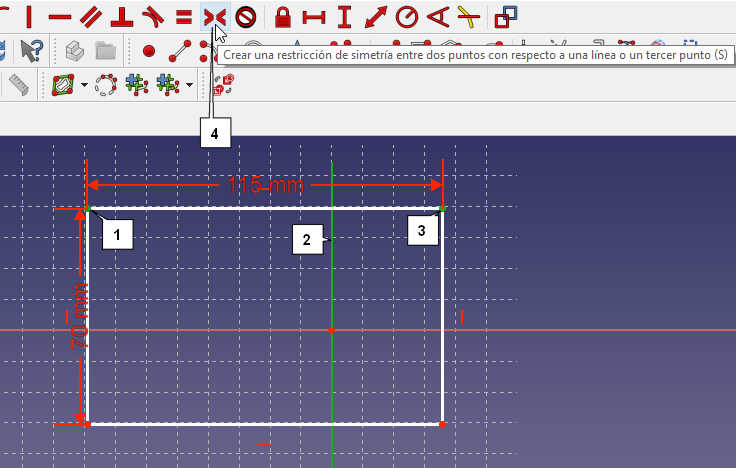
This step is necessary all the time, to apply symmetry to constraints and positions of geometry.
You can create variables in a spreadsheet to be applied as constraints or measures.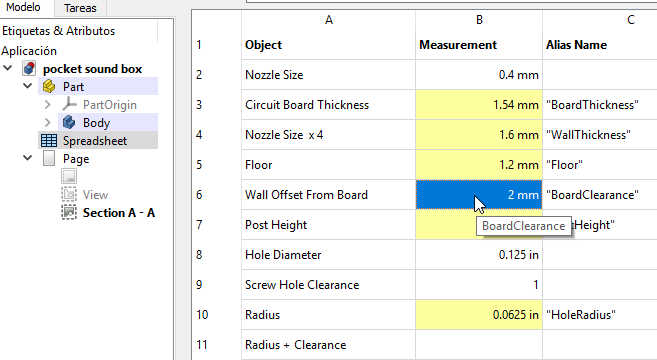
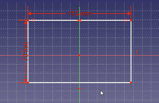
I’ve followed an Arduino case tutorial from mathcodeprint which helped me to know the basic commands to apply them to my own design. The first task is to create an sketch in 2D view with measures and constraints.
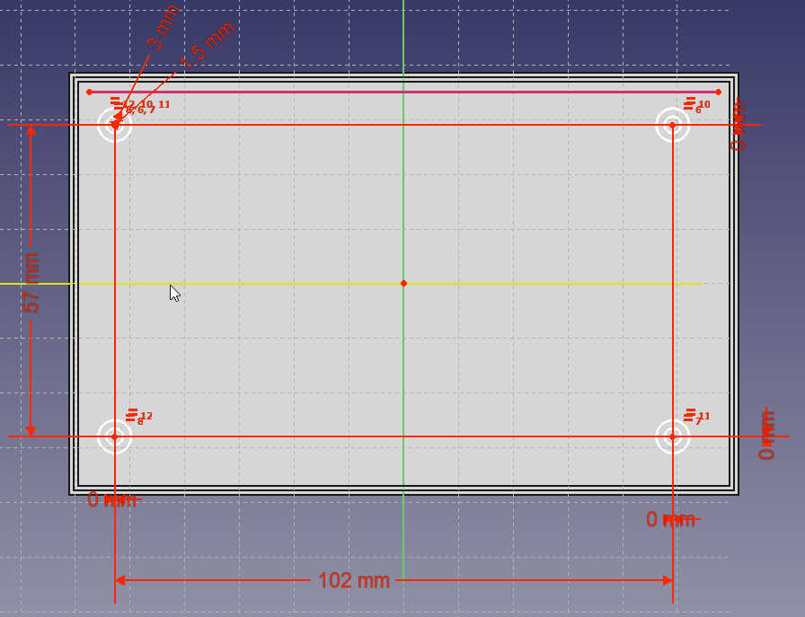
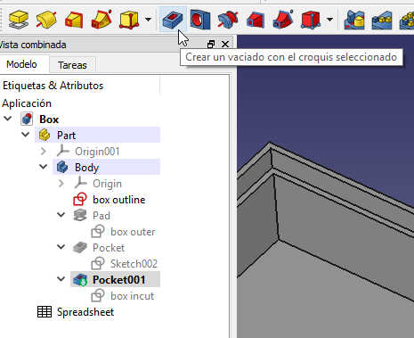
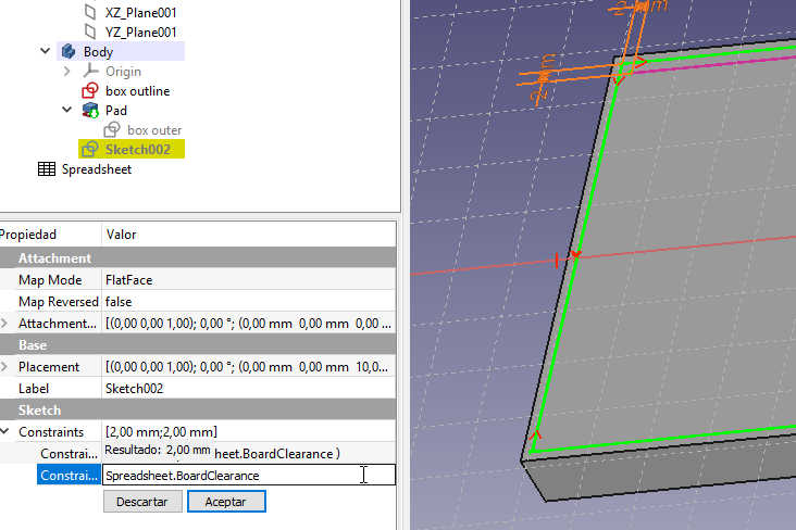
Then, I had to create a PAD to extrude the drawing to after apply it a POCKET. By this way, I obtain same results as the difference Boolean.
-
Original design files