Wild Card Week 17
Introduction
- For this week, we had one main task: Design and produce something with a digital fabrication process that we didn't cover before.
- I worked on two different projects: flexible circuits and screen printing.
Project 1: Paper/flexible Circuits
- For this week's assignment I had an exciting idea in mind. I'm obsessed with flexible electronics, integrating electronics in flexible materials like fabric or paper. My intial idea was to work on something wearable, but we didn't have a digital embroidery machine at Fab Lab Egypt. And even if we did, we didn't have conductive thread that can be used to sew the components in place. So this idea was not feasible. So I went to the next closest thing which is paper electronics.
- Paper electronics have grown from Jie Qi's work for the how to make almost any thing class at MIT.
- I was specifically inspired by her interactive painting project. Electrconics are integrated in a wall painting of blow ball flowers. With an input sensor, a microphone, a person blows and a lighting pattern is triggered to simulate flower patels flying away.
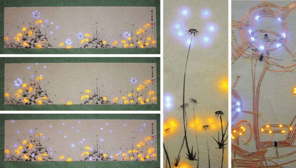
- My idea for this week is to create a miniture version of that painting. The electrical wiring in paper circuits are usually made with copper tape that is routed by hand to make the desired patterns.
- I thought of turning this from a process that is done by hand, into a process that can be done by digital fabrication. The perfect digital fabrication tool for that job is the vinyl cutter.
Experimentation with flexiable circuits
- I started from a previously prototyped simple paper card that I routed by hand. On the cover of the card a robot that blushes when you press on it's heart! The underlaying circuit is simply a couple of LEDs and a battery. The flexibility of the copper tape facilitates folding the paper to close the circuit, as shown below.
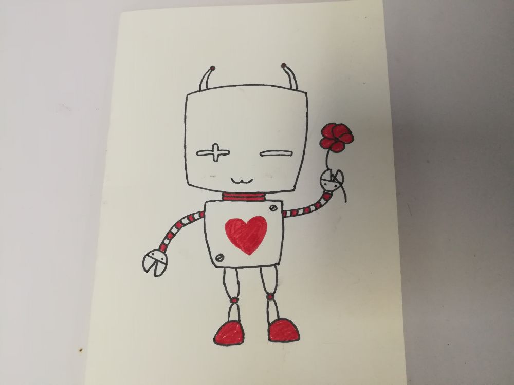
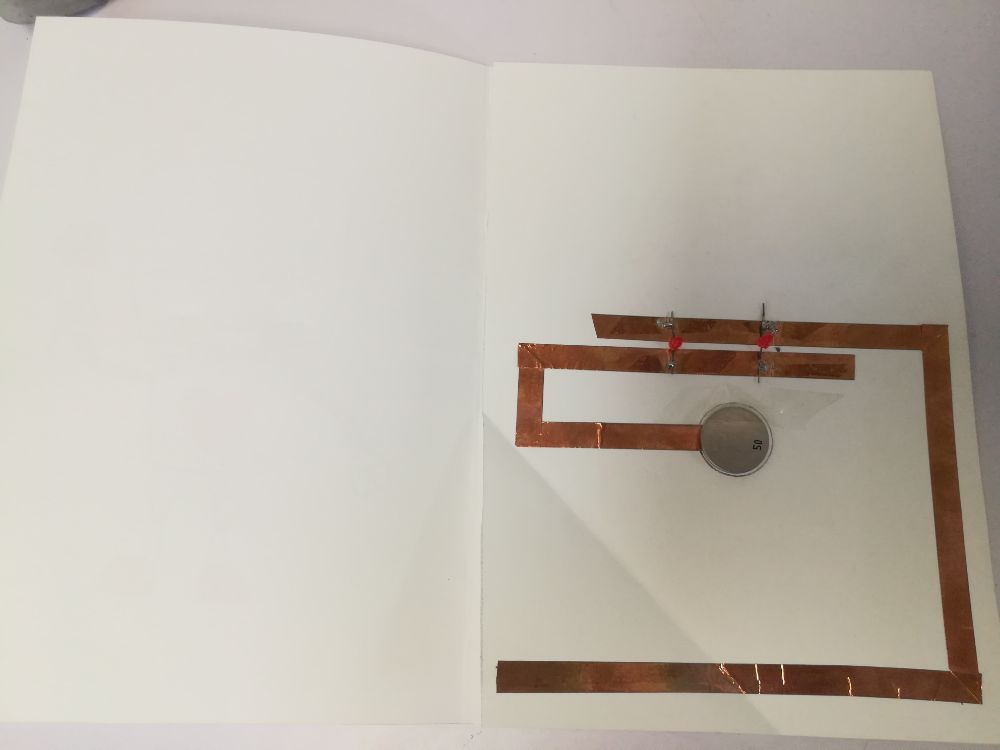
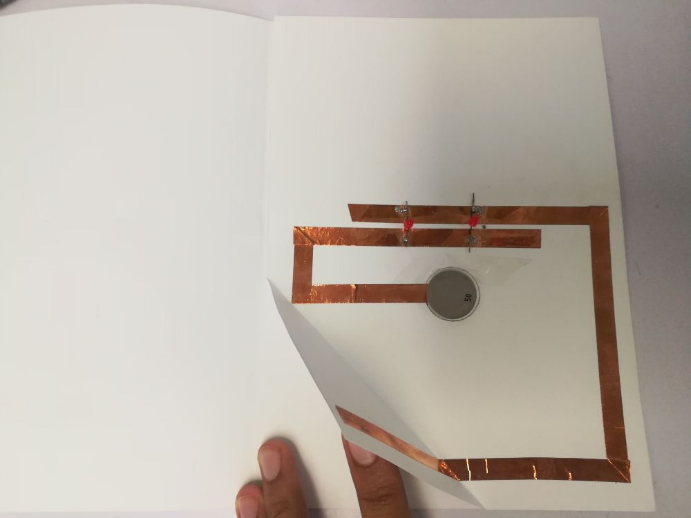
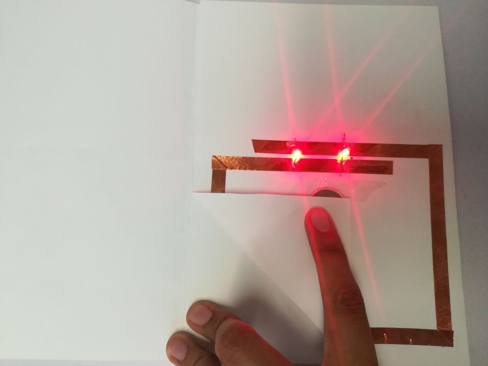
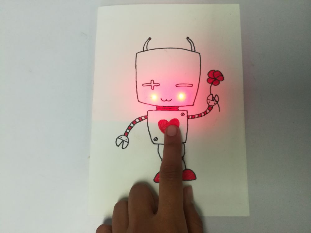
- The card in action:
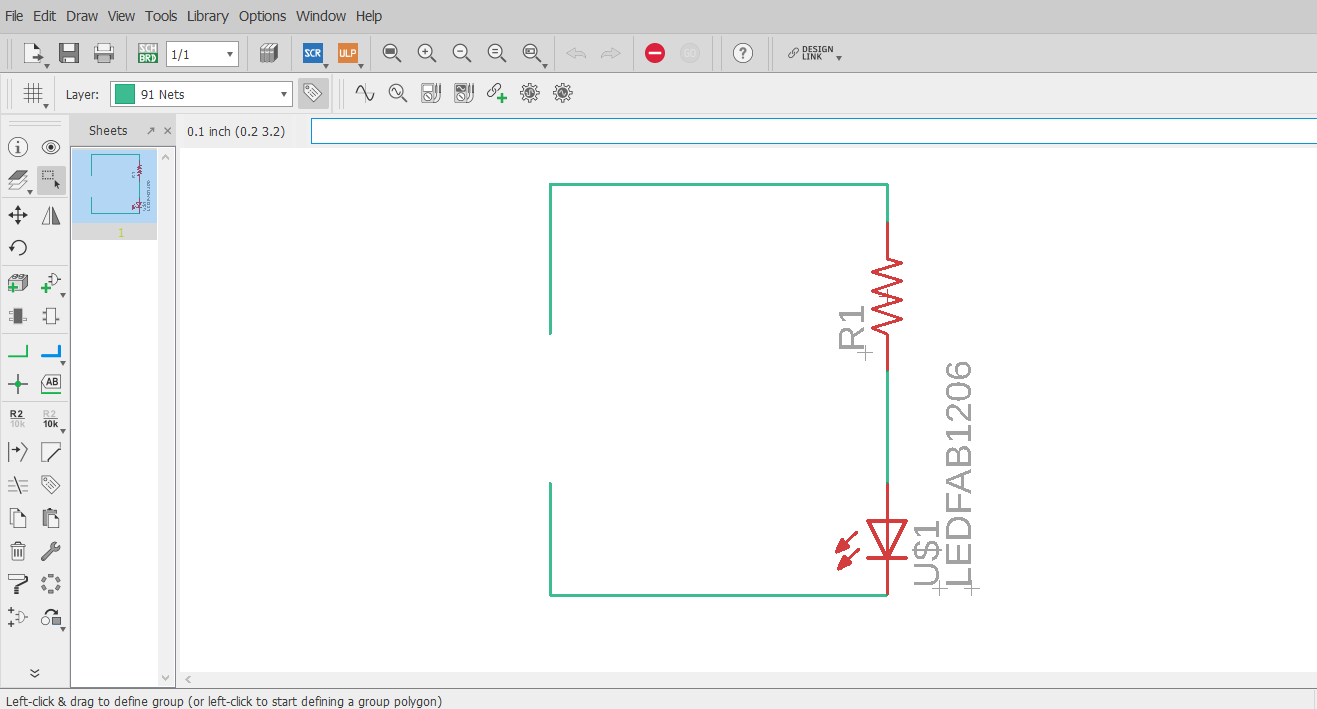
- To do this process digitally, I used Eagle to design a simple circuit with an LED and a current limiting resistor. I kept the circuit open on purpose, to accomodate for the folding space later.
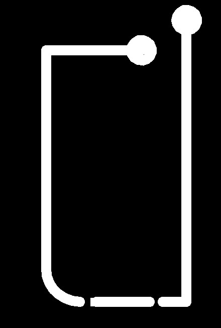
- I switched to board view and drew thick routes with a width of 100. At the ends of the routes I drew circles to act as pads for the coin cell battery that will power the circuit.
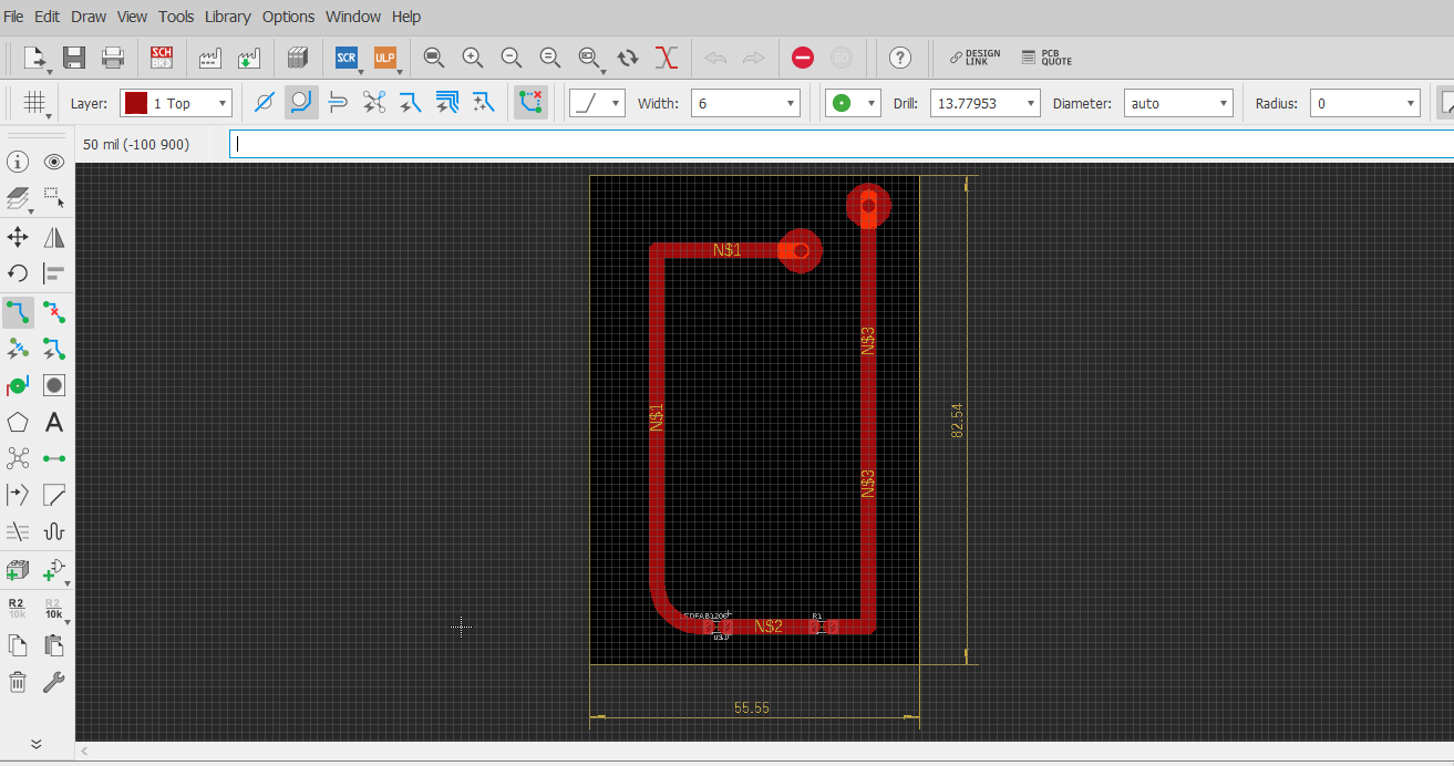
- I exported the board's image, and started to experiement with it on the Vinyl cutter.
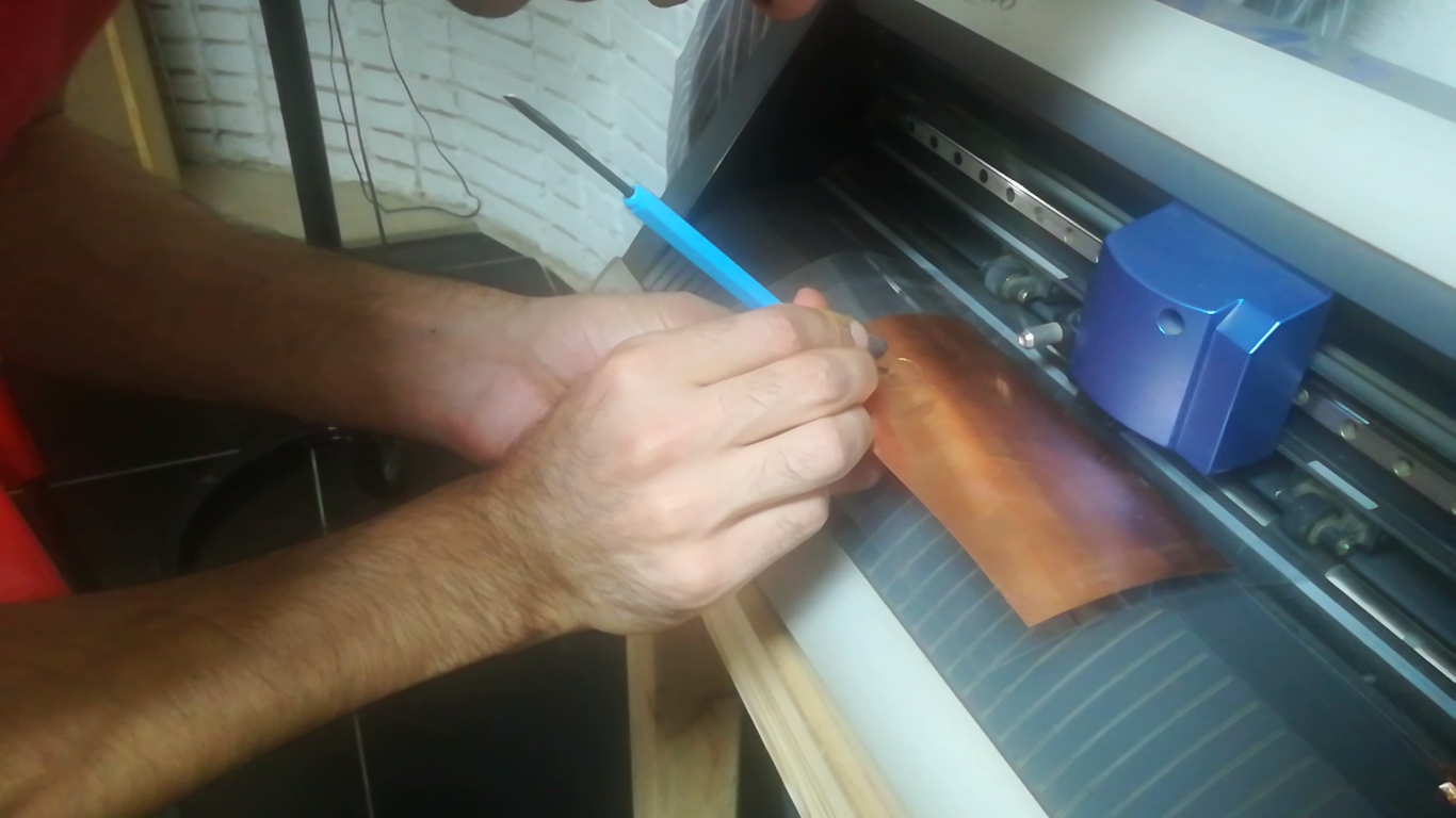
- This was my first time working with flexible copper in vinyl cutter, but from other classmates' experience, using stencil as a scaffold or support was very helpful in preserving the board's structure and routes in place.
- So first, we pasted a piece of copper on the transparent stencil paper, and ran the machine automated test (cutting a circle with a square inside). Trying to remove the cut out copper from the stencil's surface has proven to be challenging.
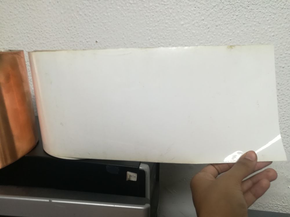
- We thought of using a middle layer of white vinyl between the copper and the stencil. By repeating the same test with the vinyl layer, removing copper from the vinyl surface was much easier.
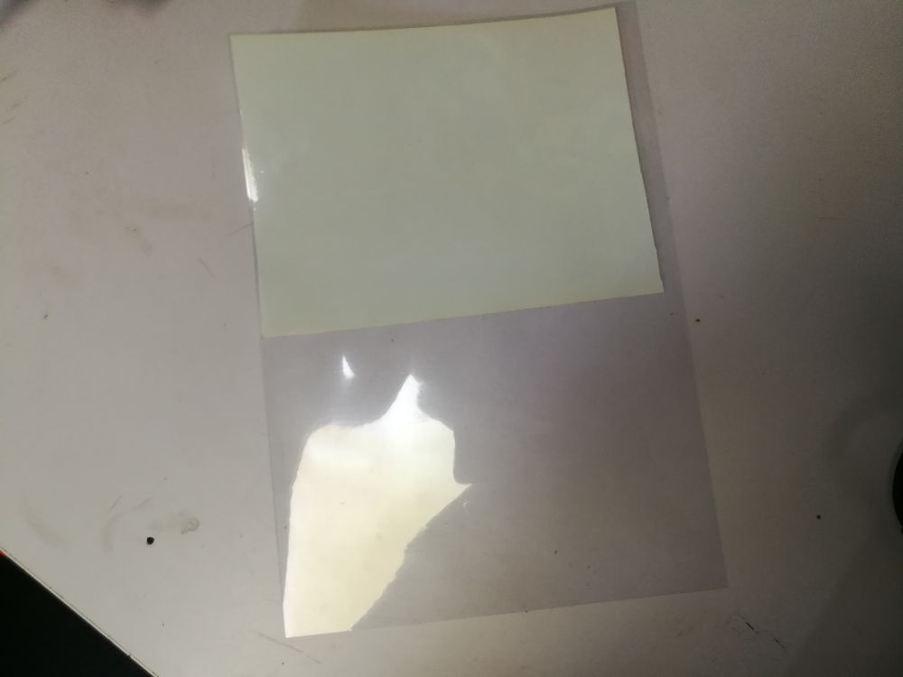
- The vinyl cutter cut the pattern very well.
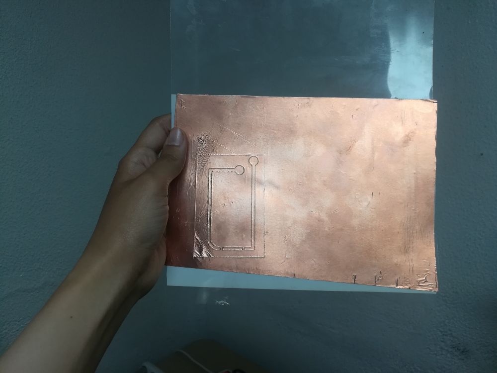
- Then, we removed the extra copper around the traces.
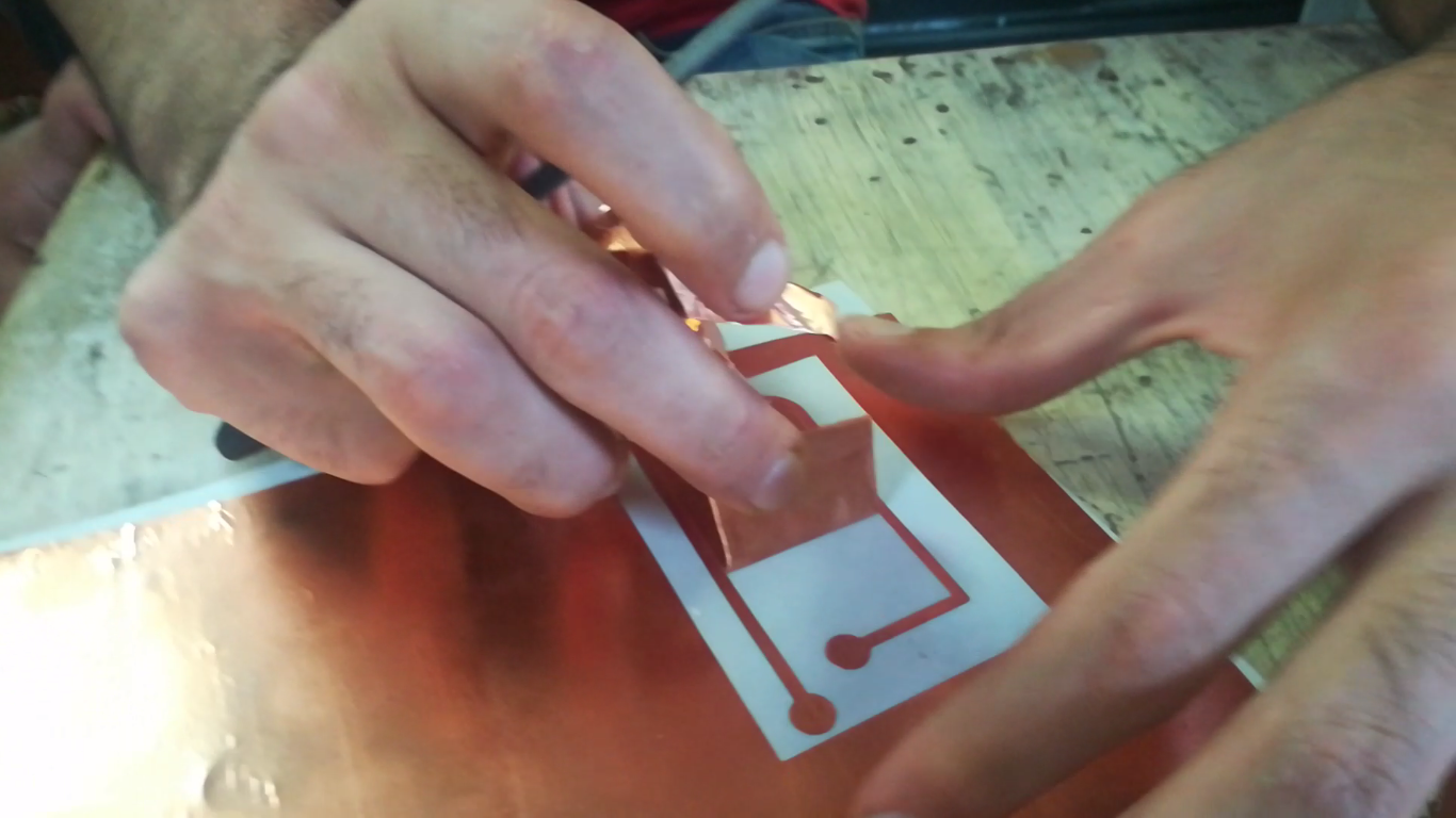
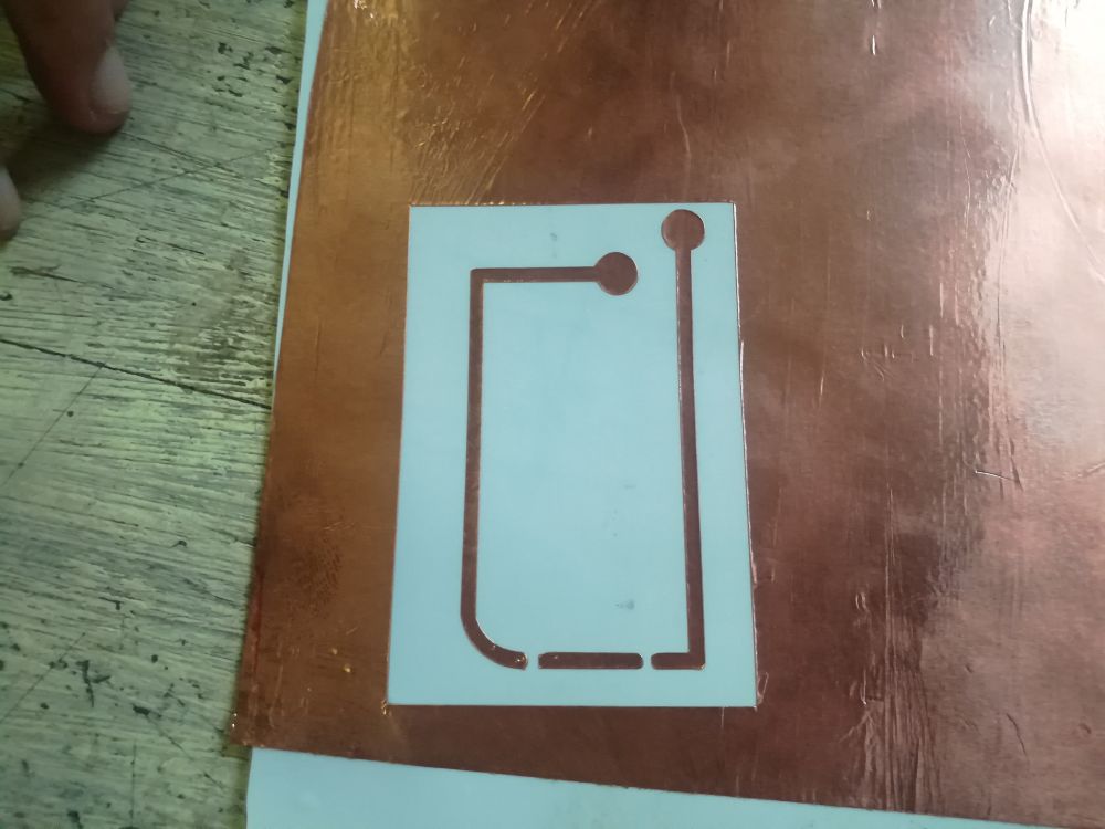
- Then, used masking tape to transfer the circuit to a piece of paper
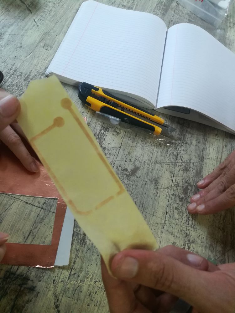
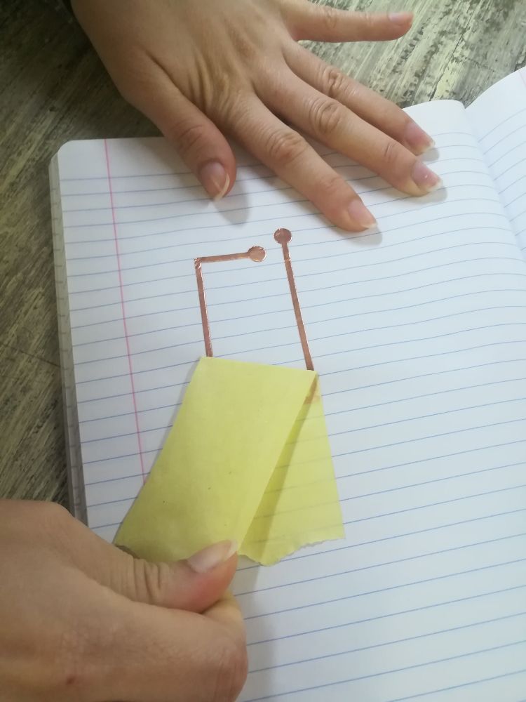
- Finally soldered the LED and resistor in place, and added a coin cell battery.
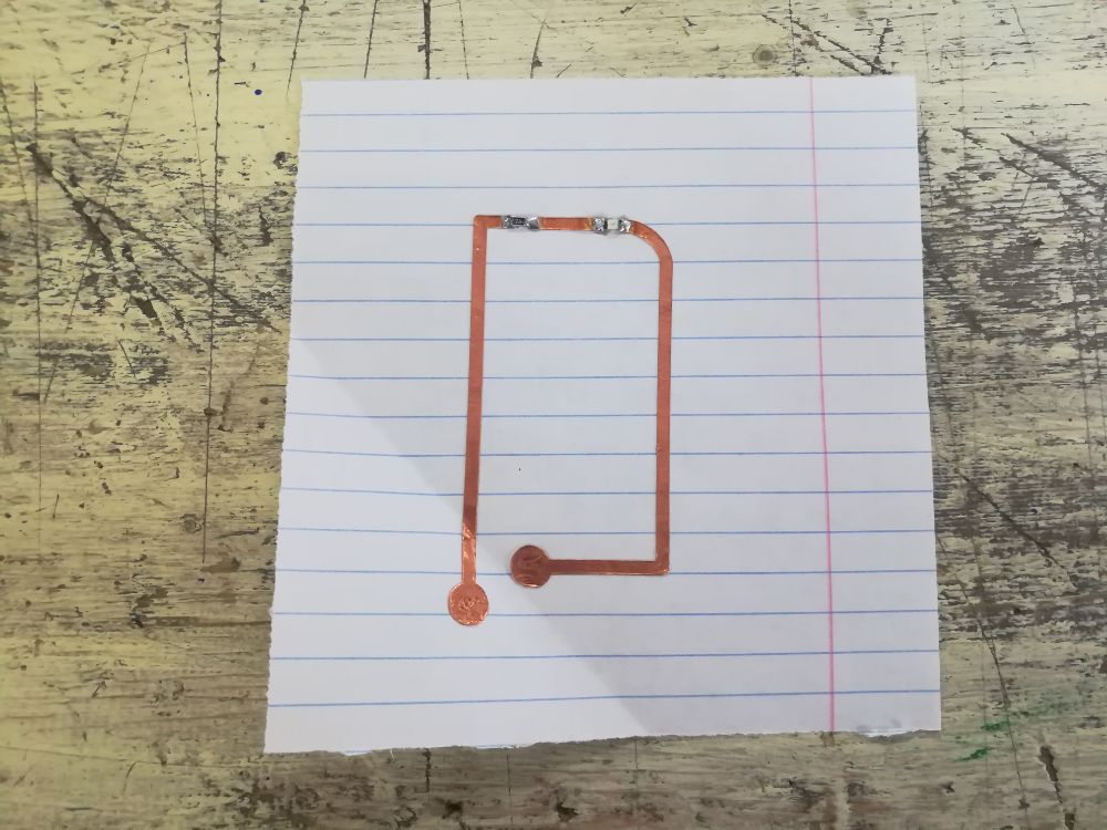
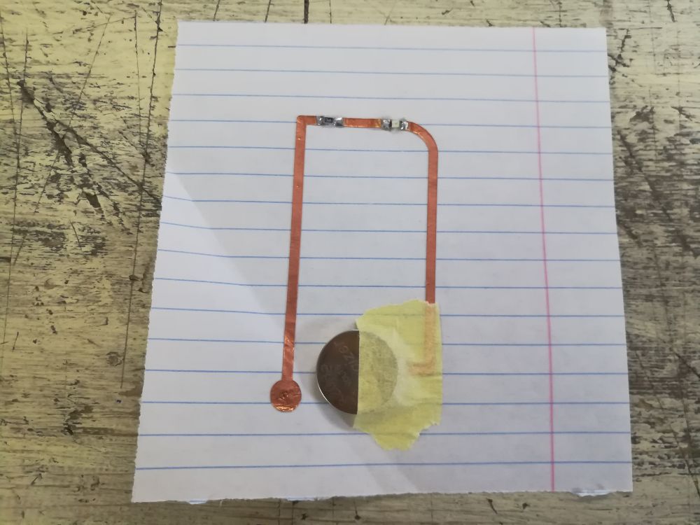
- And, it works nicely!
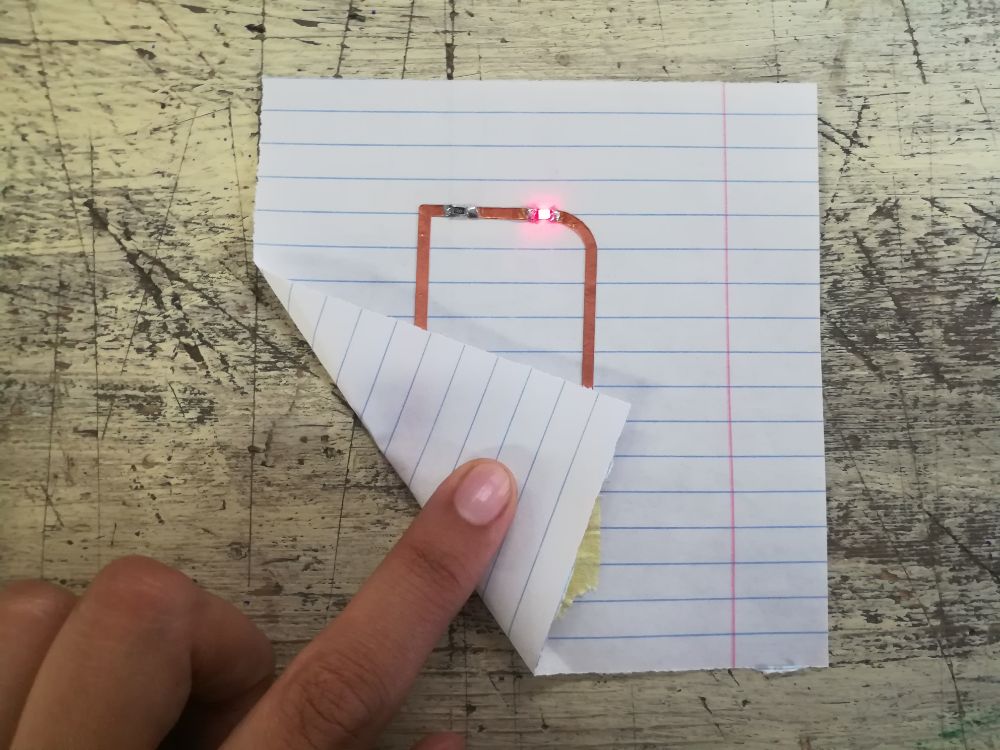
- Demo video:
Interactive Dandilion: Design
- After finishing experiments, I started designing my actual circuit for the week, an interactive circuit with an attiny45 processor that takes input from a microphone in the middle, and outputs a pattern of lighting with LEDs.
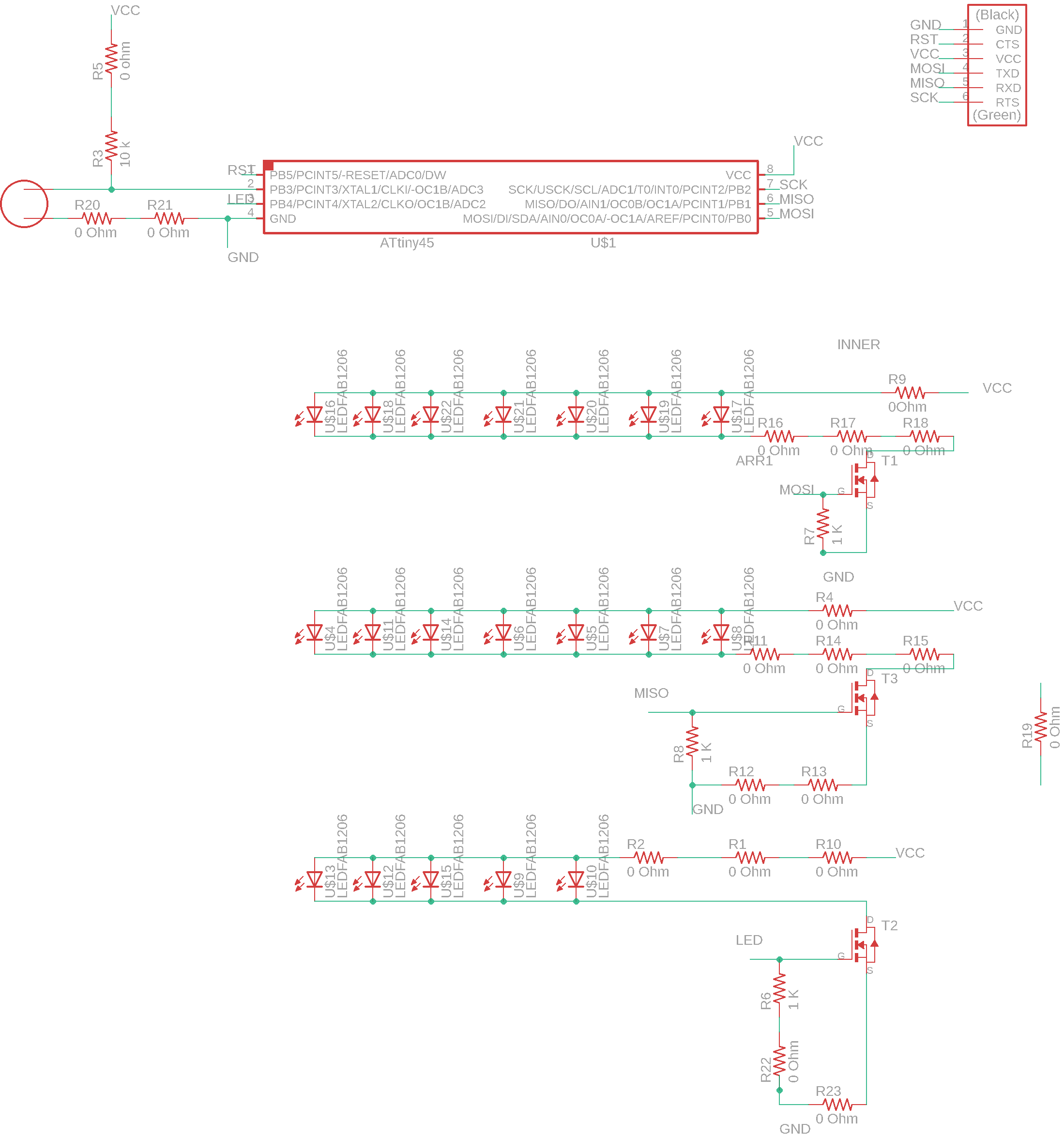
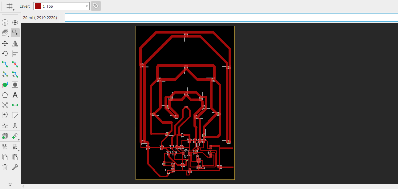
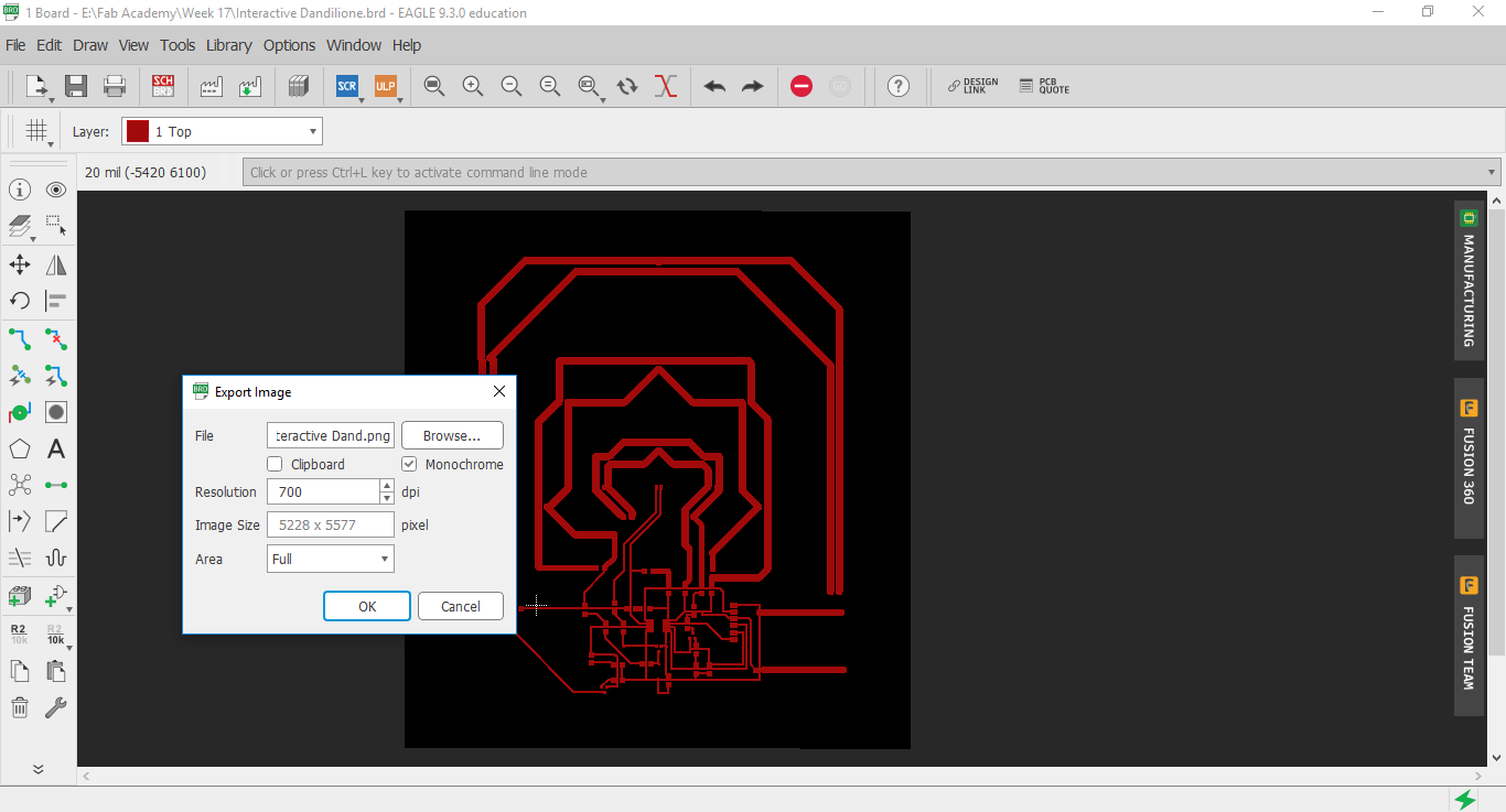
- After finishing the design, I exported a black and white PNG image from Eagle.
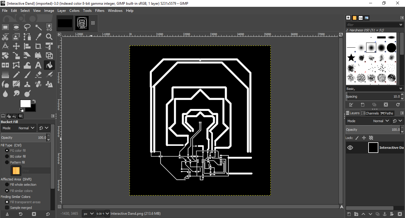
- Then, imported it in GIMP to export it into JPG format to be able to import afterwards into Cut Studio for fabrication.
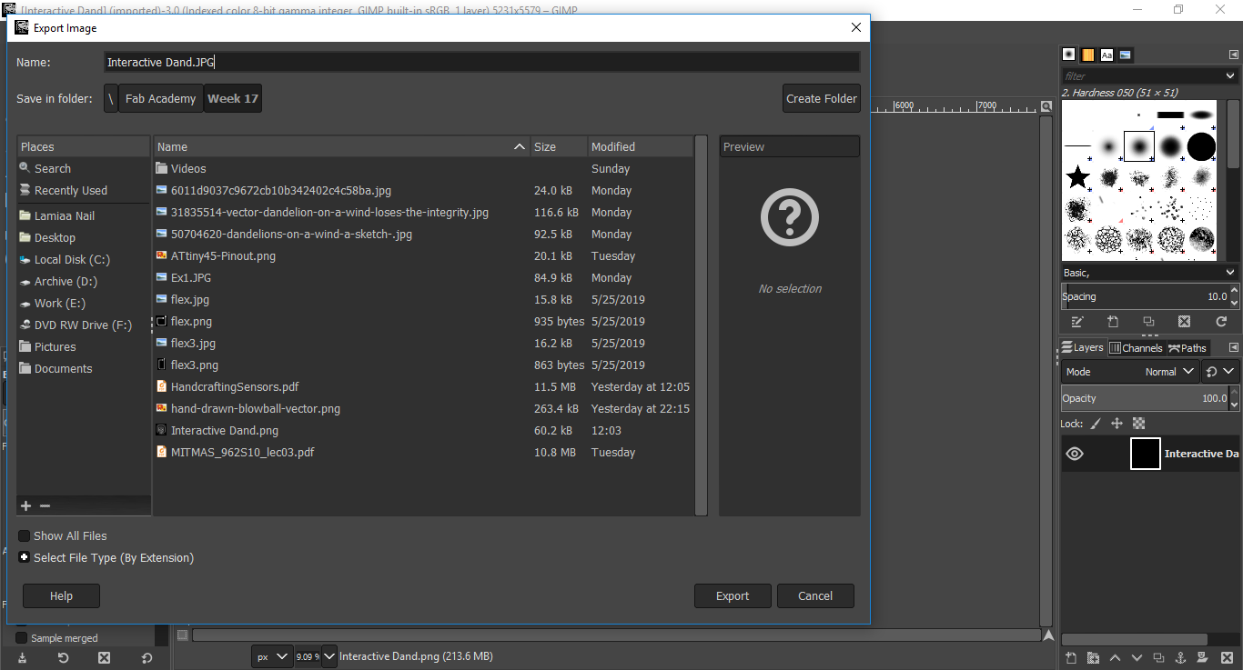
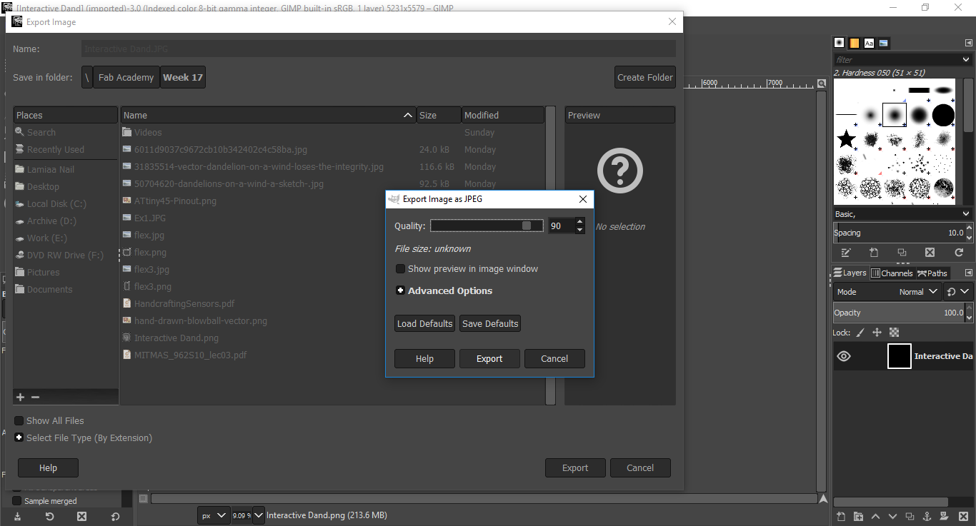
Interactive Dandilion: Fabriction
- I exported the JPG image into CutStudio
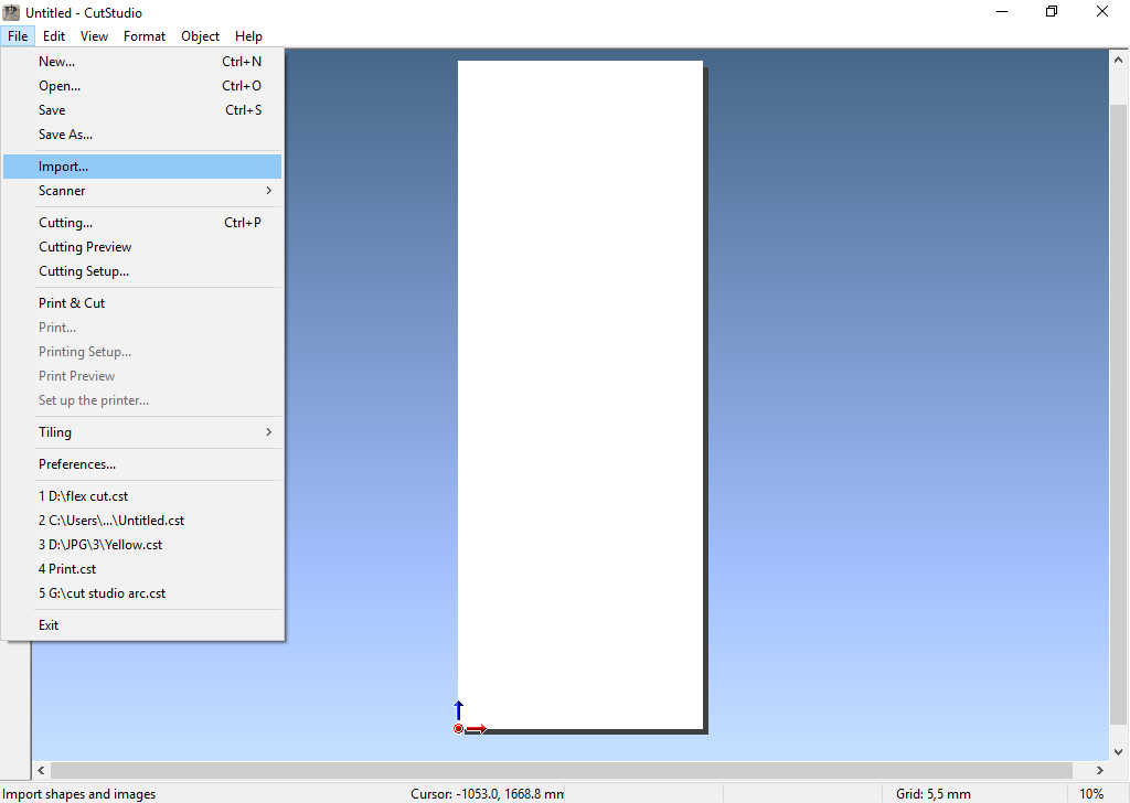
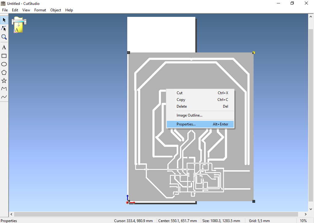
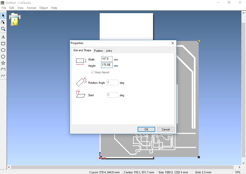
- I then navigated into Properties, to set the actual dimensions of the circuit.
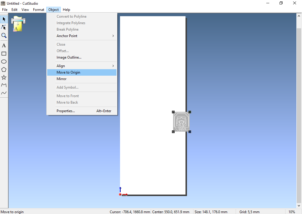
- Then move it to the origin
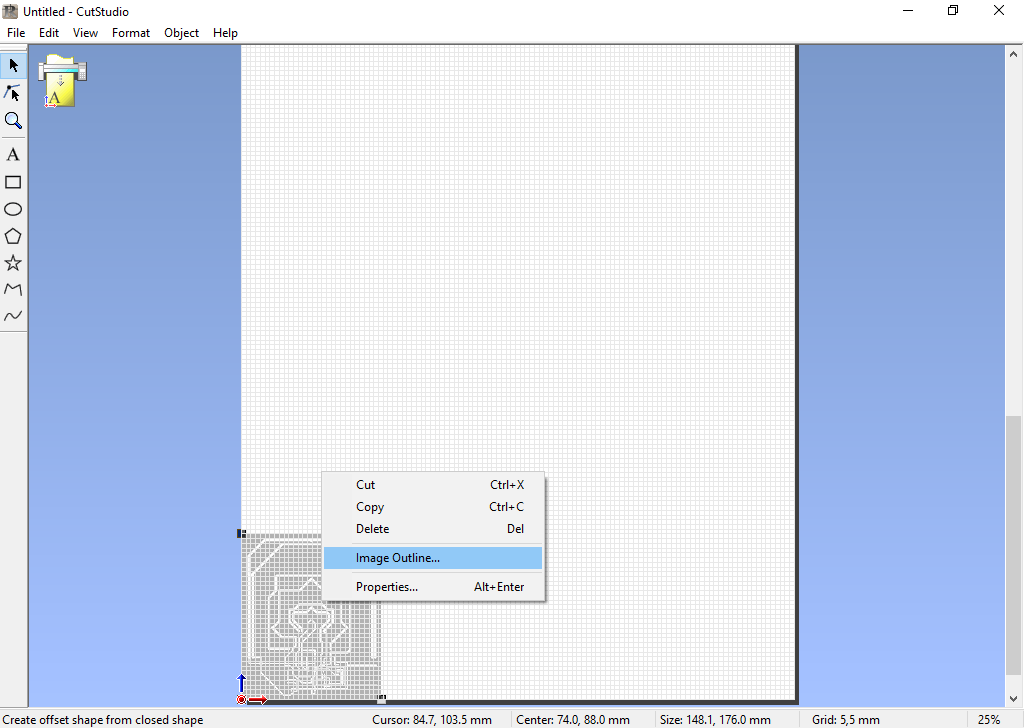
- Now, I needed to extract the outline that defines the toolpath for the Vinyl.
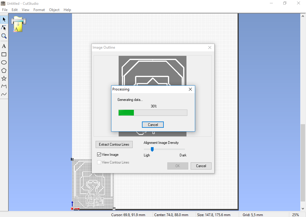
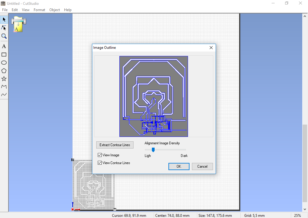
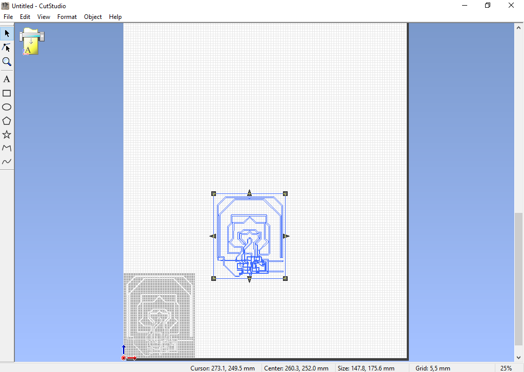
- Click extract contour line, move the contour away from the original image, delete the original image, and move the countour back to the origin.
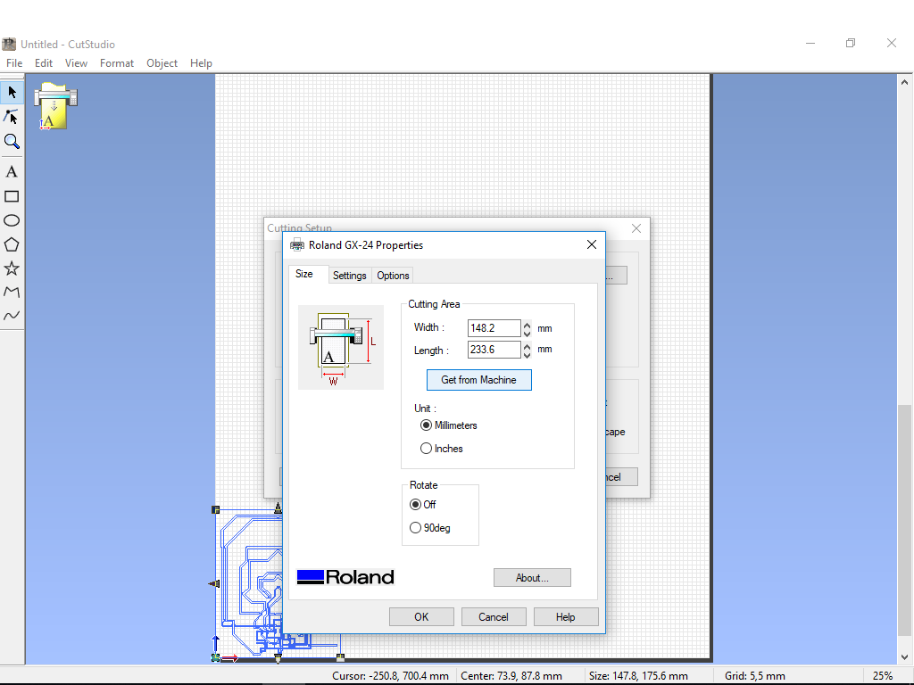
- Now, set the cutting area as measured by the machine
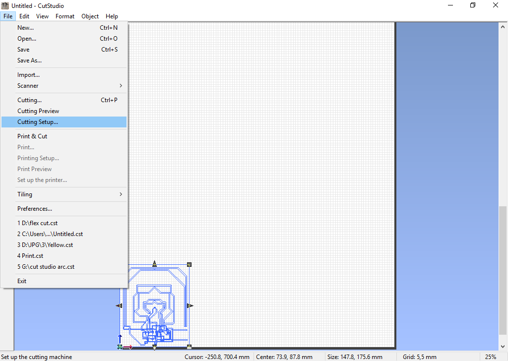
- Now, the circuit is ready for cutting!
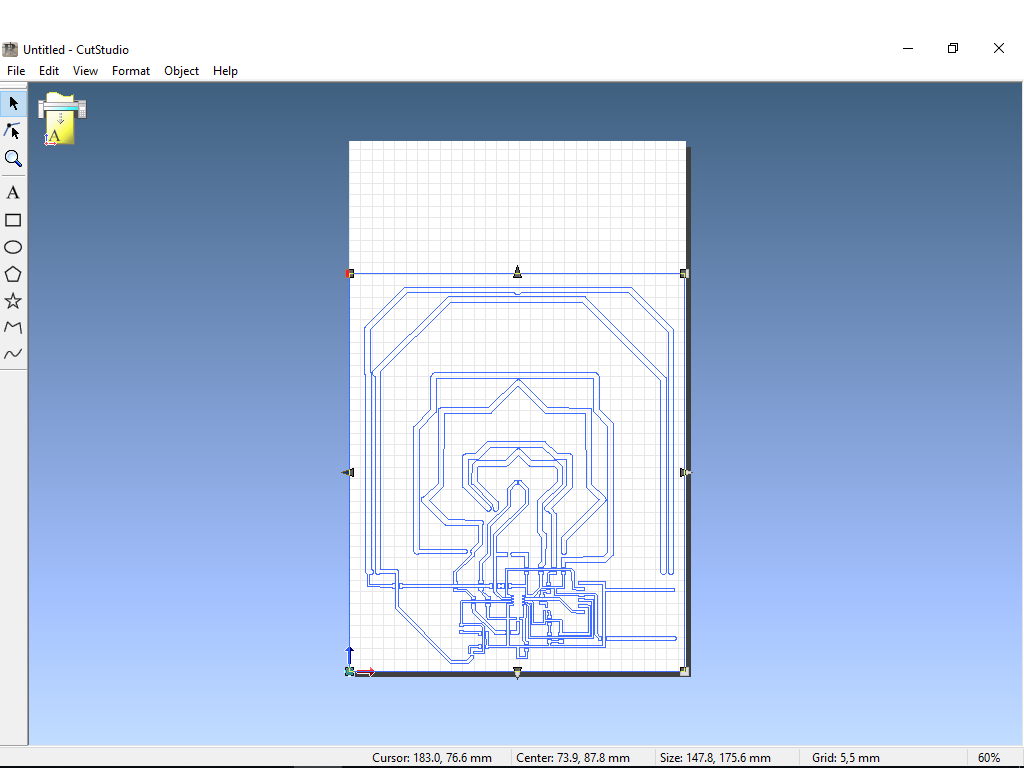
Failed Trial
- The first two trials where not successful. In the design, I set the traces width to 16, especially at the attiny45 pins also in other places in the circuit. These narrow traces where ripped out by the machine while cutting.
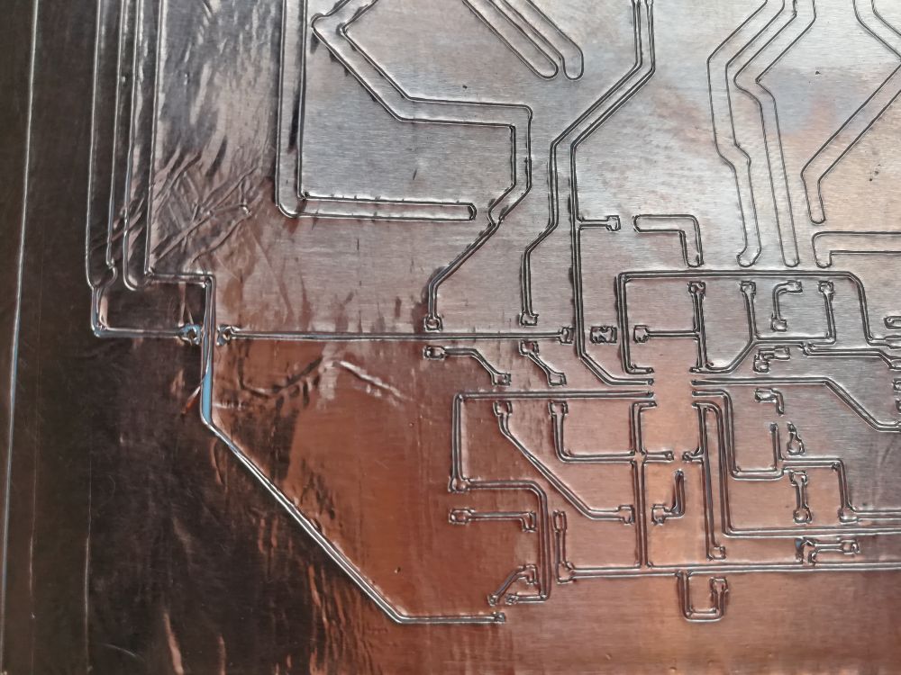
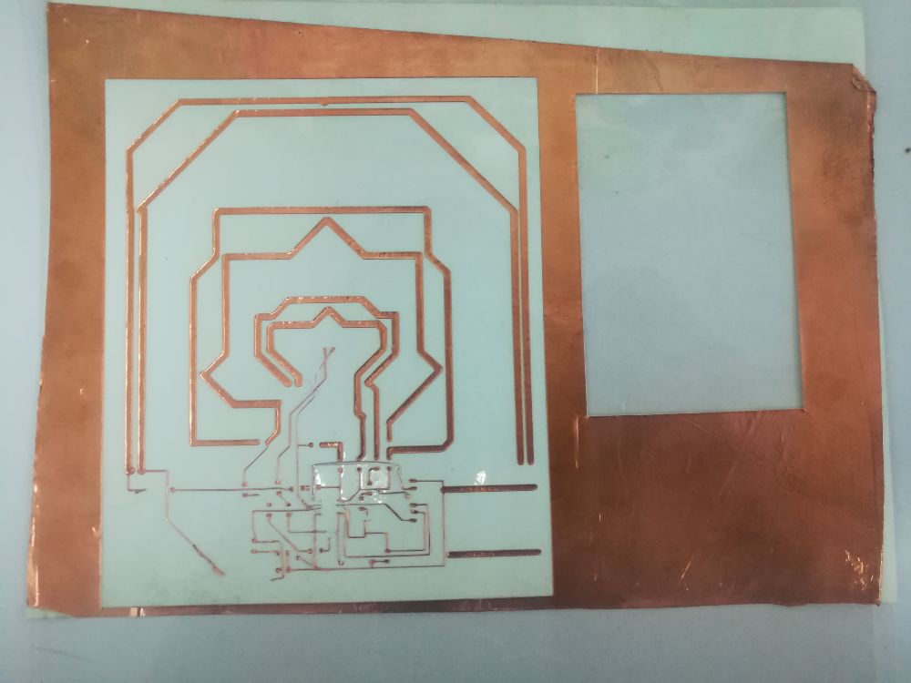
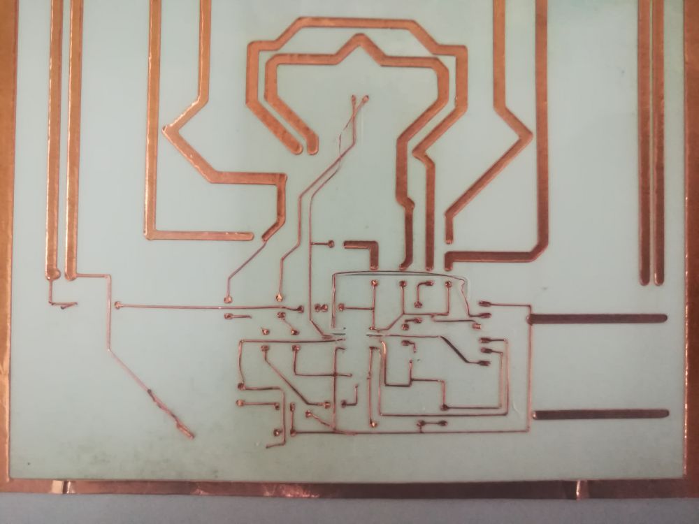
Successful Trial
- My approach to solve this problem was to increase the traces width as much as I can minimum at 24, and maximum at 100.. Second, is to decrease the cutting force from 200 to 100 gf to minimize the ripping.
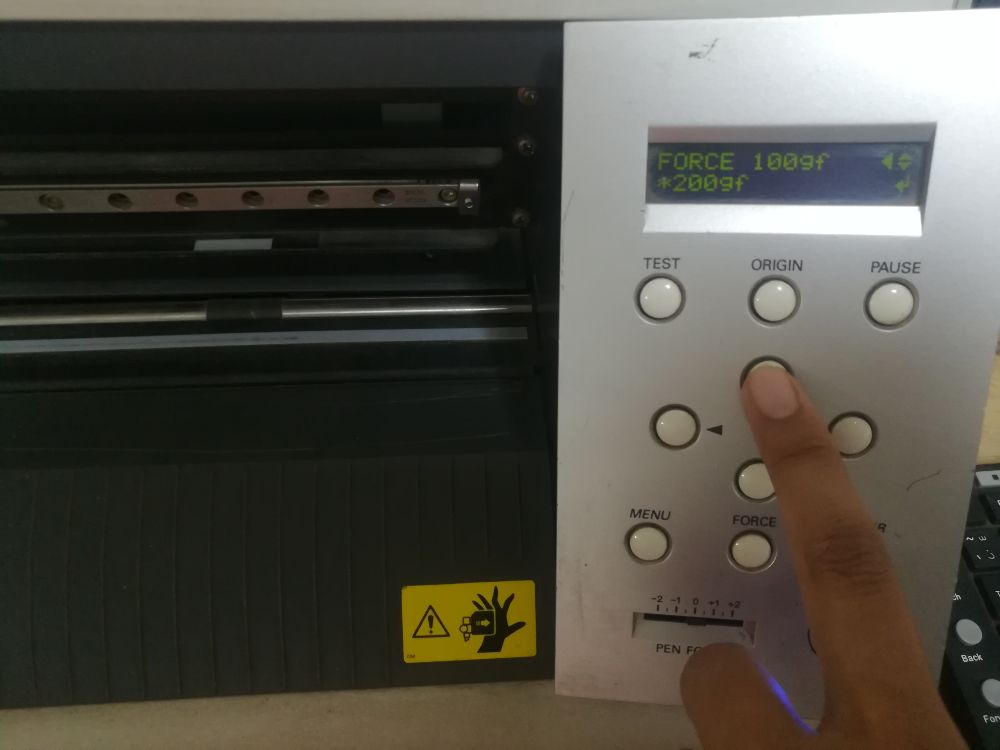
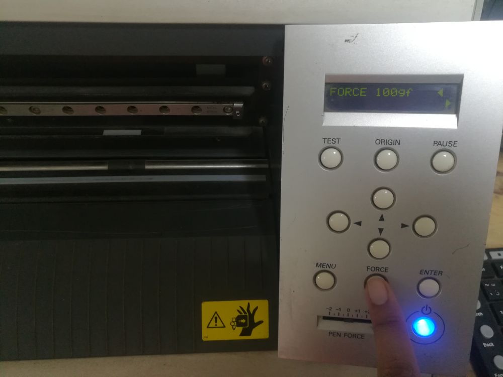
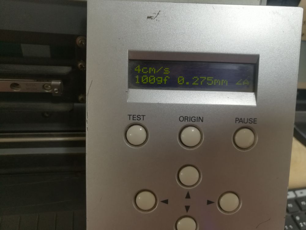
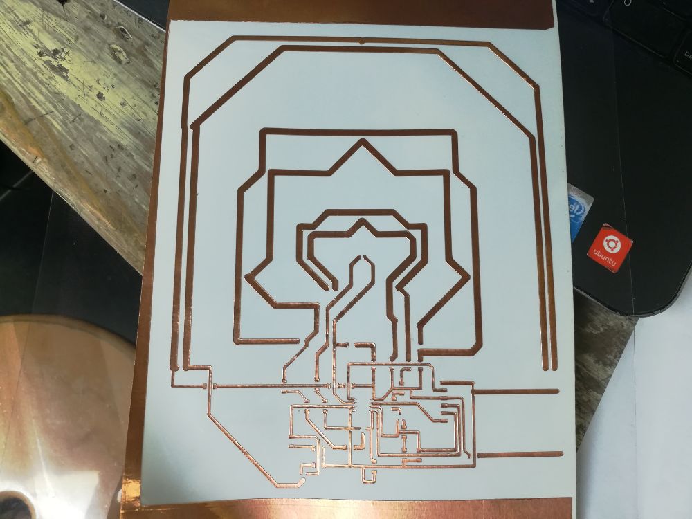
- The prototype was cut very nicely, without any ripping in the traces.
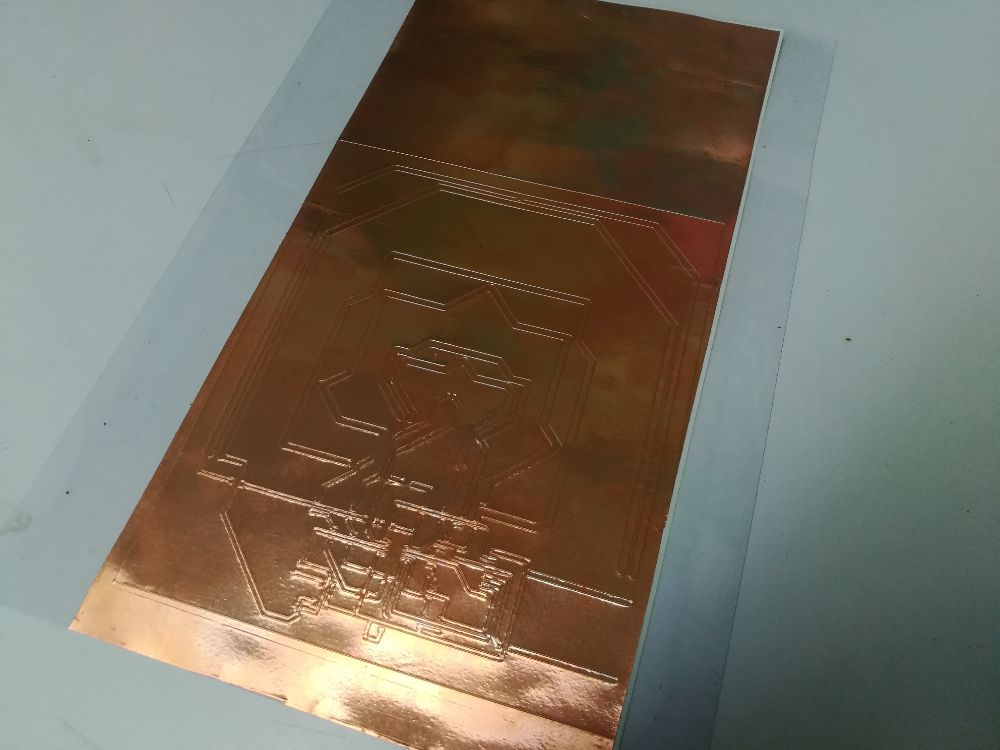
- And the flexible circuit is done!
Project 2: Screen Printing
- The second idea for the wildcard week was originally suggested by Ohad, our regional Guru. The idea was to screen print on fabric. It seemed like a simple idea, which my classmate Nada and I decided to pursue, however, we faced a road block as we didn't have the know how of the process or access to a person who had it, so we gave up on the idea.
- A second chance was presented to us during the Fab 15 conference, in the form of a workshop titled "[Easy] Screenprinting", by Ana Cabral. So, we decided to make a late wildcard week project out of it!
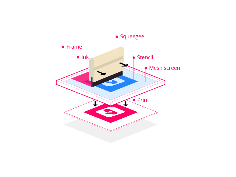
- What is screen printing?: it is the process of transferring an image design to a flat surface through a mesh screen.
- I didn't expect the process to be that easy and simple! The process consists of 4 steps: 1. Design and screen preparation, 2. Printing paste preparation, 3. Printing, and 4. Drying.
Step 1: Design and screen preparation
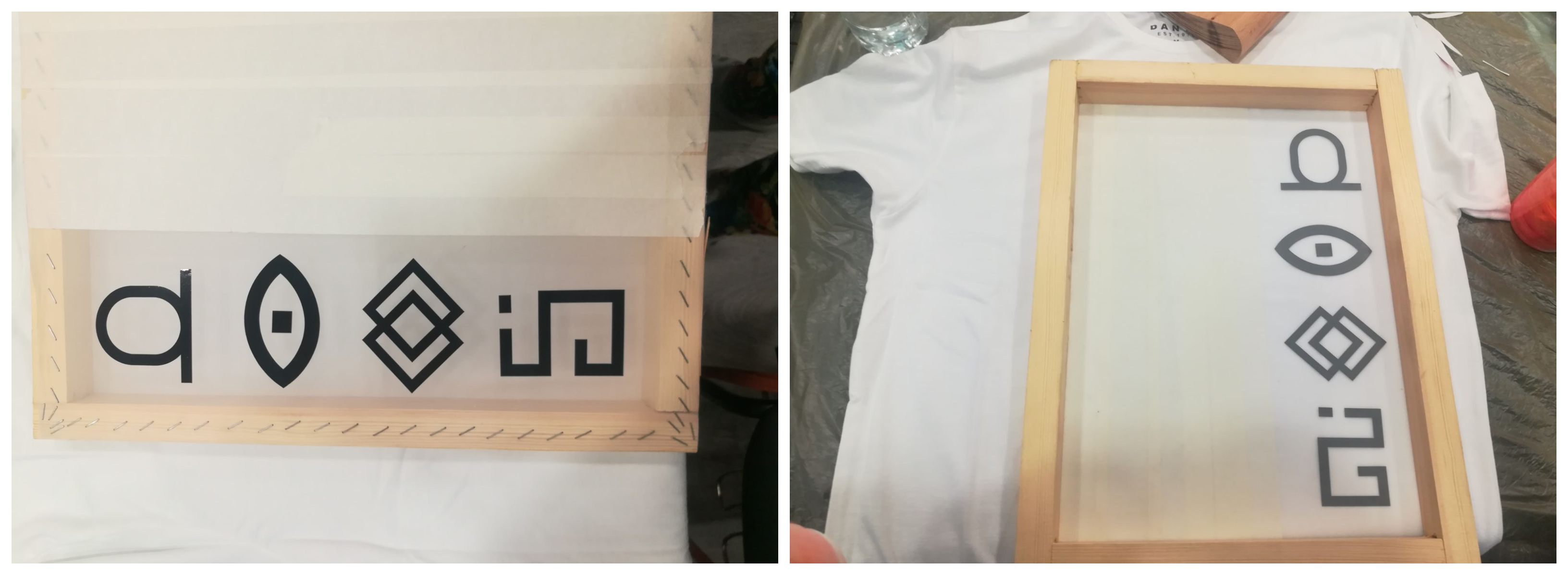
- For this project, I used a pre-prepared design, which was 4 different hieroglyphic symbols from the Fab 15 conference's brand design. But if I were to make my own design, I would probably use Inkscape software, check Computer-Aided Design Week for more details about how I used Inkscape to create 2D designs.
- The next step is create a stencil of the design. The stencil is basically a thin sheet of material with a shape or pattern taken out of it. The stencil material is Vinyl, which can be cut into the desired shape or pattern using the Vinyl Cutting machine, check computer-controlled cutting week for details on how to produce Vinyl cut images using the machine.
- I didn't actually use the stencil, I used the cut out of the stencil! I used the symbols themselves which means that the print will be the "negative" image of the symbol (more details on this later).
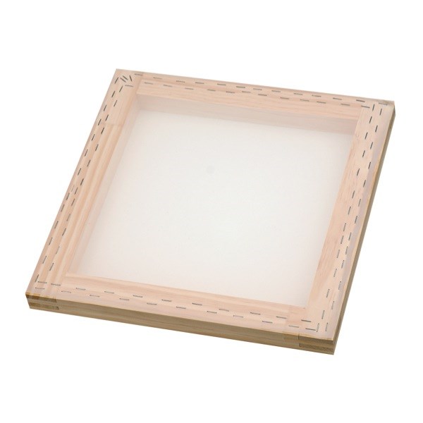
- Now that the design is ready, I bring the screen. The silk screen is a wooden frame with a layer of porus silk stretched over the top and fixed to the frame with a stabbler.
- I put the frame with the screen facing up, I laid the Vinyl symbols in a vertical pattern (photo below). I wanted to limit the printing area to the a rectangular shape around the symbols, so I covered the rest of the screen with a masking tape to keep the paint from transferring to the fabric in undesired areas.
- Finally, I flipped the frame so that the screen is face down, in direct touch with the fabric of the t-shirt.
Step 2: Printing paste preparation
- Now we need to prepare the paste that will be applied to the t-shirt. This paste is prepared from three main components: white printing paste, pigment color(s), and a binder.

- The commercially available printing materials in Egypt come with no label! Which makes it hard to find it's datasheet to look up the mixing ratios. For exact ratios and datasheets, please contact the workshop instructor: Ana Cabral.
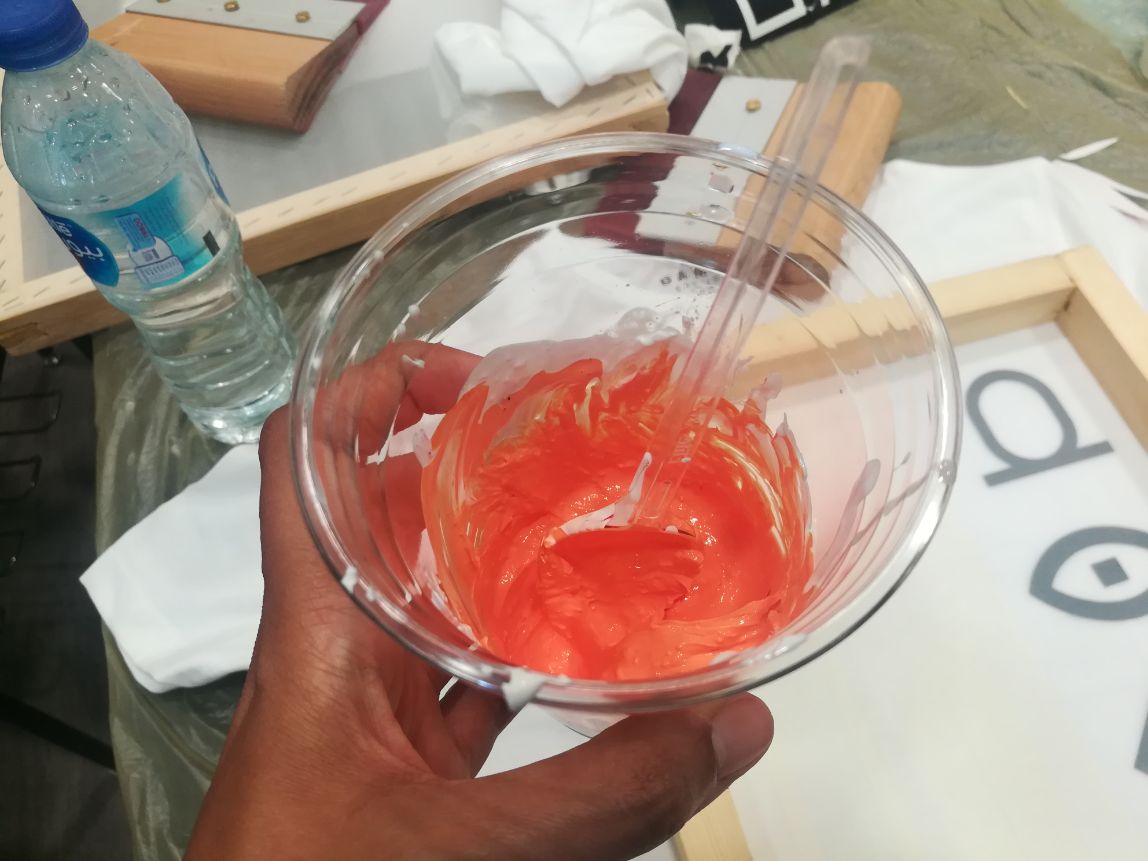
- In this case, we turn to trial and error until reaching the right mix. I Brought a plastic cup and a plastic spoon, I filled around 2 full spoons of the white paste, then around 1/4 spoon of the red pigment and the same amount of the yellow pigment and mixed them all together, and the result was a kind of a orange/simon color.
- I finally added around 1/2 spoon of the binder to the mix. The binder plays an essential role in the printing process, when the binder is heated it turns into a layer of "plastic", basically trapping the pigment between the fabric surface and the plastic layer, so it doesn't go off with washing.
- And now the paste was ready for printing!
Step 3: Printing
- NOTICE! before applying the paste on the screen, make sure to put a piece of paper between the t-shirt sides (front and back), to make sure that the pigment will only transfer to the desired side.
- Use the mixing spoon to put the paste on the screen, and to spread it evenly on it we use a "squeege", a tool with a rubber blade that is used to control the flow of liquids.
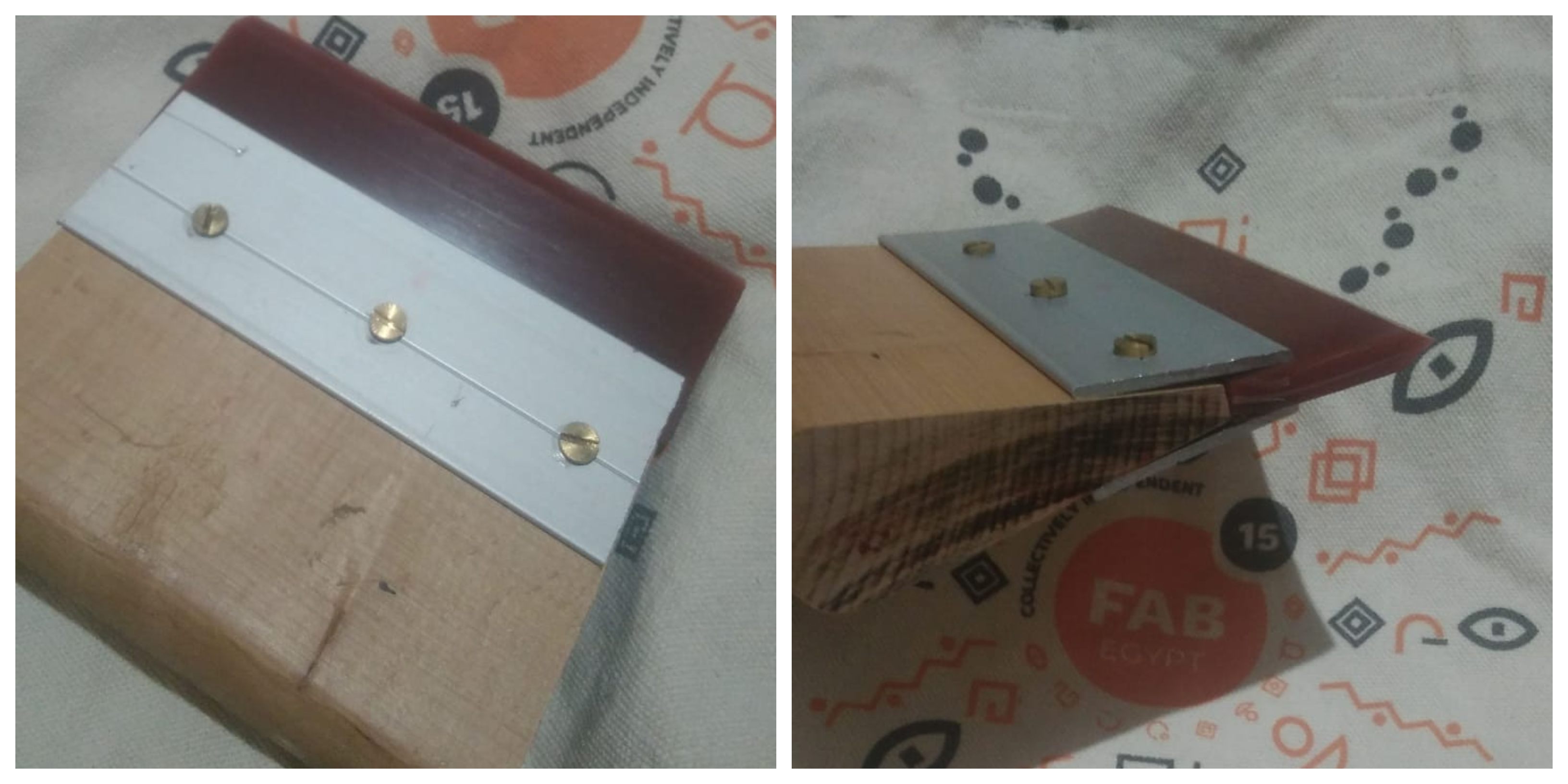
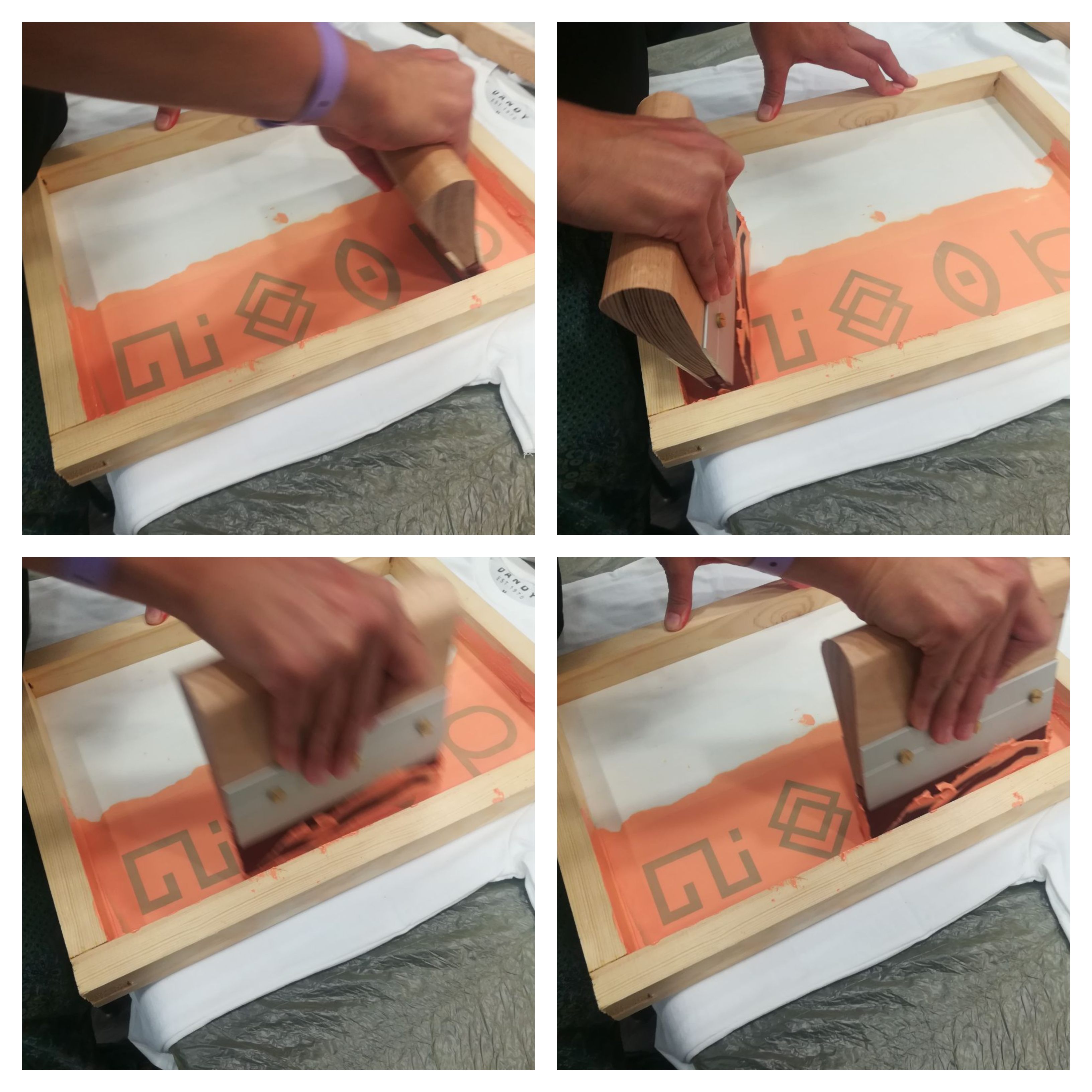
- Use the squeege to spread the paste, and remove the extra paste using the rubber blade.
- Now remove the frame carefully from the t-shirt surface and the printing is done!
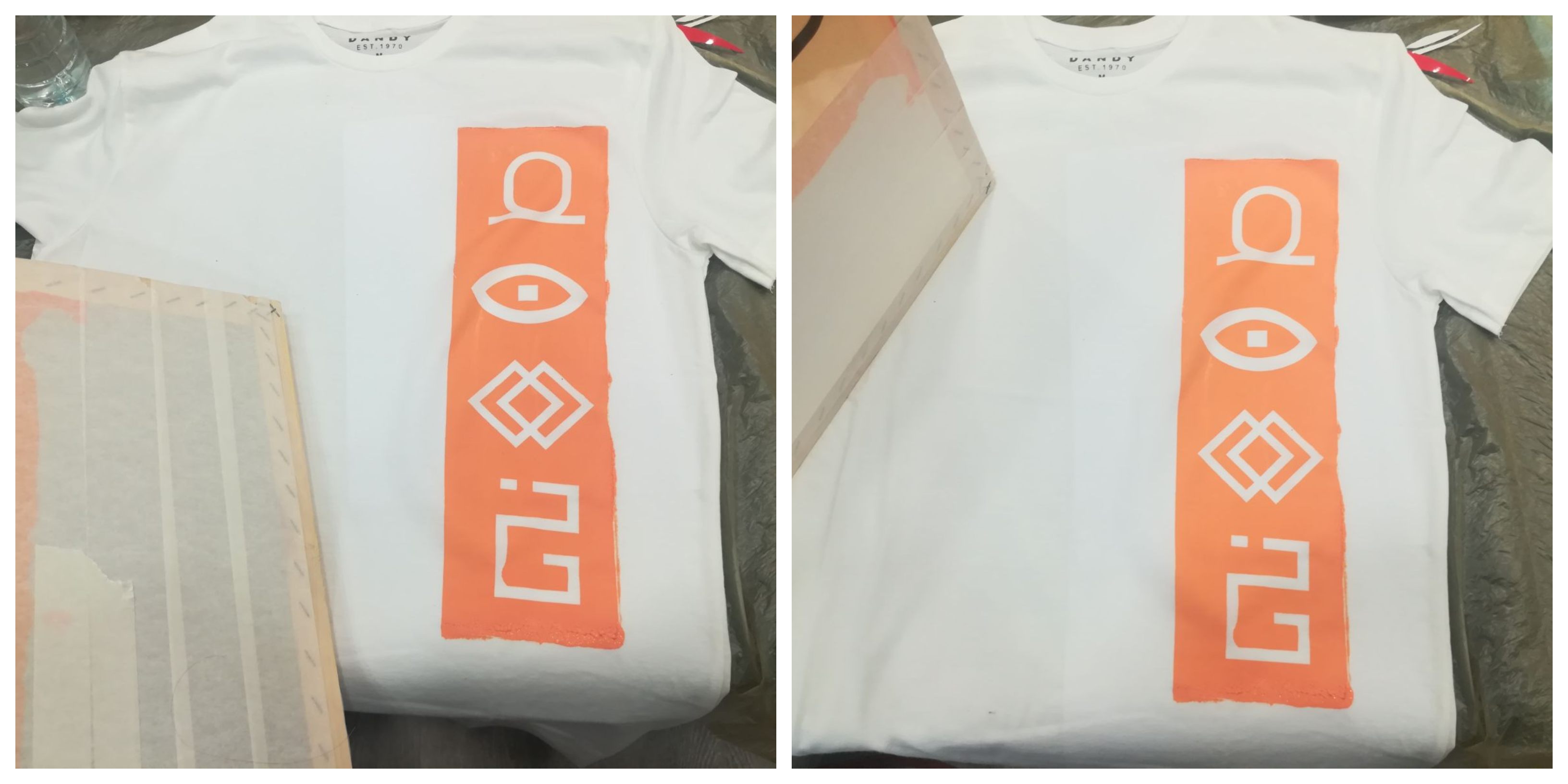
- As I mentioned earlier the final image is a "negative" image. The whole area around the symbols is colored except for the symbols area.
Step 4: Drying
- The drying step is very essential as I mentioned earlier. The drying can be achieved by either leaving the t-shirt just to dry in room temperture which is relatively high in summer days and nights in Egypt!
- Or for quick results, I used a heating press machine. I laid down the t-shirt inside the heating press, set the temperture at 120 degrees for 10 seconds and the drying was done.
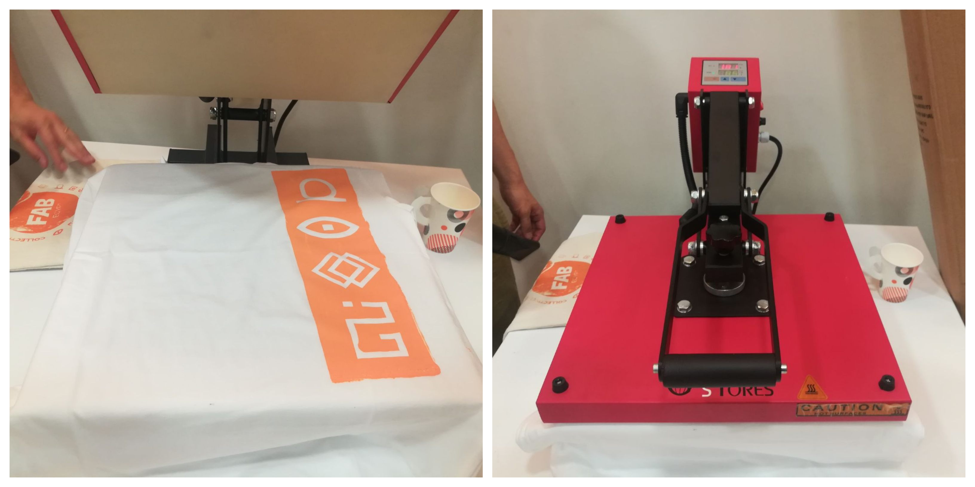
- The end result was amazing, to the extent that other people in the workshop borrowed my screen frame to make their own t-shirts! This is one of the advantages of screen printing, it can be used to reproduce a design multiple times easily.
Design Files