Final Project: "Xpresso" Robotic Head For kids with Autism
Background & Concept
- Autistic kids are characterized with facial expressions recognition impairment, they can't simply infer from a person's face if s/he is happy, angry or sad.
- Researchers have been tinkering around with using robots instead of human therapists with autistic kids, and they found very positive engagement with robots. Autistic kids find it easier to interact with robots than humans because their reactions and expressions are simpler, consistent and less overwhelming.
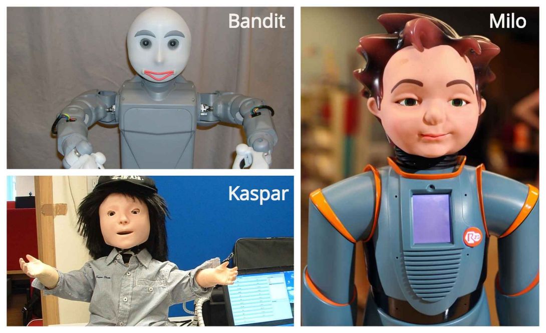
- Milo , Bandit , and Kaspar to name a few, are social robots which were developed with a wide range of interactive abilities, starting from expressing basic emotions, up to talking, dancing and playing games. These capabilities have proven to be useful in developing social interaction skills in children with autism.
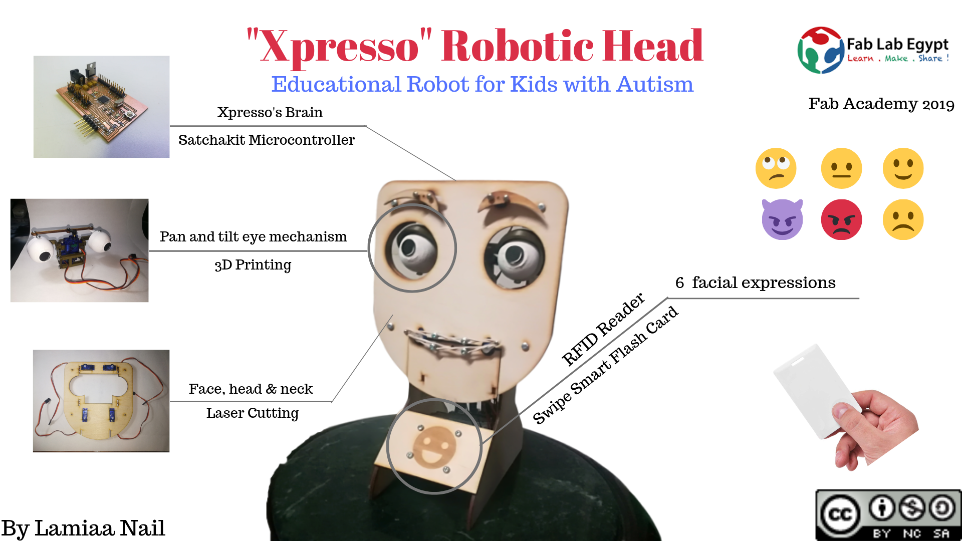
- For my Fab Academy final project, I developed "Xpresso", an expressive educational robotic head for children with autism. This robotic companion will serve as "facial expressions live guide". Kids can use it to learn various facial expressions.
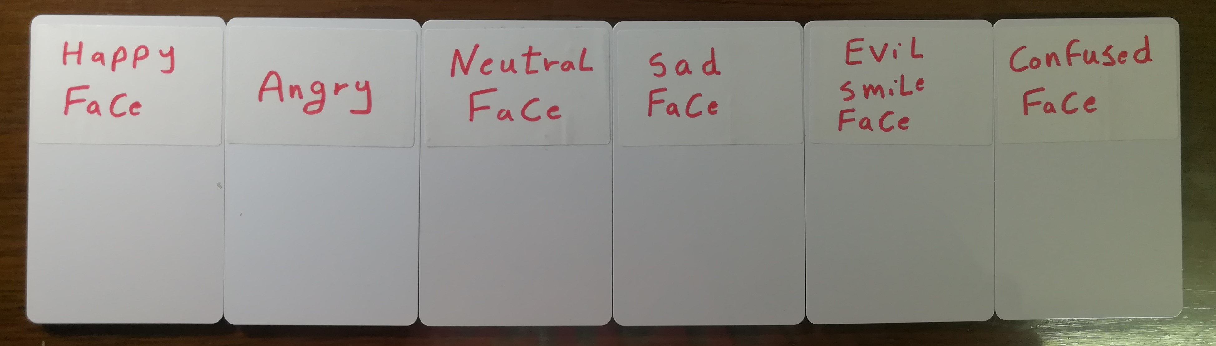
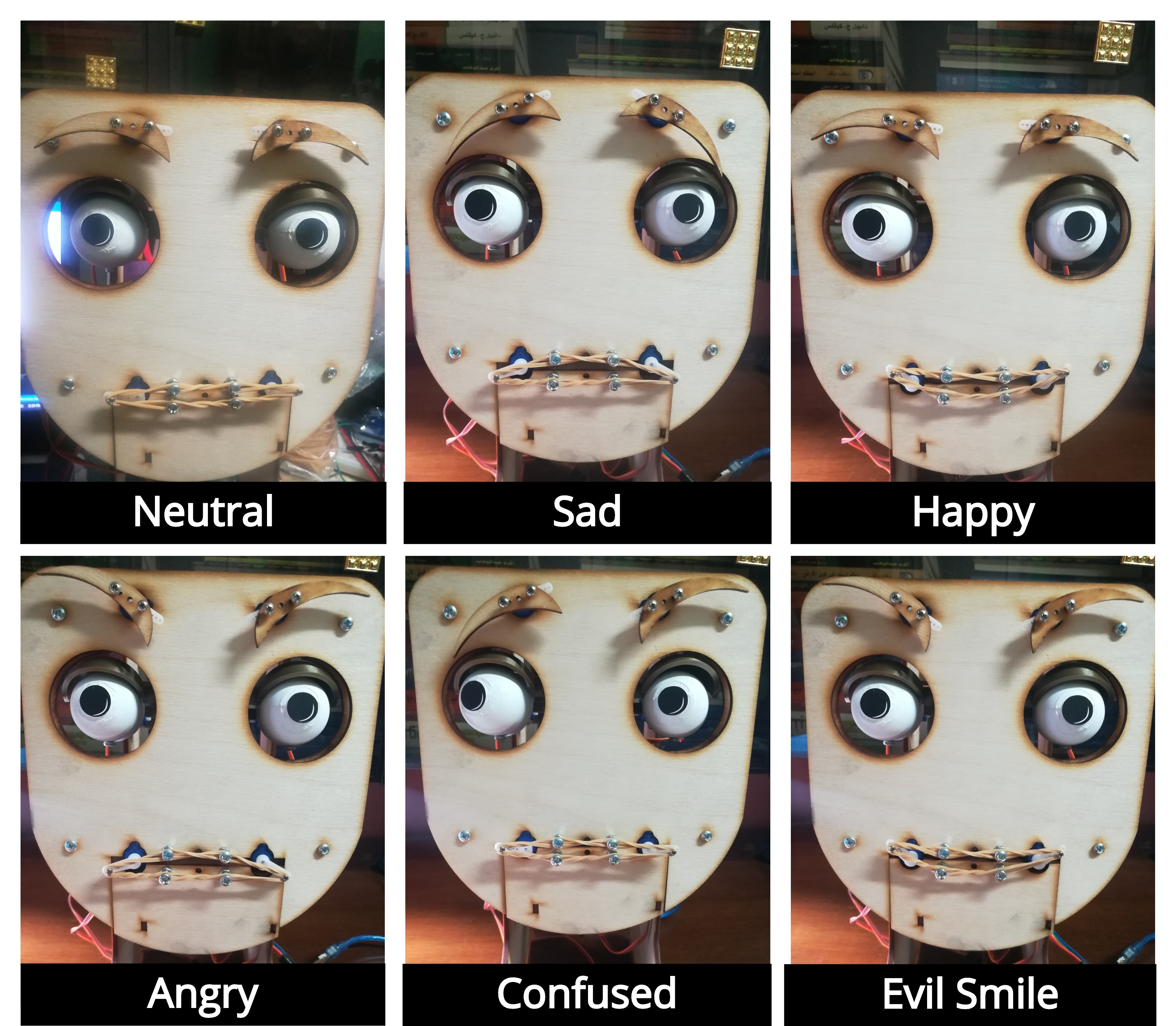
- How it works: A smart flash card is scanned on the robot's front panel to elicit pre-programmed facial expressions from the robot. Each card is unique and can elicit only one of six simple expressions: happy, sad, angry, confused, evil smile and neutral, to help the child learn to recognize human facial expressions.
- To develop my final project I used the digital fabrication techniques that I learned throughout my 6 months in Fab Academy: 2D and 3D design for the chassis and mechanisms of the robot, electronics design and productions for the robot's microcontroller, laser cutting for the robot's face, head and neck, 3D printing for the robot's eyes' pan and tilt mechanism parts, and embedded programming to bring the robot's facial expressions to life using RFID tags.
Project Bill of Materials (BOM)
| No. | COMPONENT | AMOUNT | UNIT PRICE | TOTAL PRICE | VENDOR |
|---|---|---|---|---|---|
| 1 | Atmega328p | 1 | RAM(LOCAL SHOP) | ||
| 2 | Crystal 16Mhz/18pF | 1 | 0.25 USD | 1.5 USD | FARNELL |
| 3 | 22 pF Capacitor | 2 | FARNELL | ||
| 4 | 1 uF Capacitor | 1 | 0.05 USD | 0.4 USD | FARNELL |
| 5 | 499 Ohm Resistor | 2 | 0.05 USD | 0.05 USD | FARNELL |
| 6 | 100 nF Capacitor | 2 | 0.1 USD | 0.4 USD | Digi-Key |
| 7 | Push Button | 1 | Digi-Key | ||
| 8 | FTDI pin Header | 1 | 0.25 USD | 0.25 USD | FARNELL |
| 9 | Mifare MFRC522 13.56 RFID tag Reader | 1 | 8 USD | 8 USD | >RAM(LOCAL SHOP) |
| 10 | 9g Servo Motor (Micro) | 9 | 3.6 USD | 32 USD | RAM(LOCAL SHOP) |
| 11 | RFID Tags | 5 | 0.5 USD | 2.5 USD | RAM(LOCAL SHOP) |
| 12 | 3.3 v Volatge Regulator LM1117 | 1 | RAM(LOCAL SHOP) | ||
| 13 | 10 uF Capacitor | 4 | 0.7 USD | RAM(LOCAL SHOP) | |
| 14 | 2x3 SMD Pin Headers | 5 | RAM(LOCAL SHOP) | ||
| 15 | Power Jack | 1 | 0.2 USD | 0.2 USD | RAM(LOCAL SHOP) |
| 16 | Power adaptor | 1 | 2.8 USD | 2.8 USD | FARNELL |
| 17 | LEDs | 2 | FARNELL |
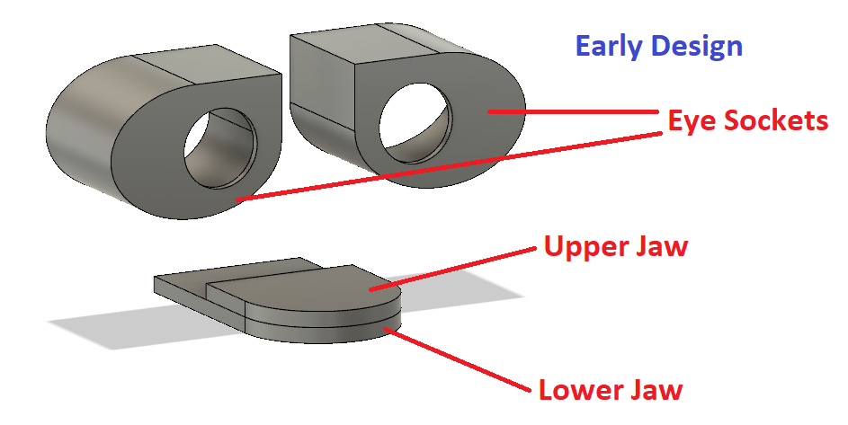
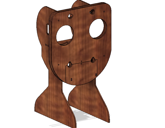
2D & 3D Design of Xpresso
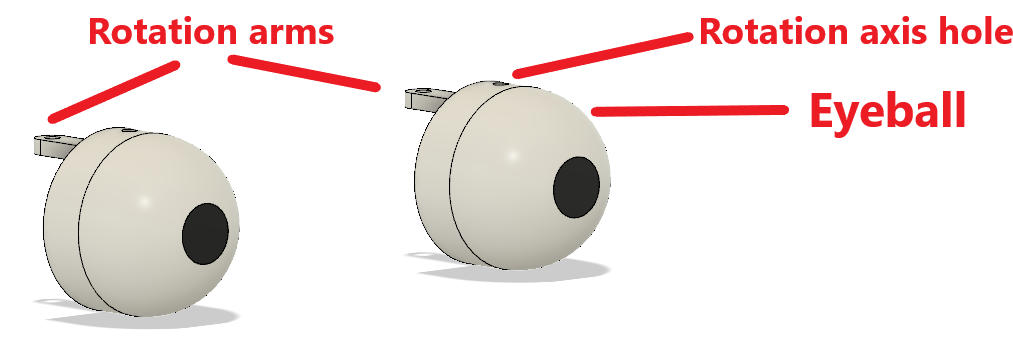
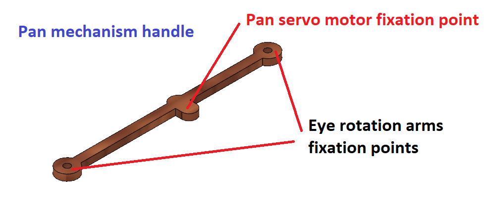
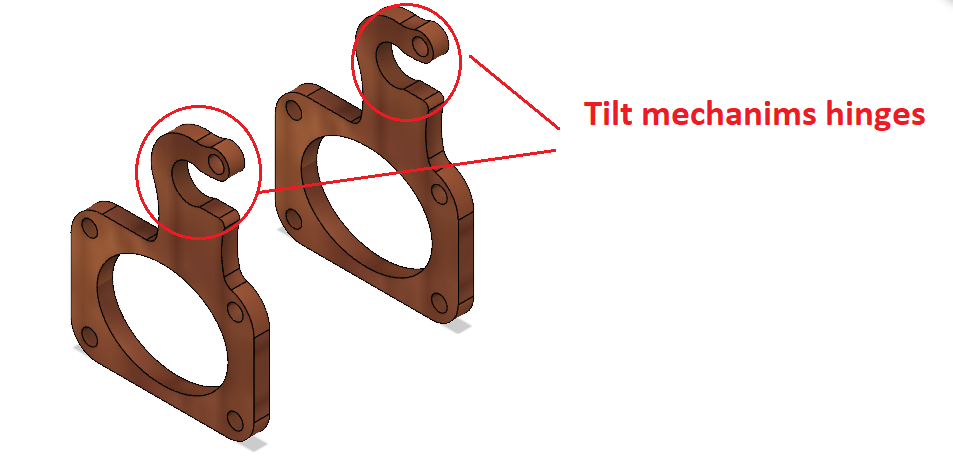
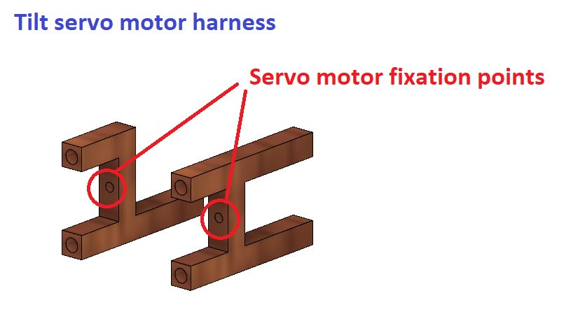
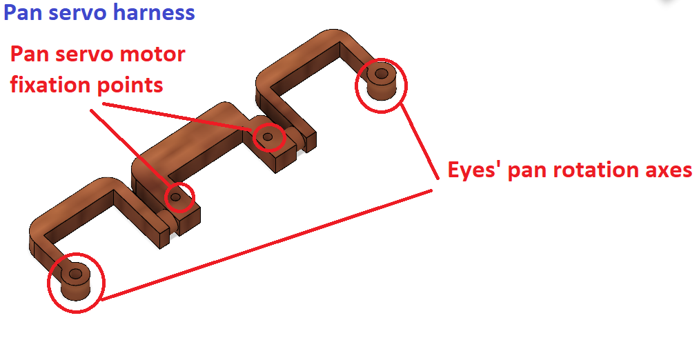
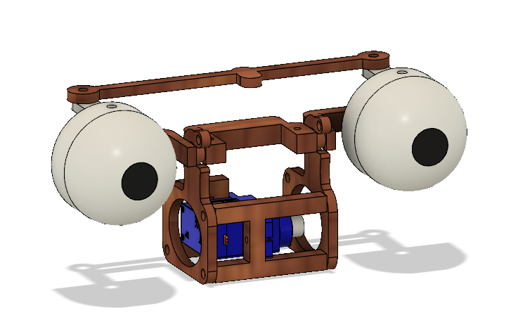
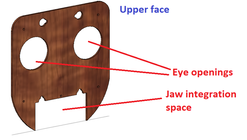
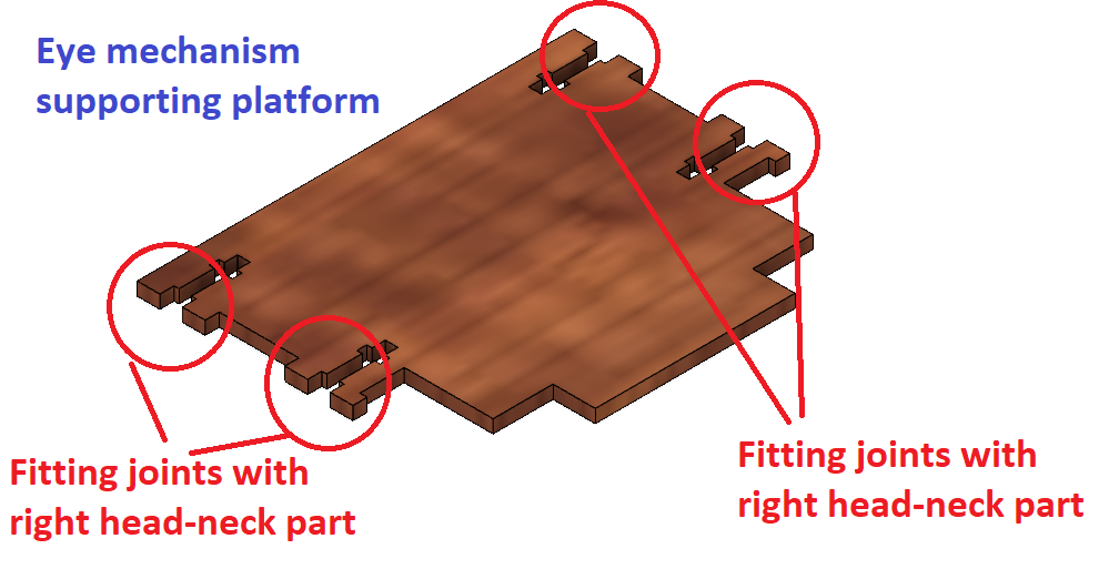
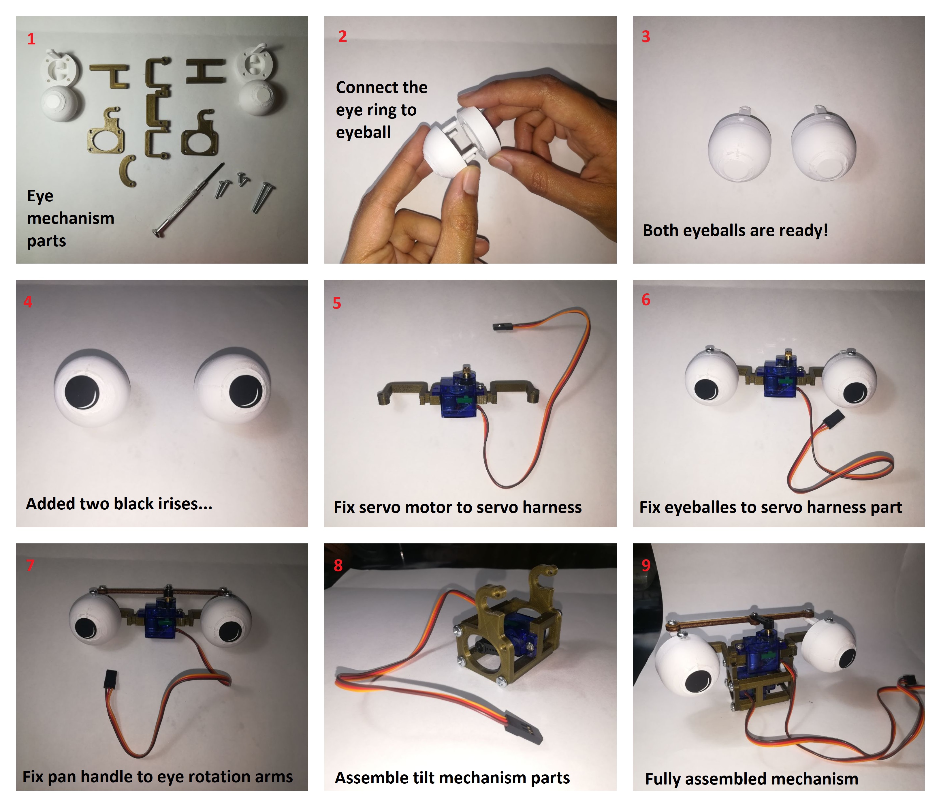
- Eyeballs Mechanism: tilt and pan movement
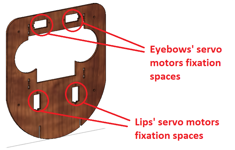
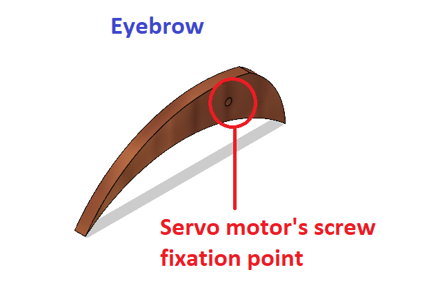
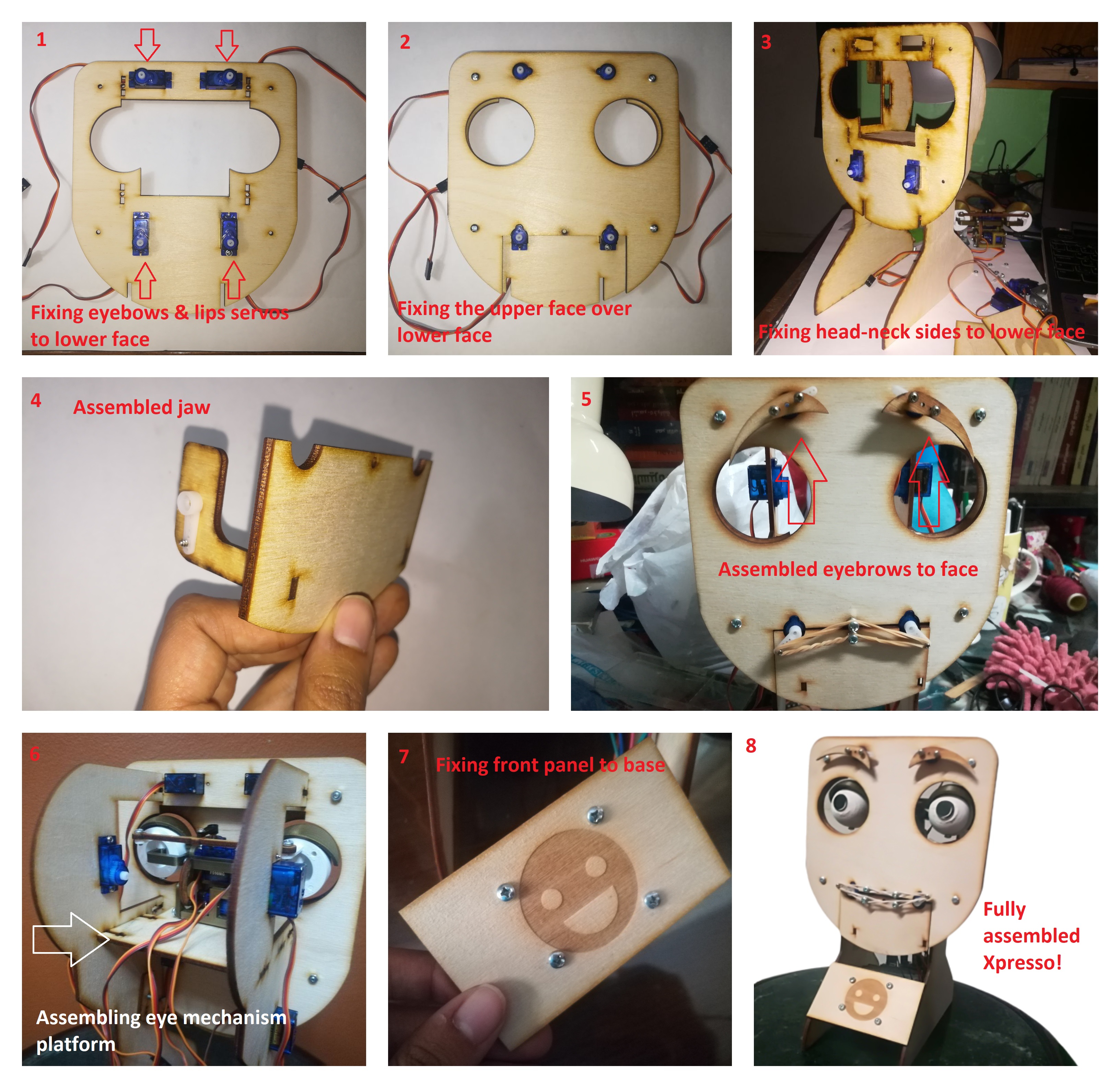
- Eyebrows Mechanism: Up and down movement
- Lips Mechanism: seperate right and left corners raise and lower movements
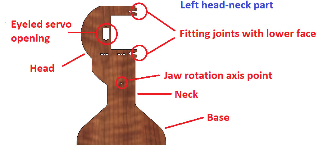
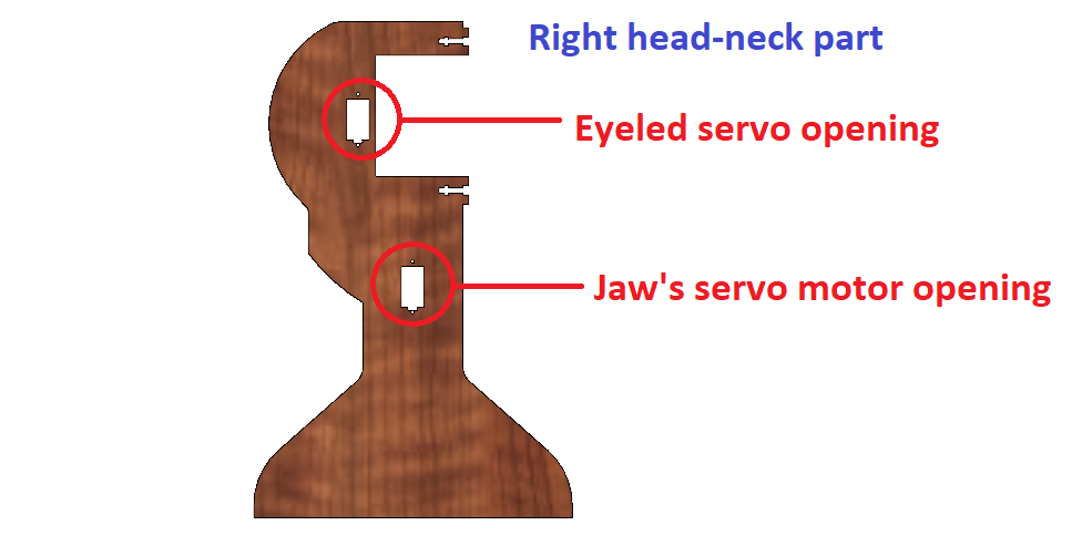
- Eyeleds Mechanism: up and down movement
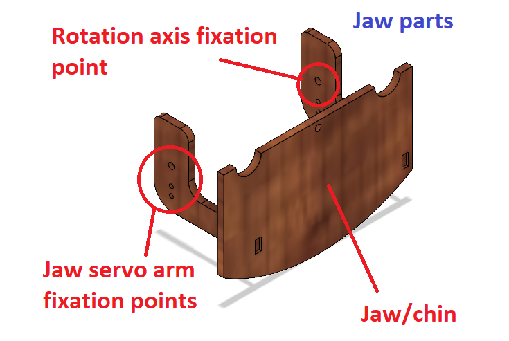
- Lower Jaw Mechanism: up and down movement
- Neck mechanism: pan and tilt movement
Fabrication Process
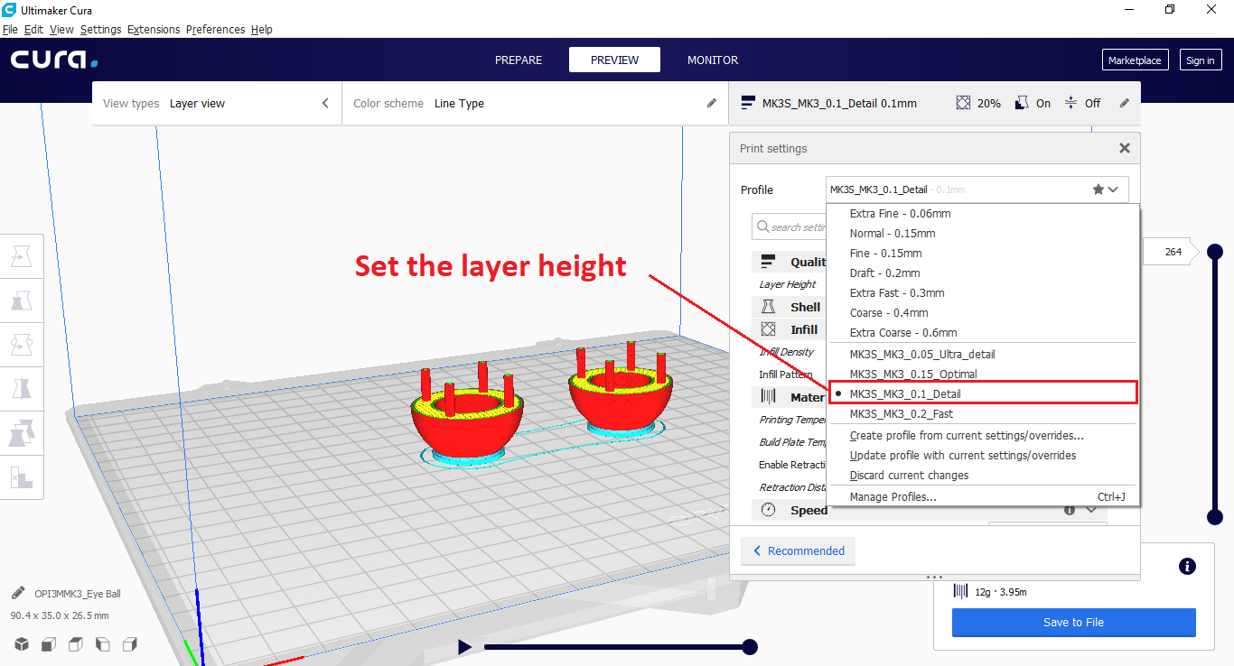
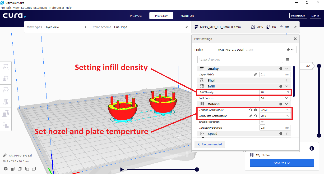
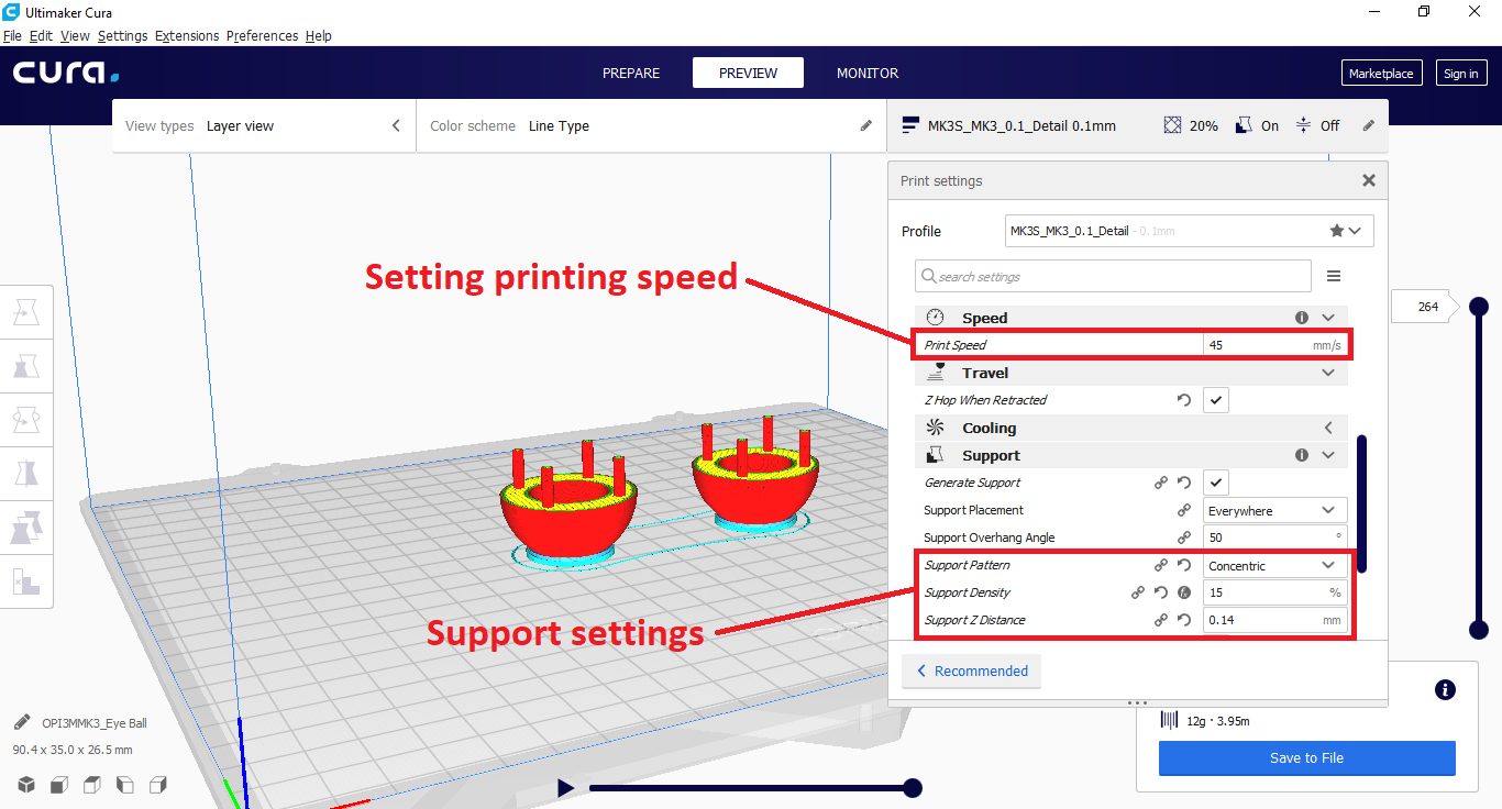
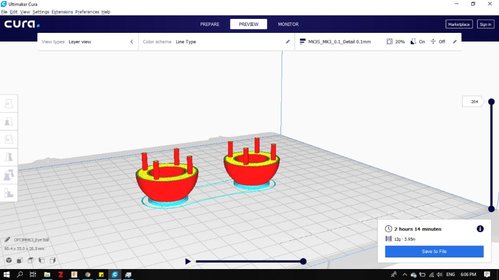
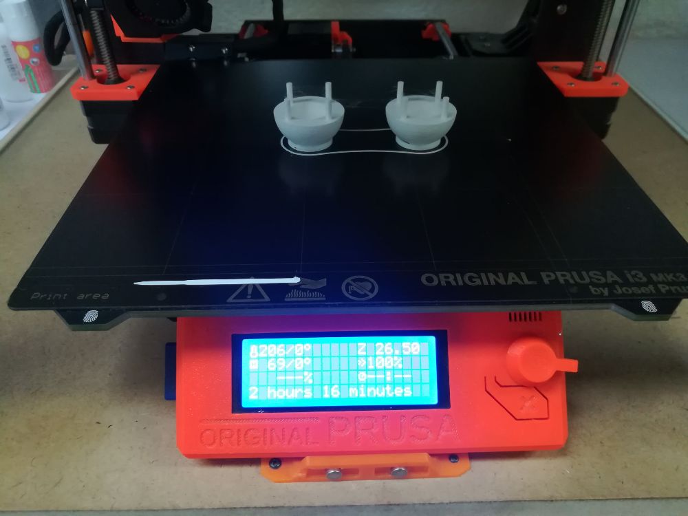
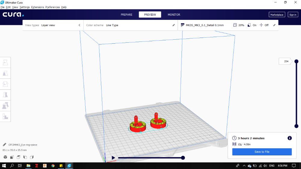
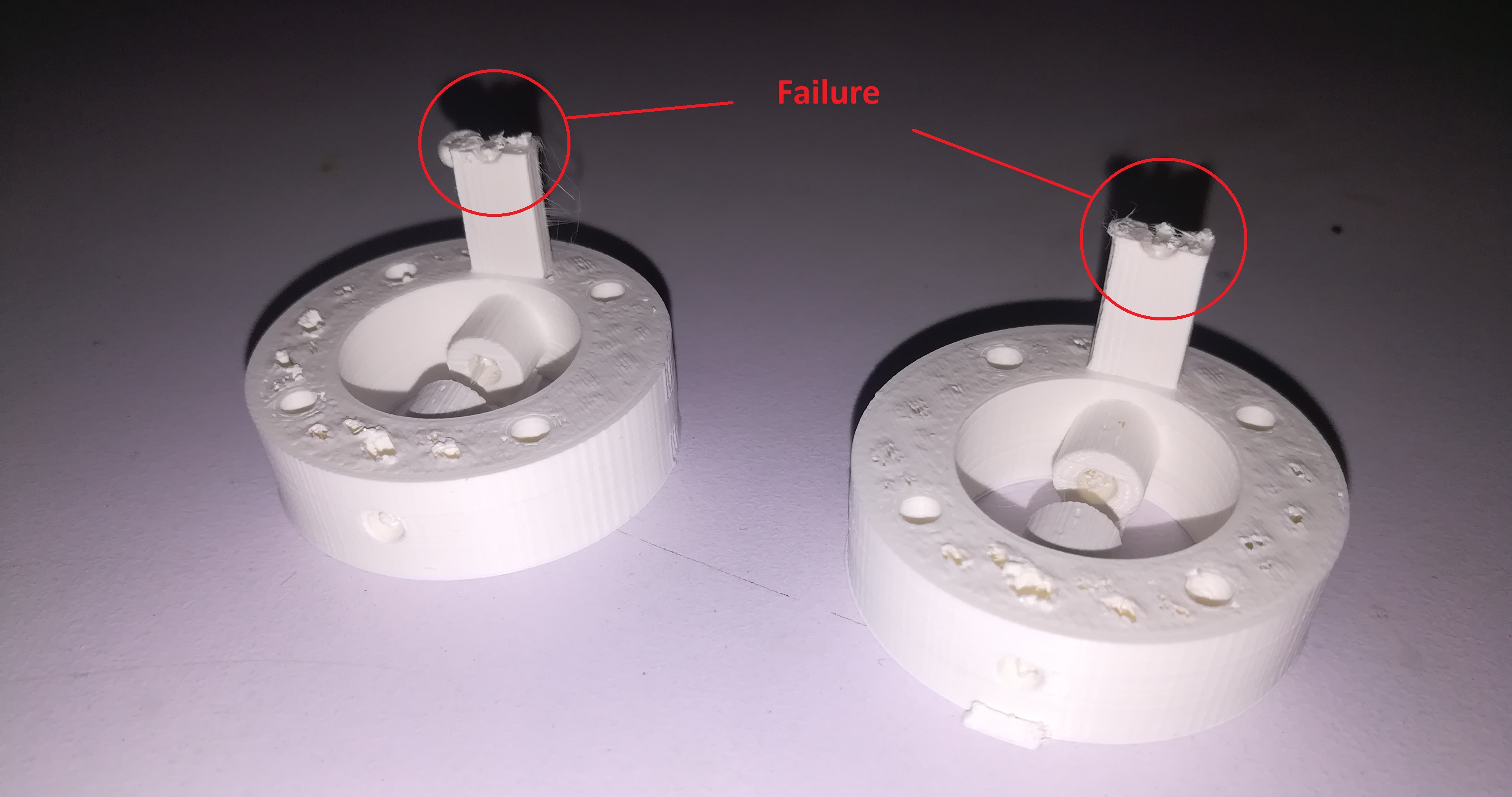
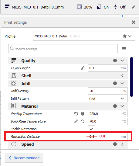
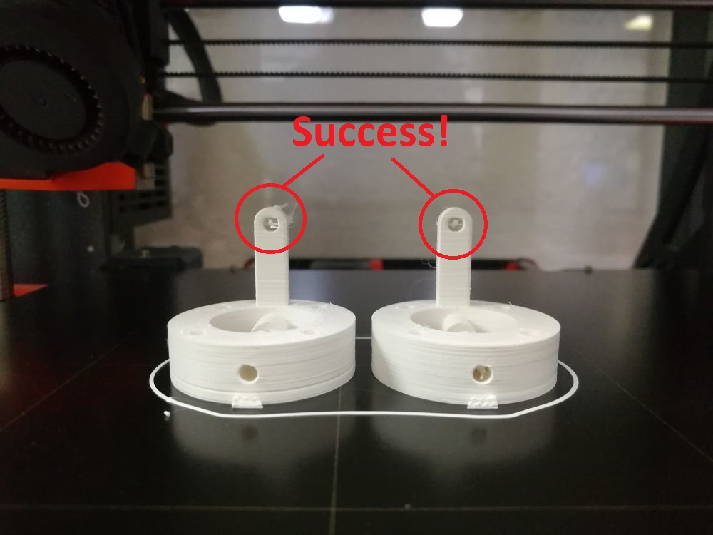
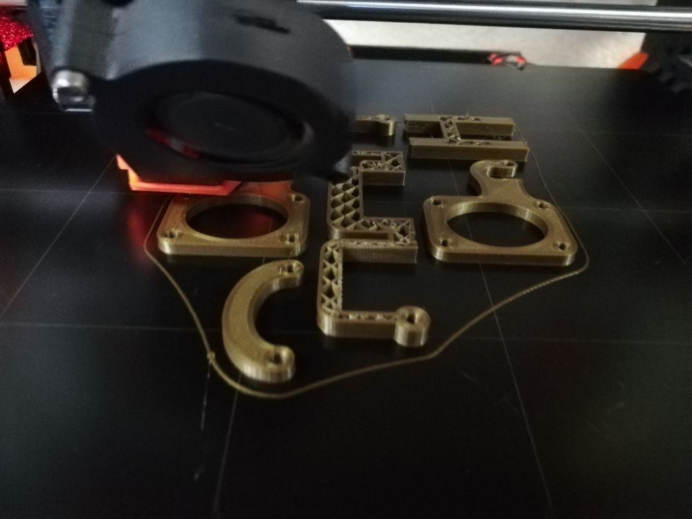
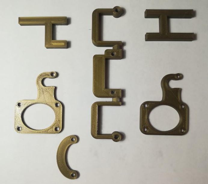
3D Printing
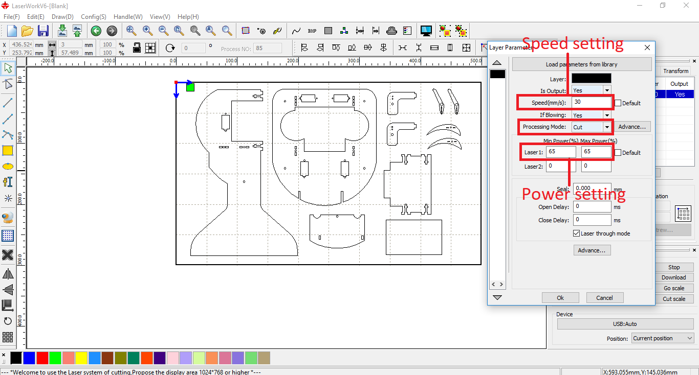
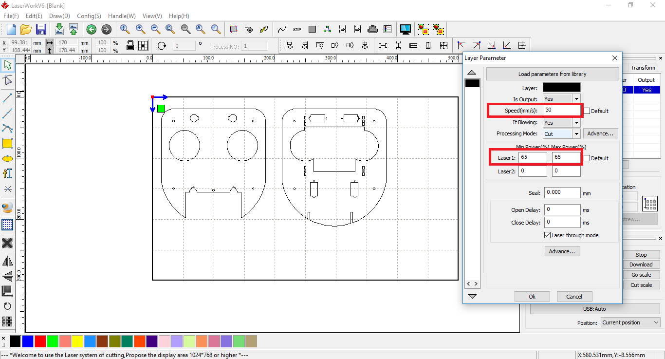
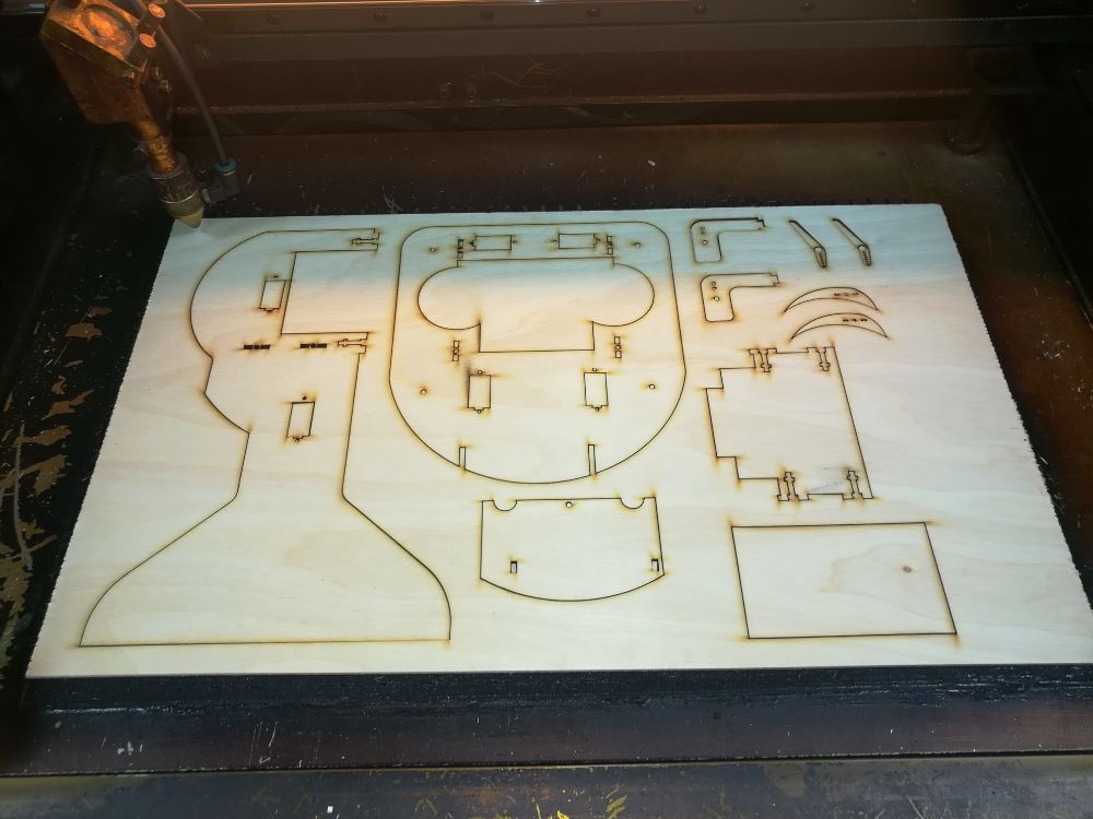
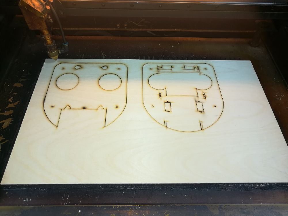
Laser Cutting
Electronics design & production
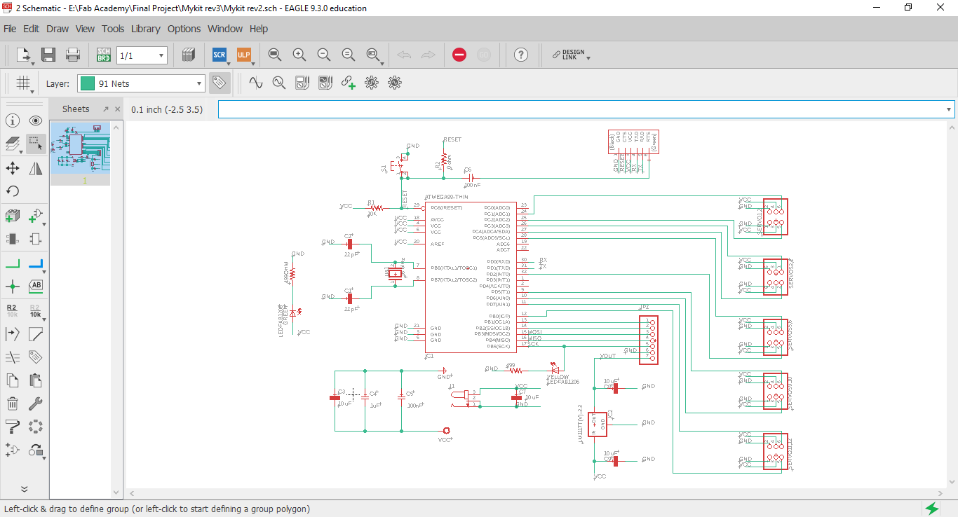
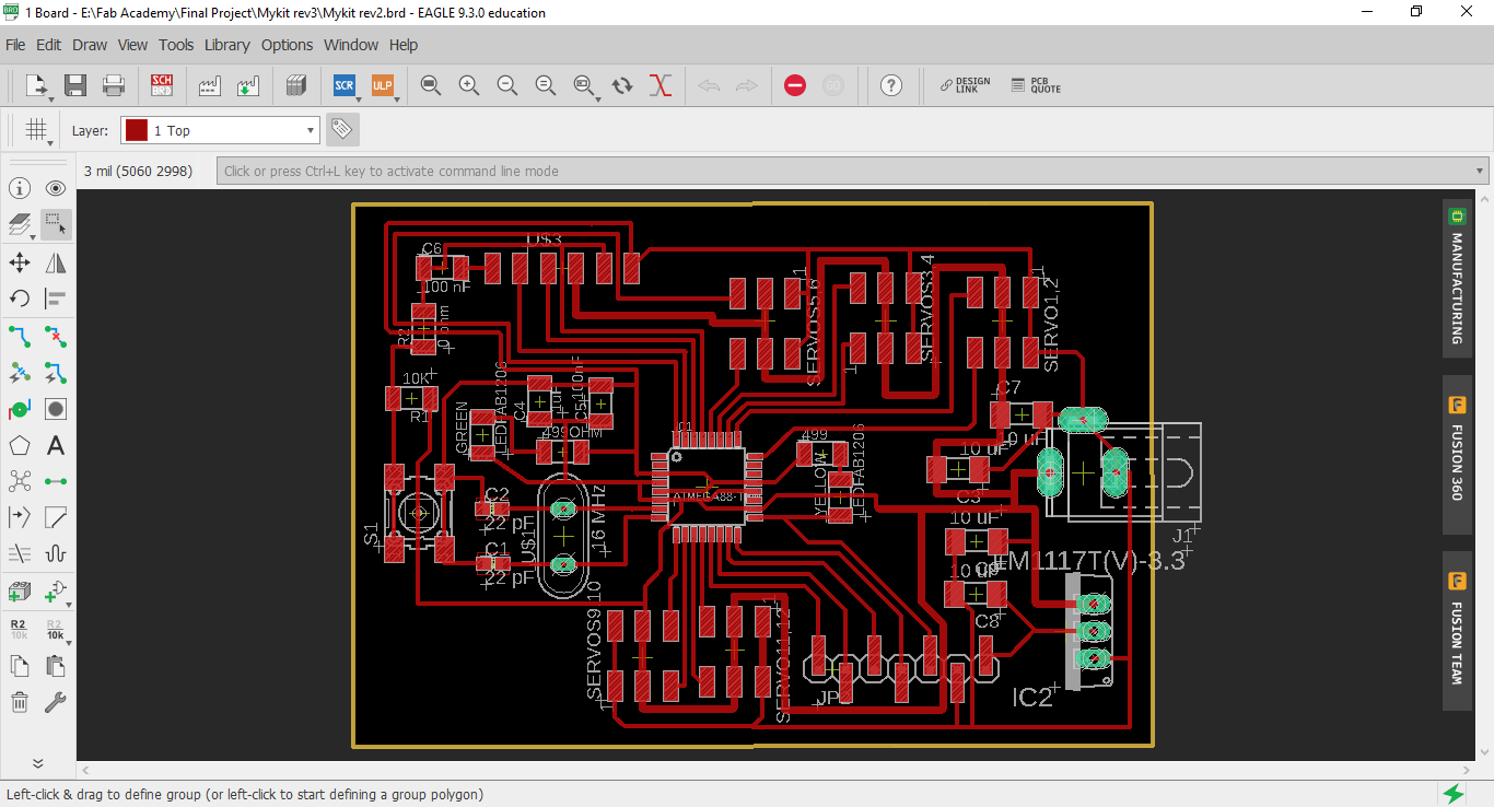
Electronics Design
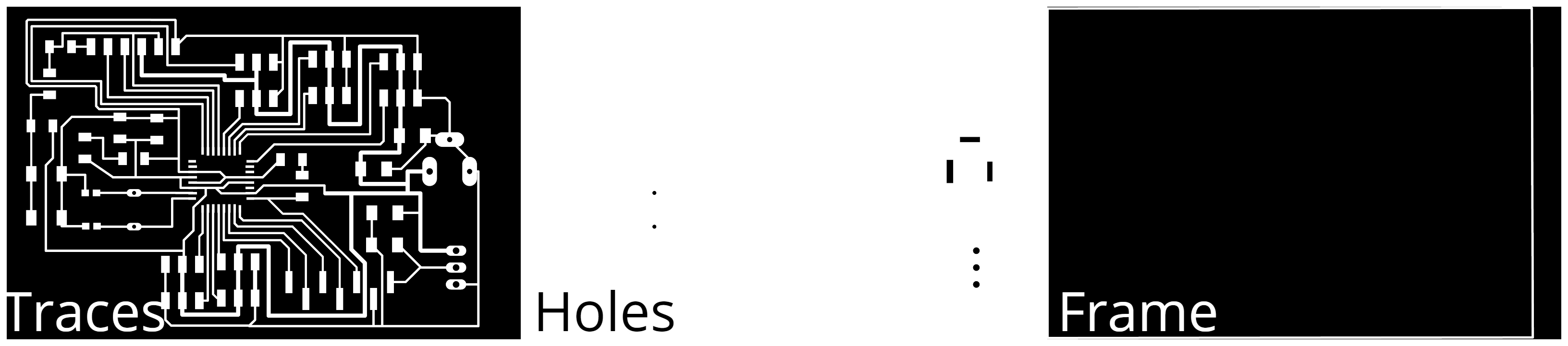
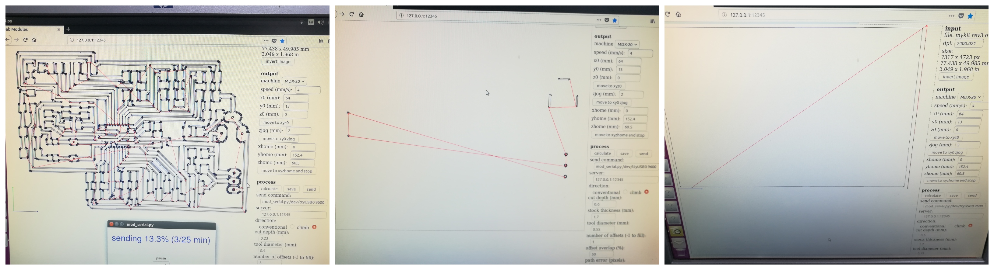
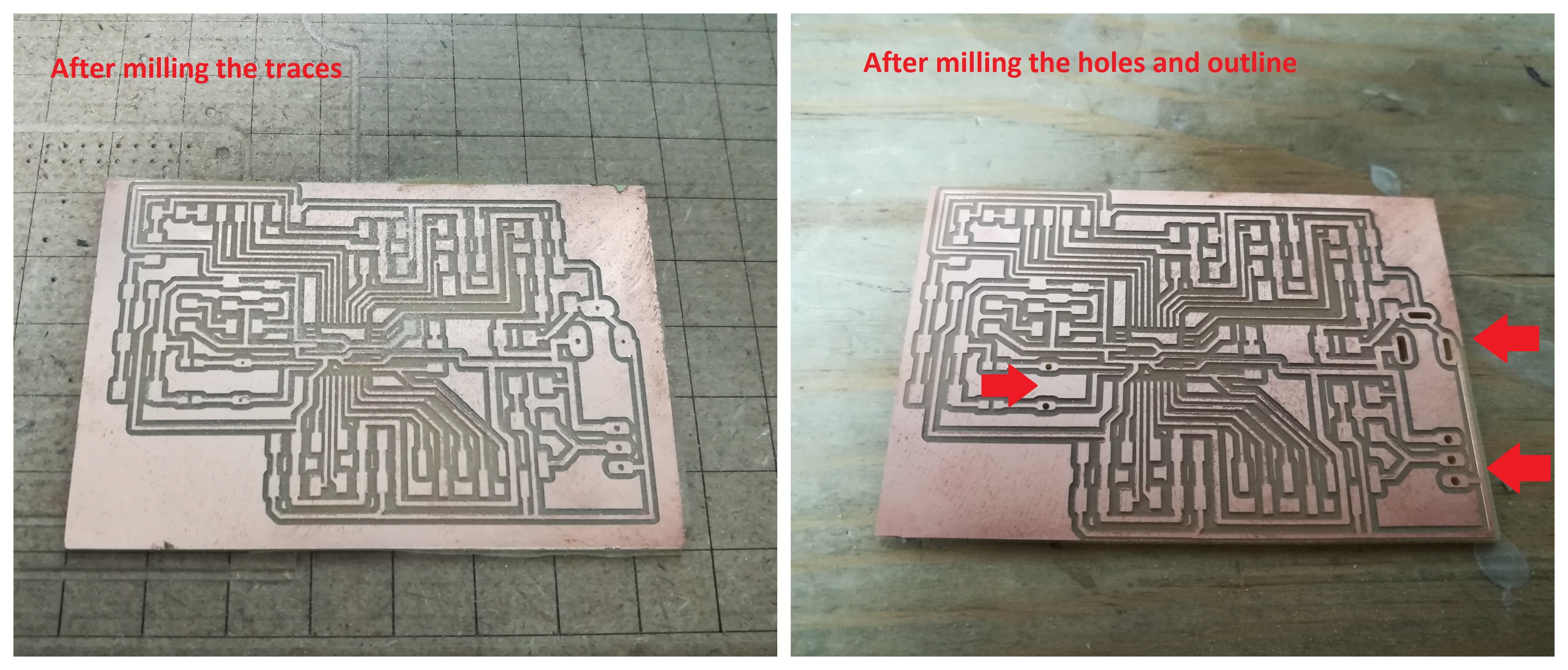
Electronics Production
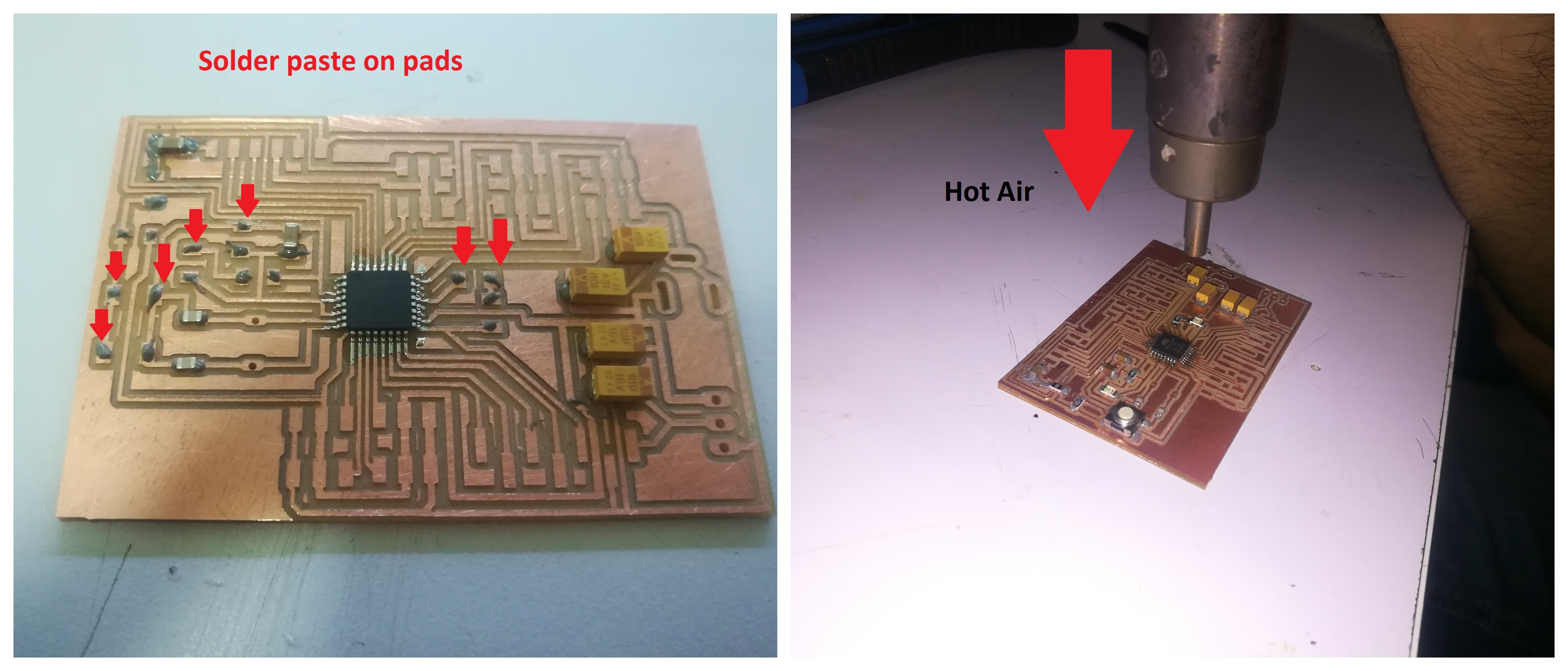
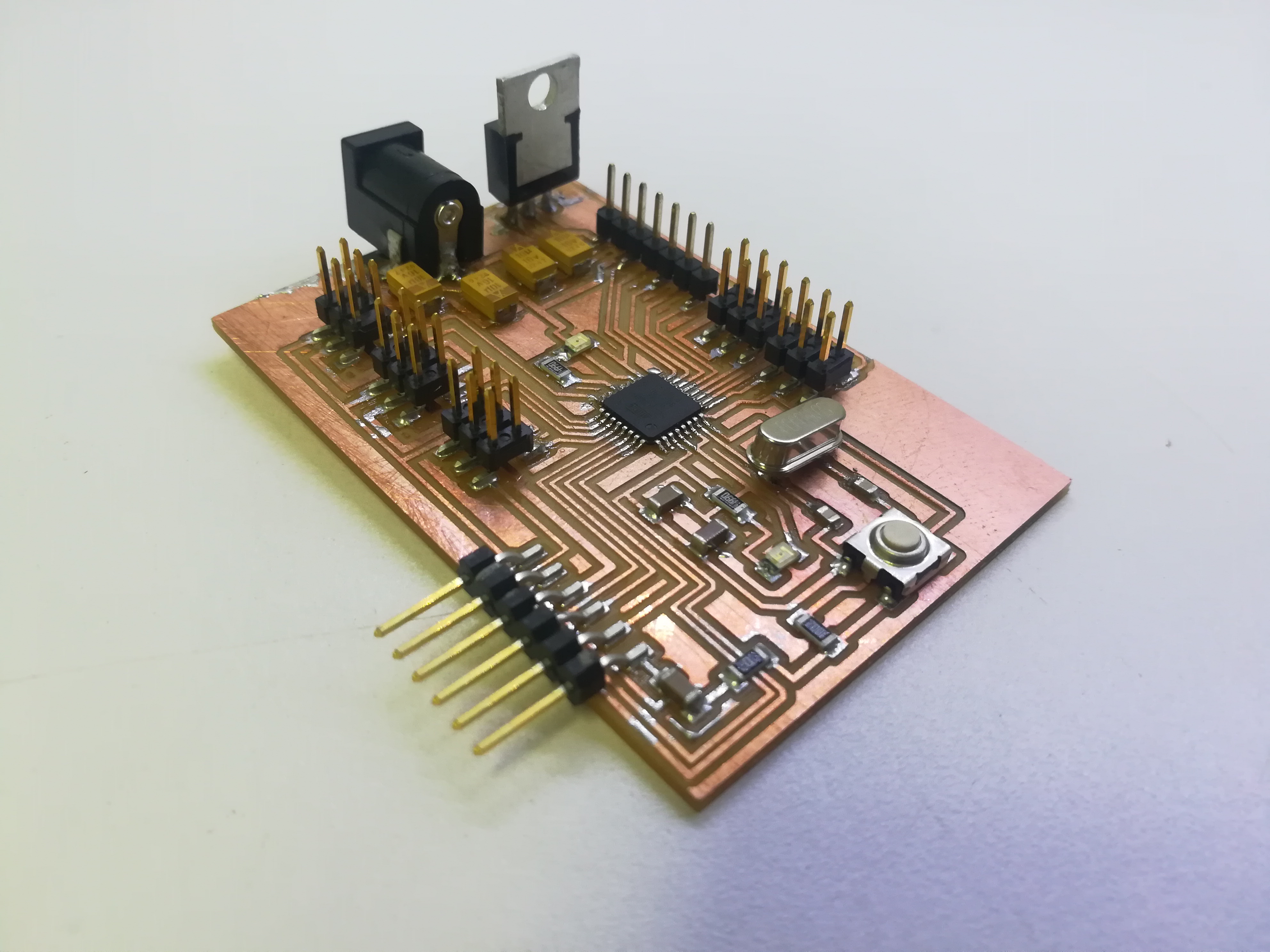
Integration
Embedded programming
Preparing RFID Cards
- The algorithm for Xpresso's facial expressions is as follows: an RFID card is present near the front panel, the robot will present a certain expression. This expression is unique to the card's ID.
- For this purpose, I need first to read the unique ID for the PVC RFID cards and dedicate each card to a single expression.
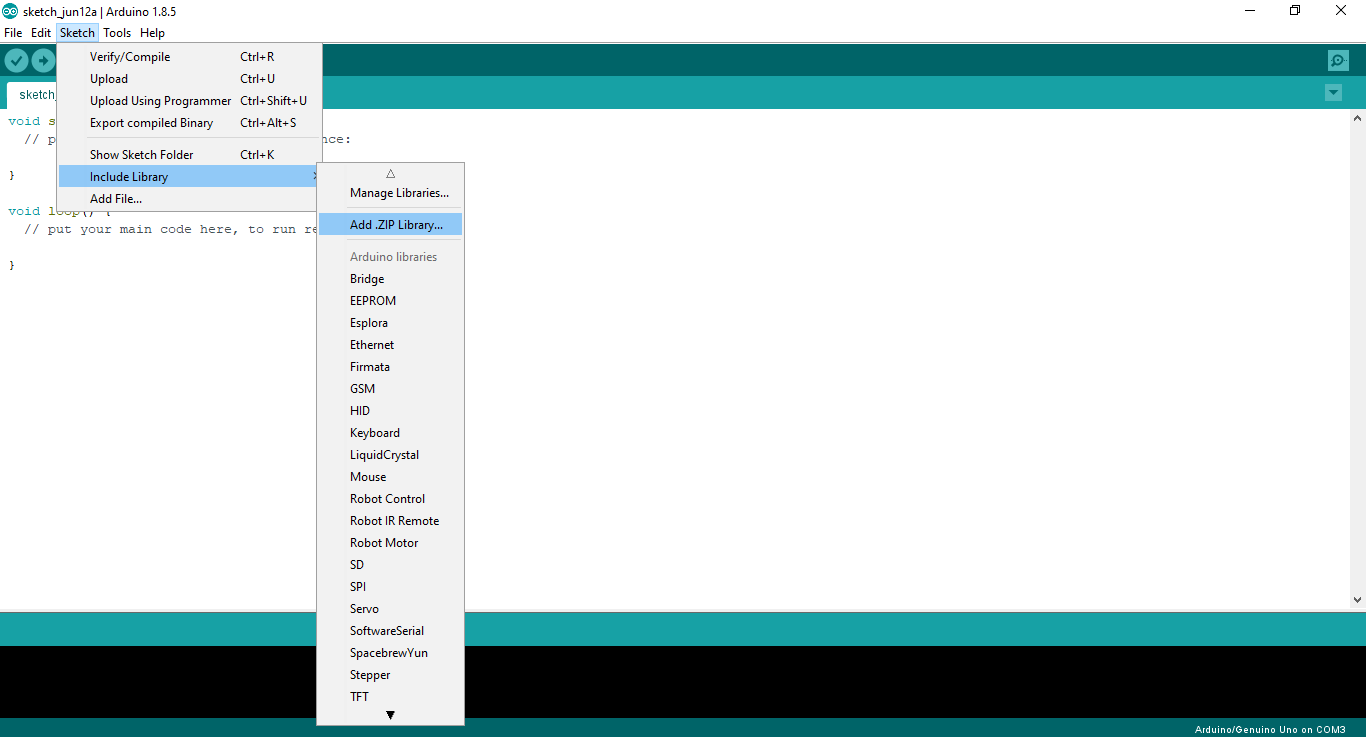
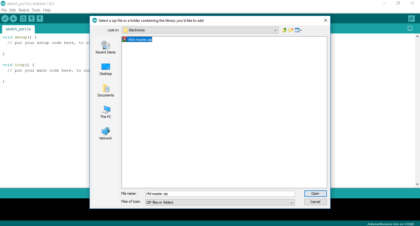
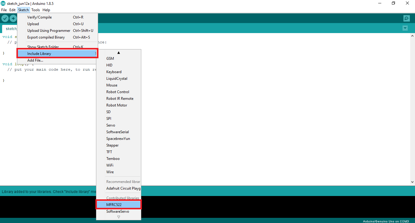
- But first to be able to work with MFRC522 RFID module, I downloaded and added the MFRC522 RFID library into Arduino IDE as shown below
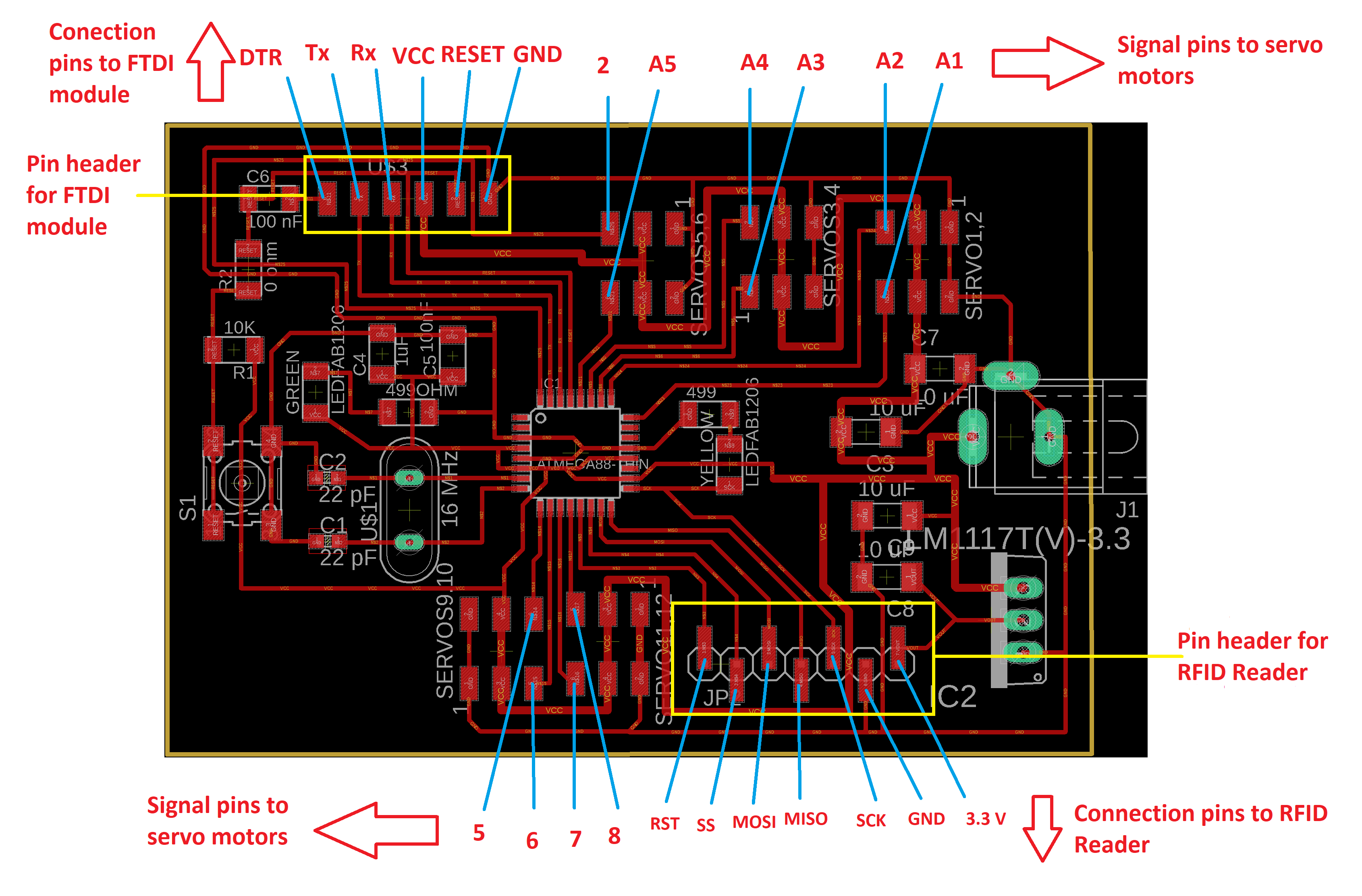
- I connected the RFID module to the RFID pins I dedicated for communication with RFID reader on Satchakit and connected an FTDI module to the FTDI pin header on Satchakit (see connections diagram below)
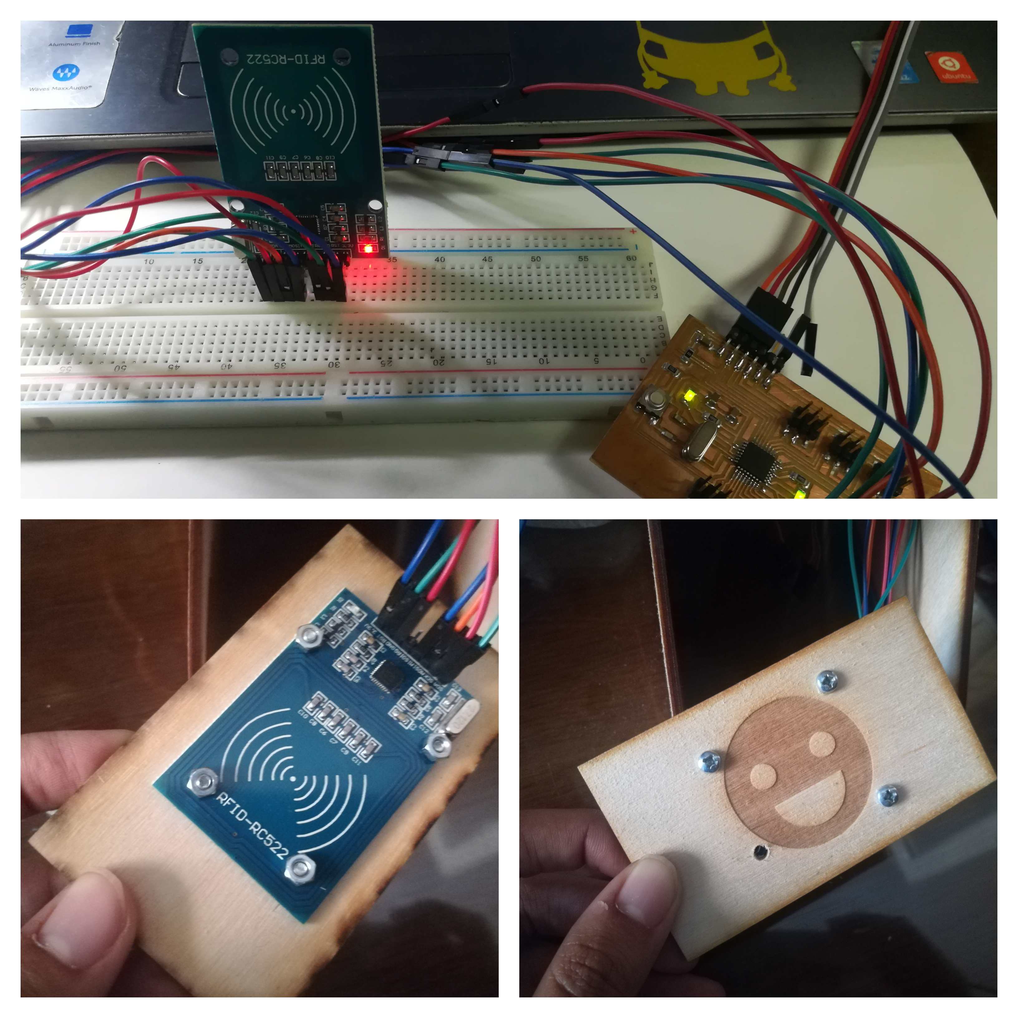
- For the testing of the RFID reader I used a breadboard first, then in the integration I fixed the RFID reader to the back of the front panel.
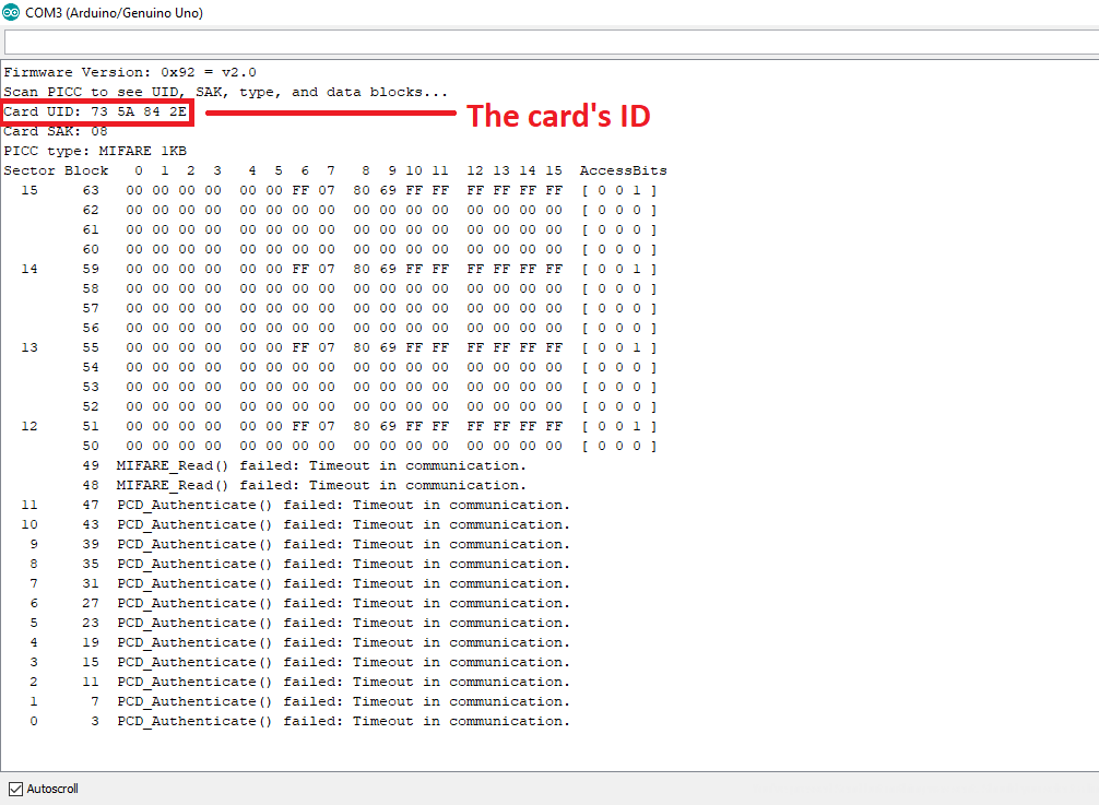
- I used the dumpInfo code, which reads the info on the card and output it on the serial monitor.
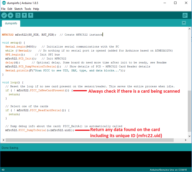
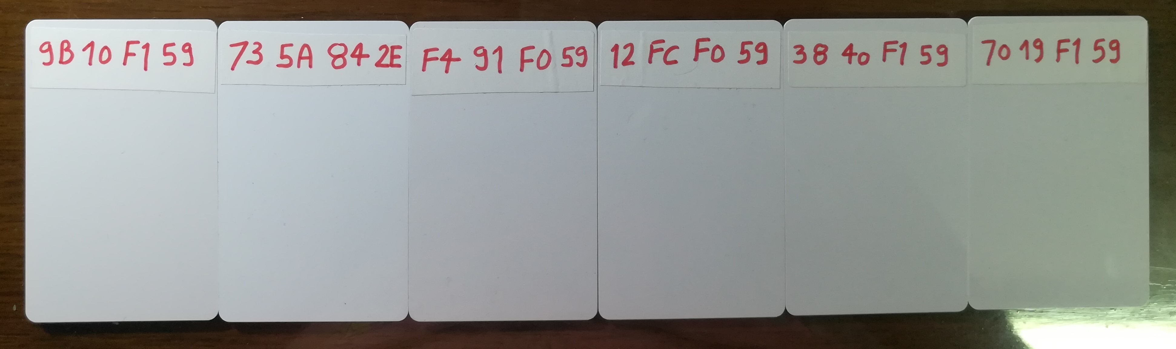
- I scanned every card, read and recorded the ID from the serial monitor as shown below.
- I dedicated a unique ID for every expression:
Expressions: Programming
- I needed to drive 5 servo motors, eyebrows (2), lips (2), and pan eyes mechanism (1).
- I attached these 5 servos to 5 PWM pins on Satchakit. While I designing the board I dedicated 10 possible PWM pins for driving servo motors, from which I chose 2,5,6, A5 and A4 to control the eyes, eyebrows and lips.
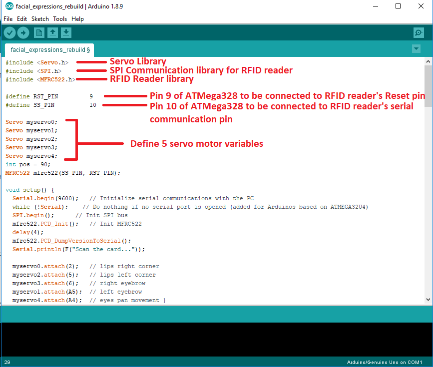
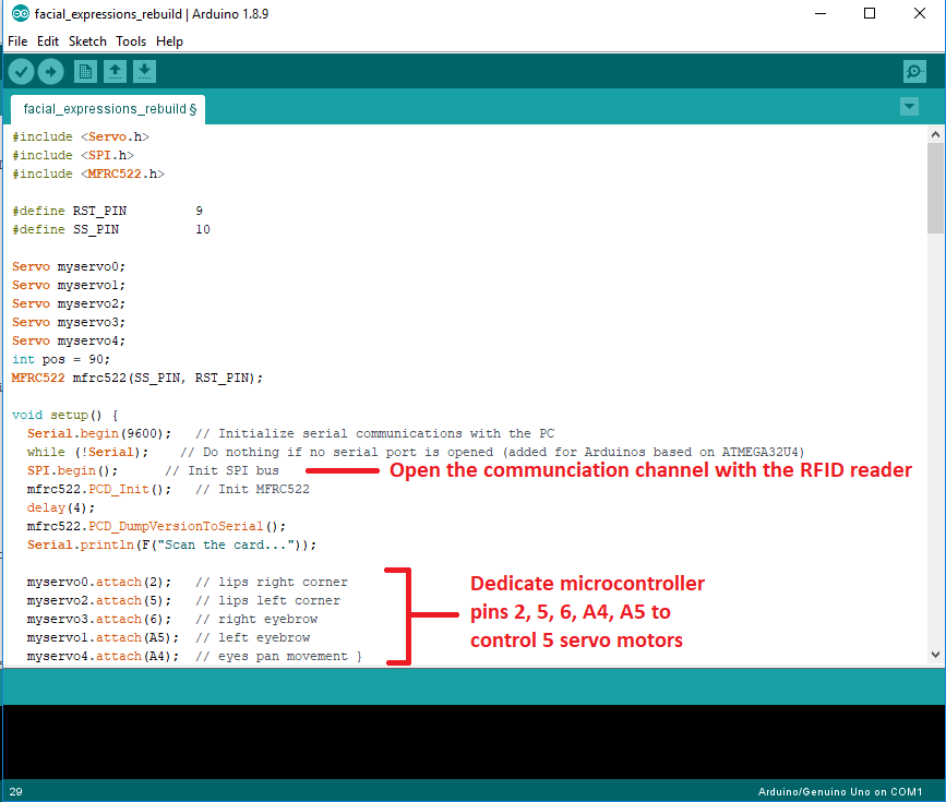
- The algorithm goes as follows: First I included 3 libraries, the servo motor library, the MFRC522 RFID library and finally the SPI communication library as this is the protocol that the RFID reader uses for communication.
- Next, I needed to dedicate 2 pins on the ATmega328P chip for Reset and serial communication with the RFID reader, which are pins 9 & 10.
- As I'm using 5 servo motors, I needed to define 5 myservo variables as well.
- In the Void Setup, I included a command for opening the SPI communication with the RFID reader, and the intiation command for the RFID reader itself.
- I also included the serial communication commands: Serial.begin(9600); Serial.println(F("Scan the card...")); which I used in the testing phase when I used the serial monitor to send confirmation messages for each expression, however these commands are not essential for the final demo considering that Xpresso doesn't have a screen to show these messages.
- Also the Void Setup is where I dedicate 5 specific signal pins for the servo motors that will animate the expressions, I chose pins 2, 5, 6, A4 and A5.
- In Void Loop, I included the main algorithm which is a series of if-else if-else conditions, the conditions are checked and if one is correct, the routine within is executed. The conditions are simply that RFID tags IDs have to be identical to one in the if condition.
- The routine for each facial expression rotates the servo motors with certain angles, animating the facial features to indicate a certain emotion.
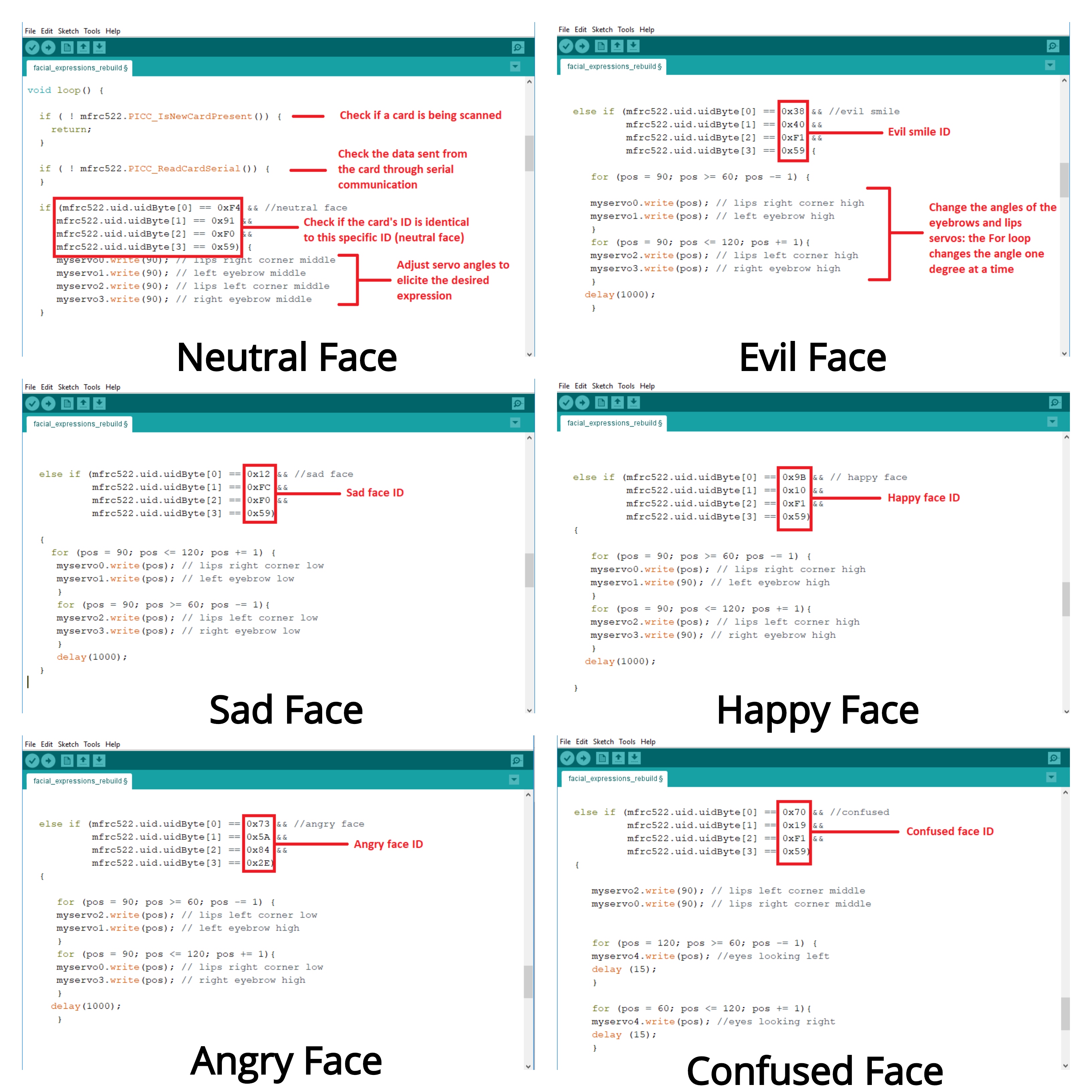
- Xpresso is programmed to express 6 different emotions:
Final Project Video
Acknowledgements
-
I would like to acknowledge:
- The work of daniele ingrassia, as I redesigned his Satshakit and integrated it into my projects
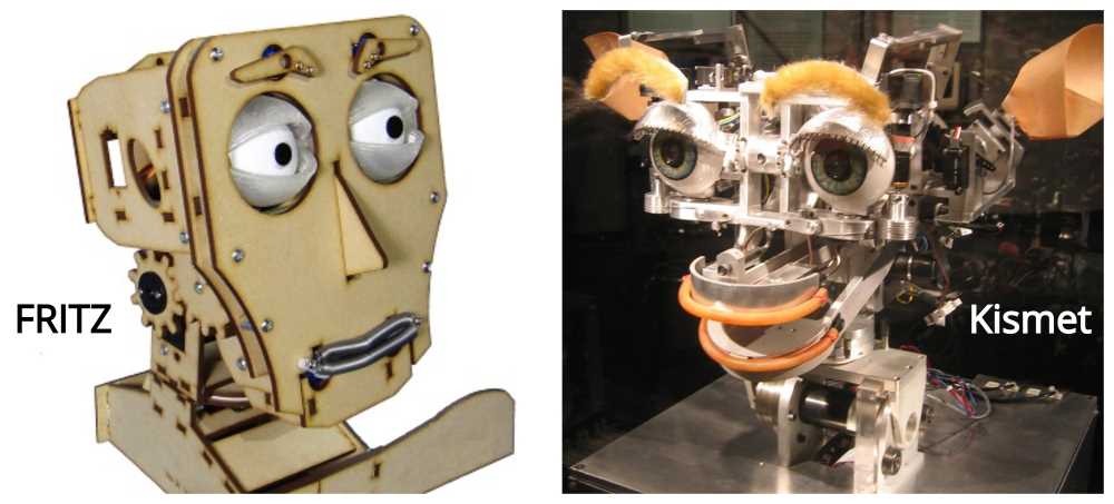
- The work of Instructables user hackintoshlover12, as I used the design concept and mechnisms of Fritz the robotic head as an inspiration source to redesign and create my own
- The work of Thingevese user nono78b, As I used the design concept and mechanism of Dasaki Compact Animatronic Eyes as an inpiration source to redesign and create my own
- My local instructors at FabLab Egypt, Mohamed Kamel & Mohammed AboelHaggag and FabLab Egypt's general manager Omar Elsafty for their continous support, giving us their valuable time, effort and knowledge.
- FabLab Egypt's technical team members Mahmoud Kotb, Mrehan El Shahawy and Mahmoud Aboelnaga for being supportive, and always open for questions and offering help.
- My regional Guru Ohadino Meyuhas for his constructive feedback on my work, for sharing his knowledge and for his continous support.
- My global evaluator, Santi Fuentemilla, for his constructive comments and feedback.
- American Center Cairo (ACC) at the U.S. Embassy in Egypt for partially funding my Fab Academy diploma.
- Last but not least, my Fab Academy 2019 classmate Nada Abdelfattah for always sharing her knowledge and expreience without limits. I'm a big believer in peer learning, and from Nada I learned TONs! Thank you my friend :)
License
Creative Commons Attribution-NonCommercial-ShareAlike 4.0 International (CC BY-NC-SA 4.0)
Design Files
- Final project video
- Final project slide
- 2D Design Files
- 3D Design Files
- Fusion Design File
- Electronics Design & Production Files
- Code files