Computer-Aided Design Week #3
Introduction
This week I’m going to work on visualizing my final project using 2D and 3D design tools. I chose 2 design software as follows:
- 2D CAD tool #1: Inkscape
- 2D CAD tool #2: Autodesk Fusion 360
- 3D CAD tool: Autodesk Fusion 360
Design Concept
Coming up with a design concept for the animatronic head proved to be challenging. I had two options for the concept:
- Option 1: To design an animatronic head that resembles humans.
- Option 2: To design a cartoonish and whimsical animatronic head with exaggerated features
- Eyes
- Eye brows
- Lips

2D CAD tool #1: Inkscape
- I used Inkscape to visualize 4 emotional states: Neutral, surprised, angry and upset. I will first demonstrate how I used Inkscape to design the neutral state, then I will demonstrate the other 3 variations.
- I downloaded Inkscape for Windows from the link: https://inkscape.org/release/0.92.4/windows/
- To get started with Inkscape, I went through some video tutorials that were shared by our local instructor. These tutorials were originally prepared for the Mini Maker Diploma organized by Fab Lab Egypt
- I wanted to design the robot’s eye to resemble Wall-E’s, the robot from the famous animation movie!
- I started with drawing a rectangle with the dimensions: 70 mm * 50 mm
- To change the rectangle from filled to border lined, I clicked on Objects in the tool bar, then Fill and Stroke. I finally changed the width of the border to 2 mm
- I will use this rectangle’s corners as placing points for the arc that will shape the eye.
- From the tool bar on the left, I clicked Draw Bezier curves icon. I placed the tool tip on the upper right corner and clicked to place the first node, then moved to do the same with the lower right, lower left, upper left, and back to the upper right corners, respectively.
- Now that I have the water drop shape, and I can delete the rectangle as I no longer need it.
- I will then proceed to draw the eye ball and iris, by clicking on the circle shape from the tool bar on the left.
- I now need to align the iris exactly in the center of the eye ball. To achieve this: click Objects>>>Align and Distribute, then select the circles that I need to align. From the box that appeared on the left click Center on vertical axis, then on Center on horizontal axis, as shown below.
- Now that the iris is aligned in the center of the eye ball, I can place them inside the eye. Then to create the left eye, I will copy the complete right eye from Edit>>>Clone>>>Create Clone. Finally, I will flip the clone horizontally to be like a mirror image. Now the first feature, the eyes, are done!
- I will move on to draw the eye brows, but first I need some guidance on where to place the brow, so I made use of the page grid view in Inkscape for this purpose.
- Then, I will simply use the Draw Bezier curves tool to draw the left brow using three nodes, then I will clone, flip and place it as I did with the eye.
- Finally, I created the upper lip using Draw Bezier curves tool as I did with the brows, by placing 5 equally spaced nodes, to form a straight line
- Then, I cloned the upper lip to create the lower lip
- This is considered the robot’s neutral face expression.
- Now, to convey the upset, surprised and angry expressions, I cloned the neutral expression and started with adding a very important feature, which is the eye lids.
- Starting with the upset expression, I drew a line over the iris, and filled the area above it using the Fill bounded area tool in the left tool bar.
- To convey the upset expression, I needed to lower the eye brows and manipulate the lips.
- Now, the five nodes that I placed when I created the lips, makes it very easy to manipulate the line.
- I used the Edit Paths by Nodes too from the tool bar on the left. I now can easily drag the nodes in any direction to convey the expression.
- By repeating the same techniques from above, I was able to manipulate the face features to convey the surprised and angry expressions.
2D CAD tool #2: Autodesk Fusion 360
- The second software that I used to design parts of my final project is Autodesk Fusion 360. In this section I'm describing how I used the software to perform 2D design.
- The part that I chose to design in 2D is the "Face" of my robot.
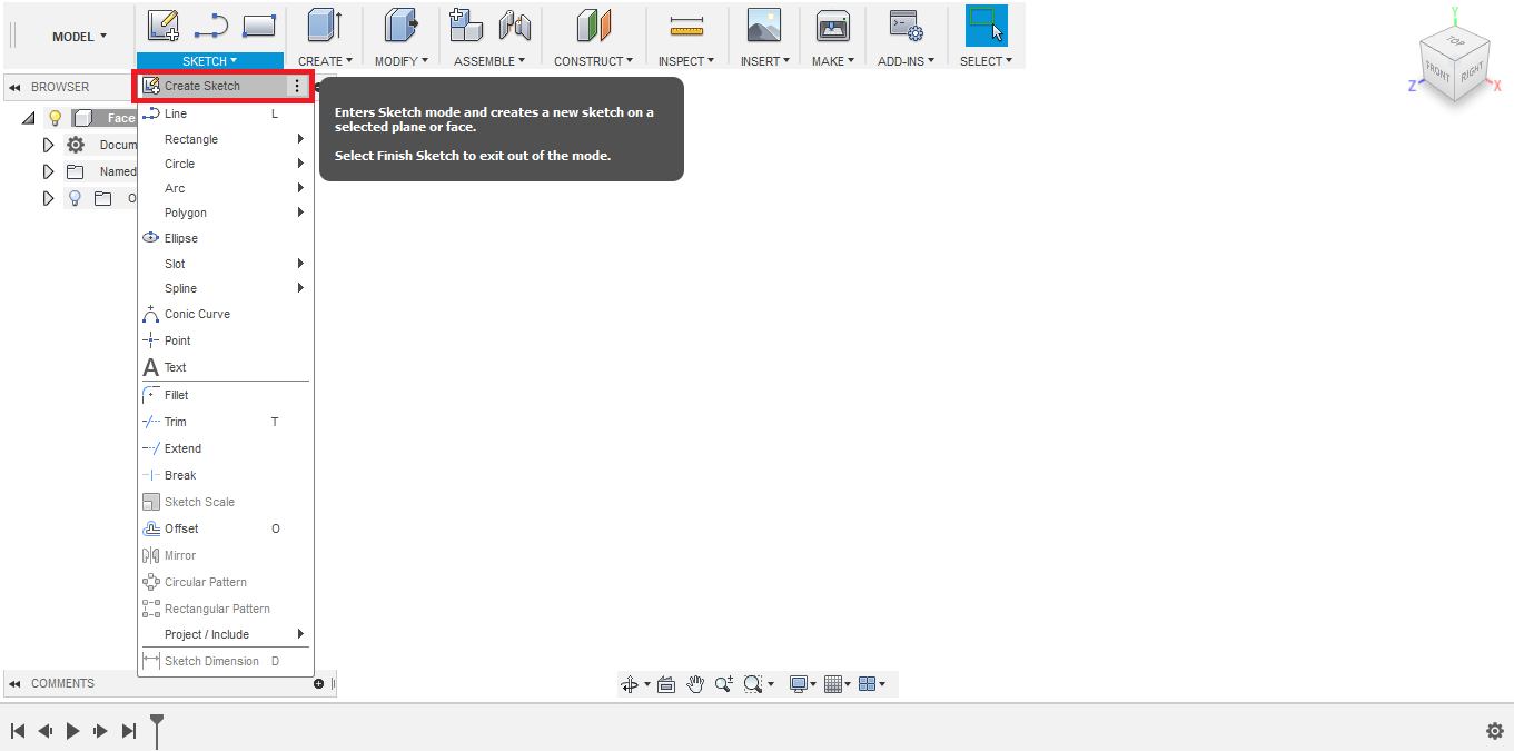
- I started with creating a new Sketch.
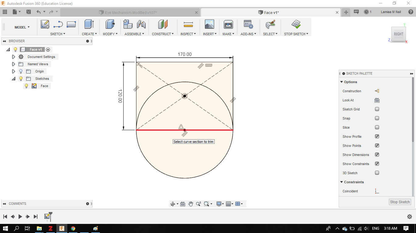
- To sketch the upper half of the face, forehead and eyes area, I created a rectangle: with 170 mm length and 120 mm width


- To sketch the lower half where the mouth and chin are located, I created a circle, with 85 mm radius.


- Now, I needed to remove the upper half of the circle, leaving only the lower half, I used the Trim tool.

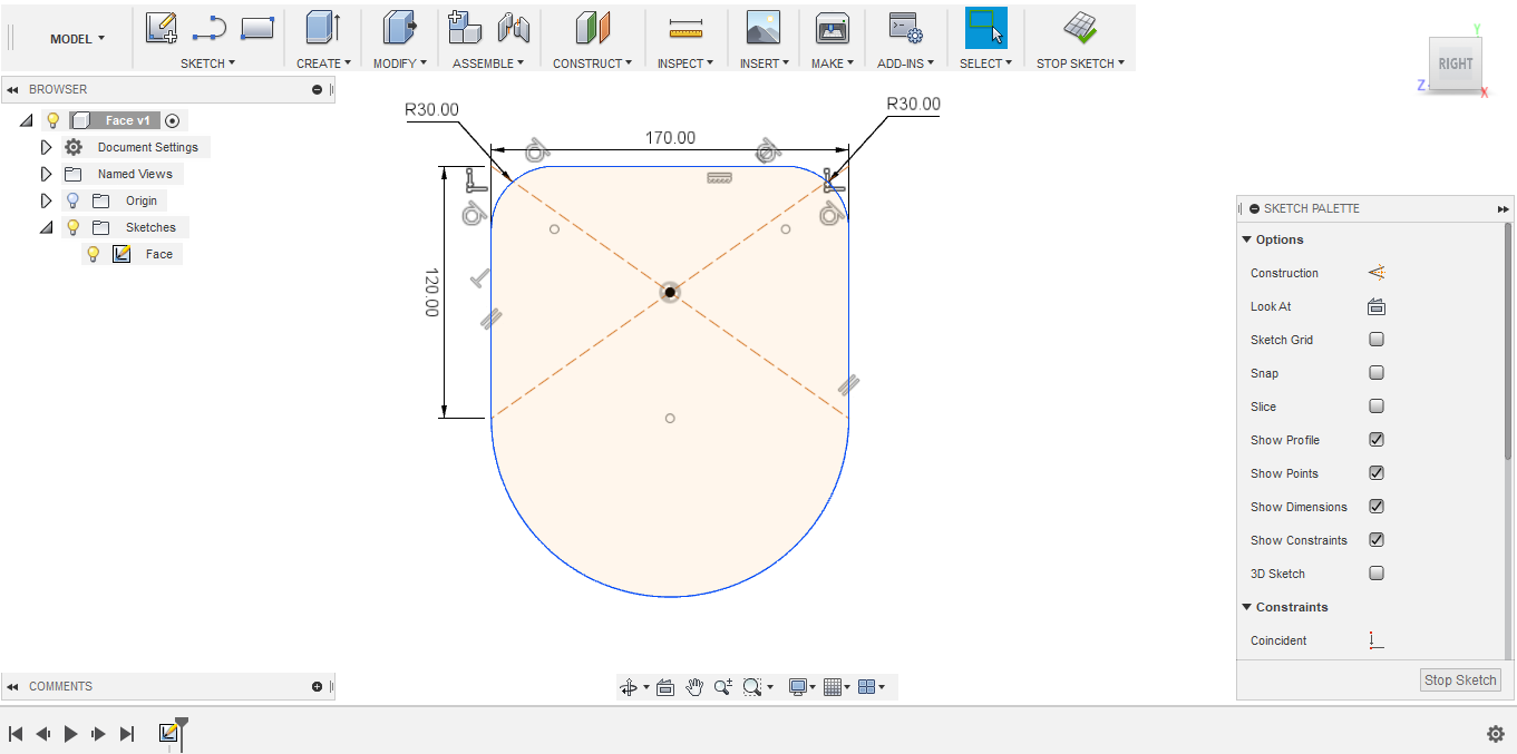
- To smooth sharp corners, I used the fillet tool, which is a curvature of a certain radius between two lines. In this case, I set the fillet radius to 20 mm.


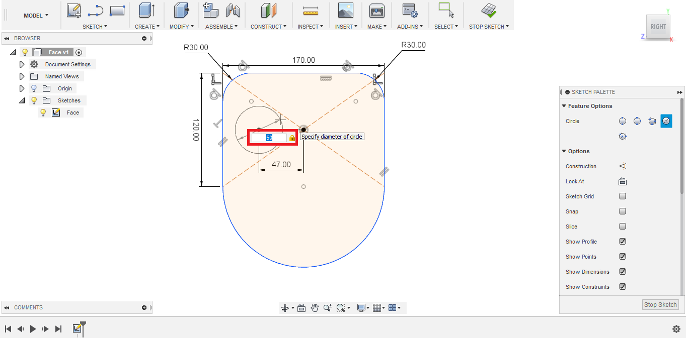
- Now, I moved on to sketch the eyes openings. I drew a "construction line", which is basically a guiding line for me to place the center point of the eye opening circle. I placed the first point of the line at the center point of the rectangle that I created earlier and second point at 47 mm distance from first point, considering I want the eyes to be 94 mm apart (from center to center).

- I created another circle with 50 mm diameter for the right eye opening
- To sketch the left eye, I decided to use the Mirror tool. But first I needed to create a mirror line. I created another construction line the divide the face into two equal halves.
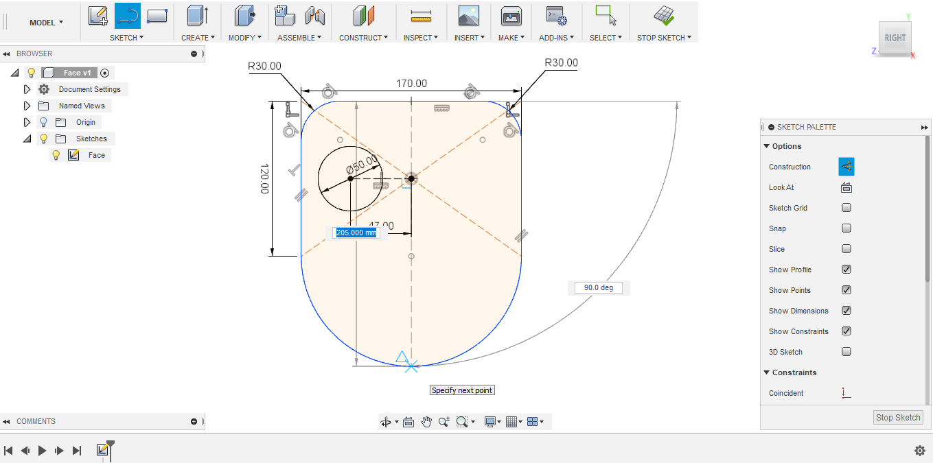
- Now I choose the Mirror tool

- Then, choose the object that I want to mirror, and the mirror line that I drew earlier.
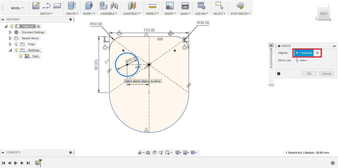

- And now I have a rough sketch of the face for robotic head

- Later on in my final project development phase I upgraded that sketch, actualy created two different layers of the Face, one lower layer for press-fitting and servo motors fixtures. And an upper layer (facade-like) to cover up the lower layer.

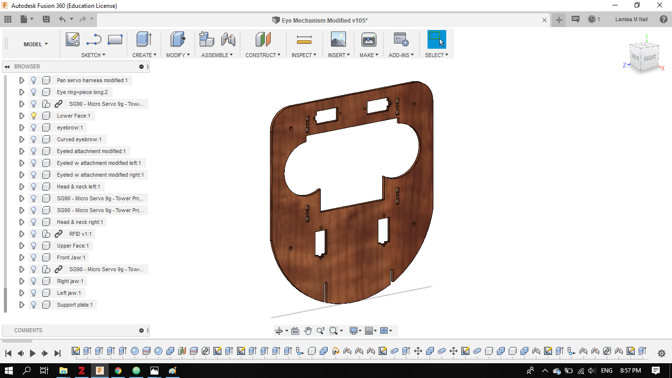
- Finally, I exported these 2D sketches in an DXF format for Laser cutting

3D CAD tool #3: Autodesk Fusion 360
- For the 3D part of this assignment, I decided to create a rough design for the Eyeballs of the robot, using Fusion 360 as well.
- For this purpose, I created a sphere with diameter 35 mm


- I'm planning to fabricate the eyes using 3D printing, so to save printing material, I decided to hollow the eye structure from the inside. To do so, I created another smaller sphere, with 20 mm diameter, with its center located at the center of the bigger sphere.

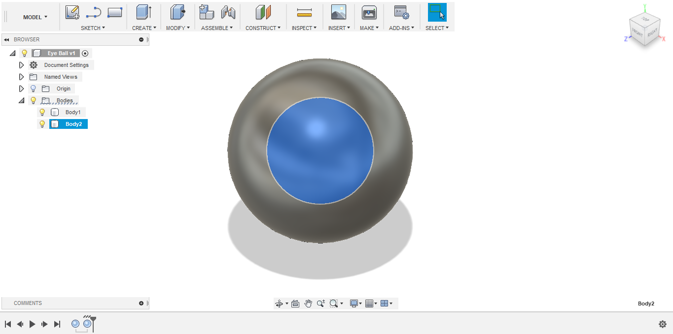
- To evacute the bigger sphere, I used the combine tool, selected the two spheres, and changes the operation to Cut.


- I don't need the entire sphere to simulate the eyeball, only one half is needed. So I used the Split tool.
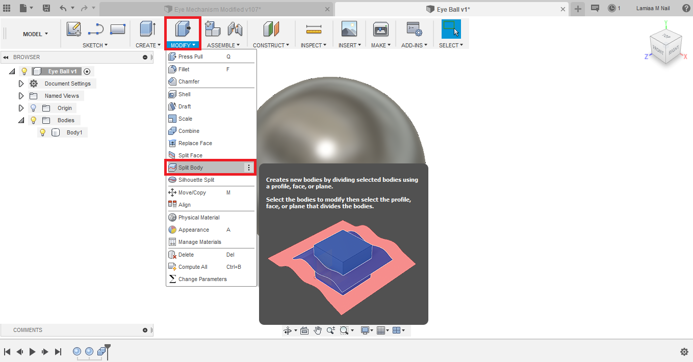


- Now I have the rough 3D design on the eyeball.
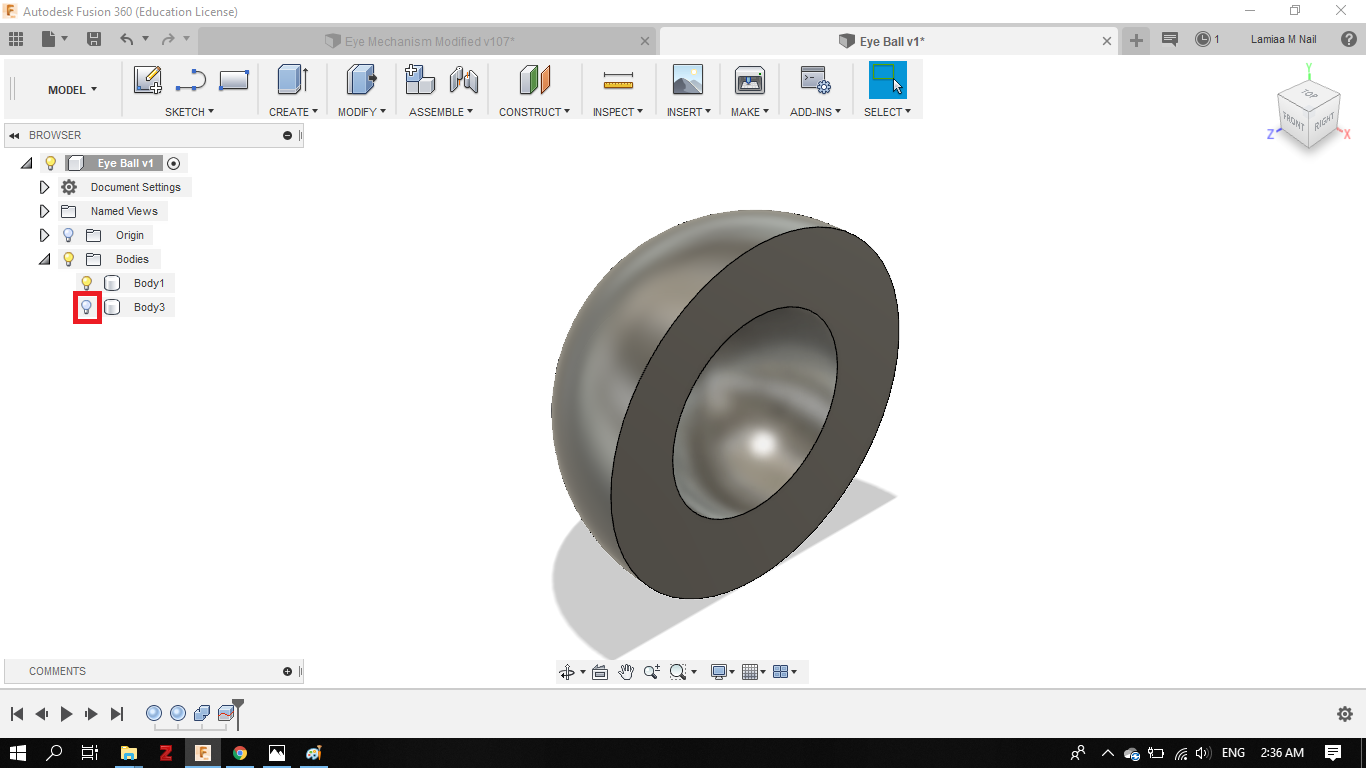
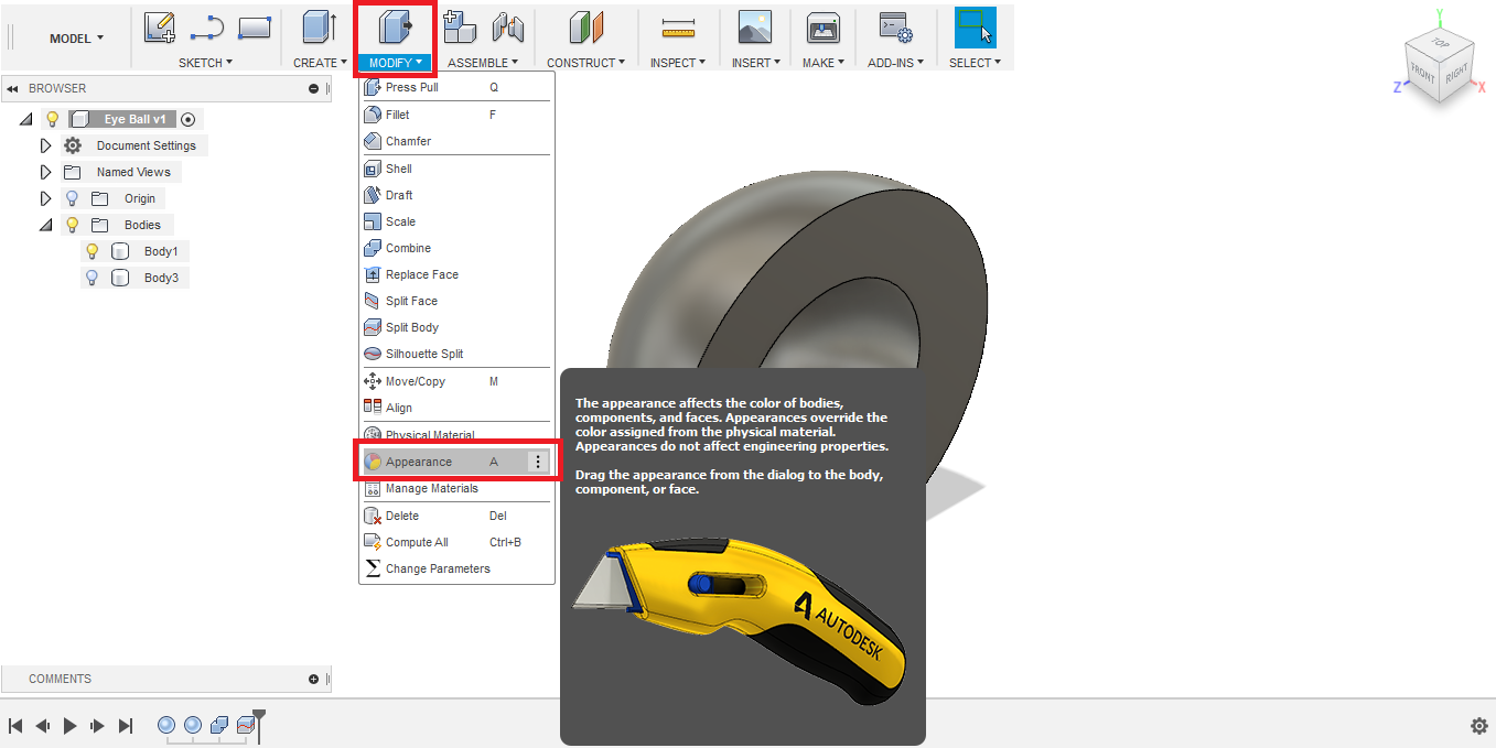
- To give it the physical appearace of the an eye, I used the Appearance tool.
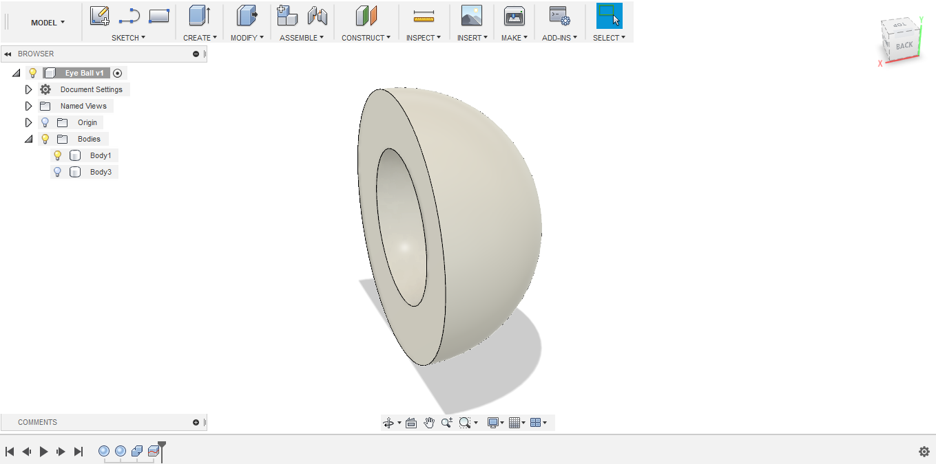
- I browsed the materials library, from Plastics, I dragged the ABS white and dropped on the 3D object.

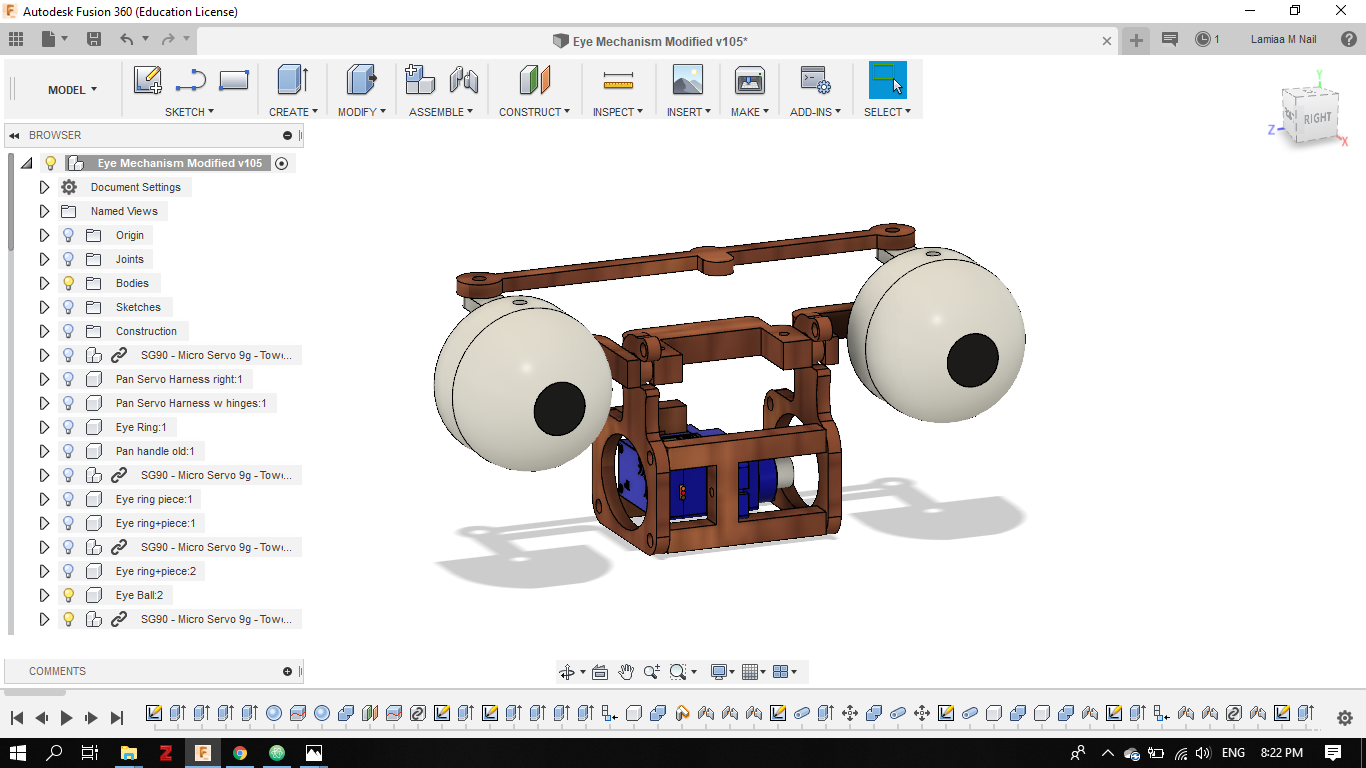
- Later on in my final project development phase I completed the entire Eye tilt and pan mechanism, using a combination of 2D and 3D design using Fusion 360.
Conclusion
- Using Inkscape for the first time is not easy, although it seems very trivial! I liked the fact that I can do 2D design easily, however if I want to change or edit later on my design, it is like starting all over again! considering that the software isn't parametric.
- This isn't my first time using Fusion 360, however the software keeps amazing me, and I still have a lot to learn. The software enables me to do parametric 2D design, in constrast to Inkscape. The 3D design experience in Fusion is intriguing, the ability to animate, render and simulate brings the designed parts to life! That's why I chose to use it in designing my final project.
Design Files