Computer-Controlled Cutting Week #4
Introduction
This week we have three main assignments:
- Characterize your lasercutter, making lasercutter test part(s), making test part(s) that vary cutting settings and dimensions. (Group assignment)
- Cut something on the vinylcutter (Individual assignment)
- Design, lasercut, and document a parametric press-fit construction kit, which can be assembled in multiple ways. Account for the lasercutter kerf. (Individual assignment)
1. Lasercutter Characterization (Group Assignment)
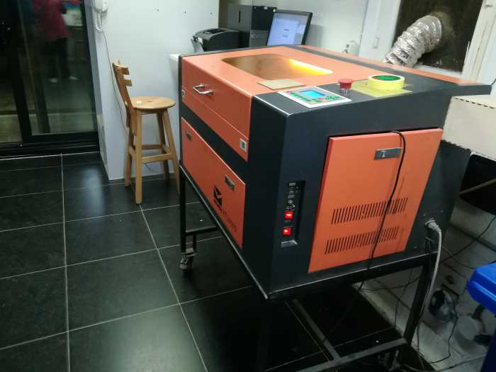
1.1 Varying Cutting Settings
- The first test I did with my teammates, is varing one of the lasercutter parameters while holding the other parameter constant. The two parameters under test here are the cutting/engraving power and the cutting/engraving speed.
- The template designed by Haitham Abdelkhalek , a former Fab Academy student in 2018, was used to obtain the optimal settings of the lasercutter.
The template consists of small 20x20 mm squares. Each square is set to a certain cutting/engraving speed and power. The first row of squares is set for engraving with a constant speed of 200 mm/s, and the power starts with 10% and increases by 10 for every next square, reaching 80% by the last one.
with a constant power of 75%, and the speed starts with 15 mm/s and increases by 1 mm/s for every next square, reaching 23 by the last one.
- Using Laserworks V6, we were able to set the power and speed for the squares, each of which is indicated with a different color for visualization. We set the mode to cut for cutting, and scan for engraving.
- We finally downloaded the file on the lasercutter. And the result as shown in the photo below, for the engraving, the squares got darker as the power increased, which can be useful for showing color gredient in a specific project.
For the cutting, as shown, the first two squares only were cut, while the others didn't. This makes sense considering that as the speed increase, the laser beam don't stay at one point long enough to penetrate the 3 mm thickness of the wood. Our conclusion from this test that setting 75% power and 15 or 16 mm/s speed will be optimal for cutting.

- We finally did the comb test to discover the laser kerf. We again used the template designed by Haitham Abdelkhalek The comb was designed with constant width notches, while the spacing between them increases with 0.1 mm increaments, starting with 2.8 mm and ending at 3.5 mm.
- We imported the design into the LaserWorks V6, and set the power to 75% and speed to 15 mm/s.
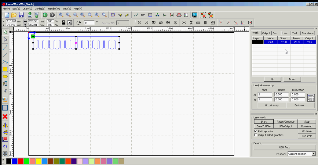
- However, we faced a problem. The combs didn't even come out of the wooden sheet after cutting. So, we had to decrease the speed of cutting below 15 mm/s until we the comb was cut at 12 mm/s speed.
Our hypothesis is that the quality of the plywood sheet is very low to the extent that it's composition is inconsistent along the sheet and even varies from one sheet to another.
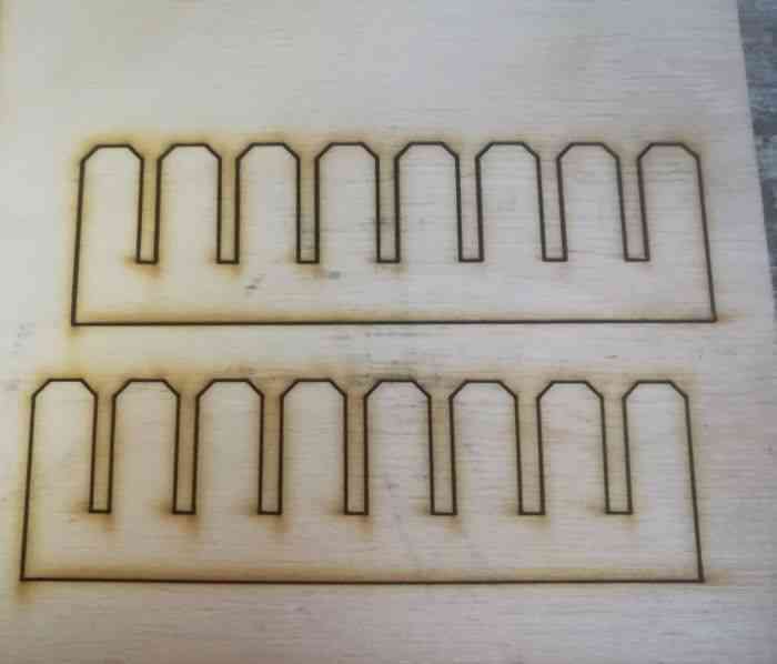
- Finally we cut the combs, and started fitting them together. We found that they press-fit very well at the second slot where the width was originally designed to be 2.9 mm.
We used the caliber to measure the actual width of the slot after the kerf affect, and we found it around 3 mm. We concluded that the difference between the actual and designed width account for the kerf which is 0.1 mm.
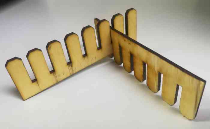
- Conclusion: optimal speed: 12 mm/s, optimal power: 75% and kerf: 0.1 mm.
2. Cut Something on the Vinylcutter (Individual assignment)
2.1 How did I drew my file?
- For this assignment I chose to draw a Minion, the famous character from the animation movie "Despicable Me".
- I used Inkscape to design the file, and to draw the character I followed this video tutorial: https://www.youtube.com/watch?v=f5maAp8pdsc
- I started with drawing a rectangle using the rectangle tool in the left vertical bar
- Then, I used the edit paths by nodes tool to reshape the rectangle into an eliptical shape.
- Next, I used the circle tool to draw the goggles and eyes.
- Final design:
2.1 Vinyl Cutting
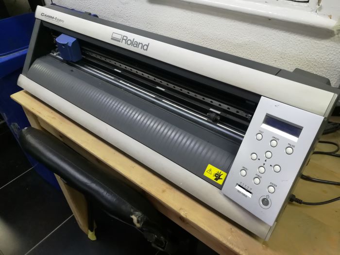
- The process of vinyl cutting starts with loading the vinyl roll from behind
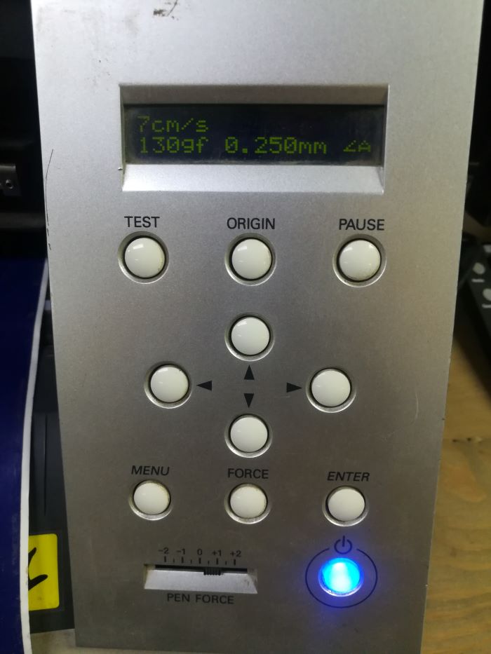
- Then, I set the cutting force to 135 and cutting speed to 7 cm/s
- To tranfer the Minion design to the vinyl cutter, I imported my design into Cut Studio Software
- Left click on the imported design, a window will open, then click extract image outline, then extract contour lines
- The extracted contour is what the vinyl machine follows, so I moved the contour in an empty space, deleted the imported design and moved the contour to the original position on the grid
- Finally, I chose file>> cutting>> ok
- After the vinyl cutting machine finishes the cutting process, I apply tape on the surface of the cut area then I peel it very slowly.
- The entire cut area is now stuck to the surface of the tape
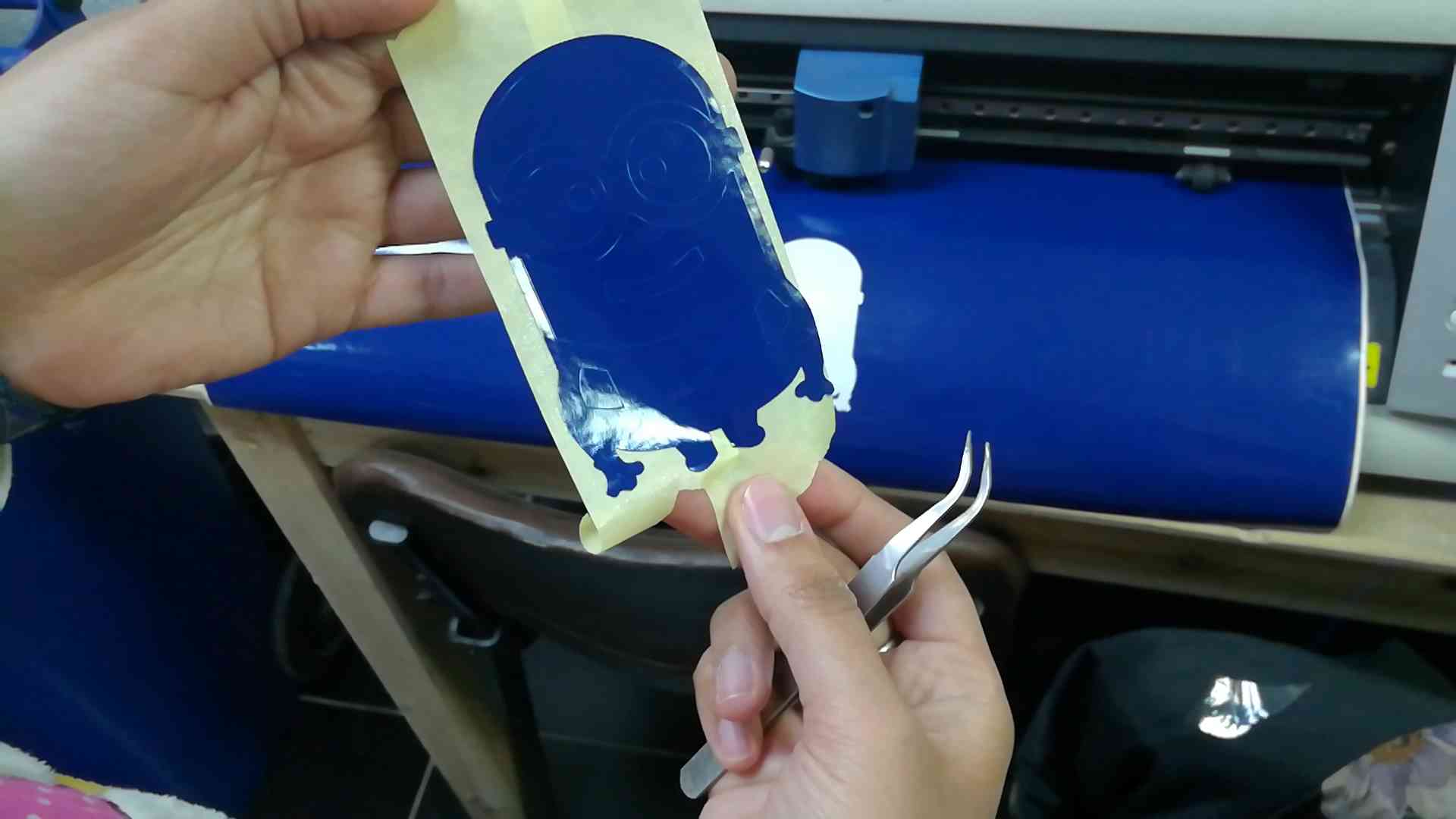
- Using a pair of tweezers, I started peeling away the extra pieces of vinyl
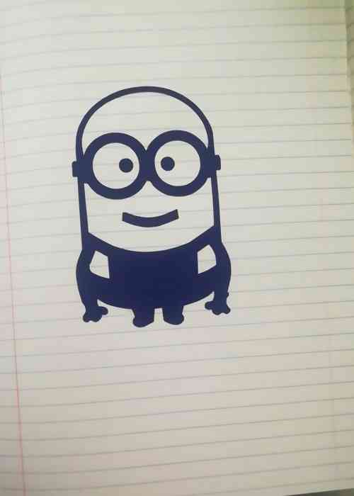
- Finally, I stick the tape with the cut design on any surface I like, I chose to apply it on the paper surface inside my note book
- Slowly, peelled the tape away leaving the cut design on the paper
3. Press-fit Construction Kit (Individual Assignment)
3.1 Computer-Aided Design
- I designed construction kit using Fusion 360, the kit contains 5 different pieces.
My design is entirely parametric and I accounted for the laser kerf which is 0.1 mm
- The first piece is a rectangular piece, with male-male, female-female and male-female version
- To tranfer the Minion design to the vinyl cutter, I imported my design into Cut Studio Software
- The second piece is a circle:
- The third piece is a triangle:
- The fourth piece is a trapizoid:
- And finally, another smaller rectangular piece that have female-female and male-female versions:
3.2 Fabrication using Laser Cutting Machine
- I imported the files into LaserWorks, I set the power to 75% and speed to 12 mm/s
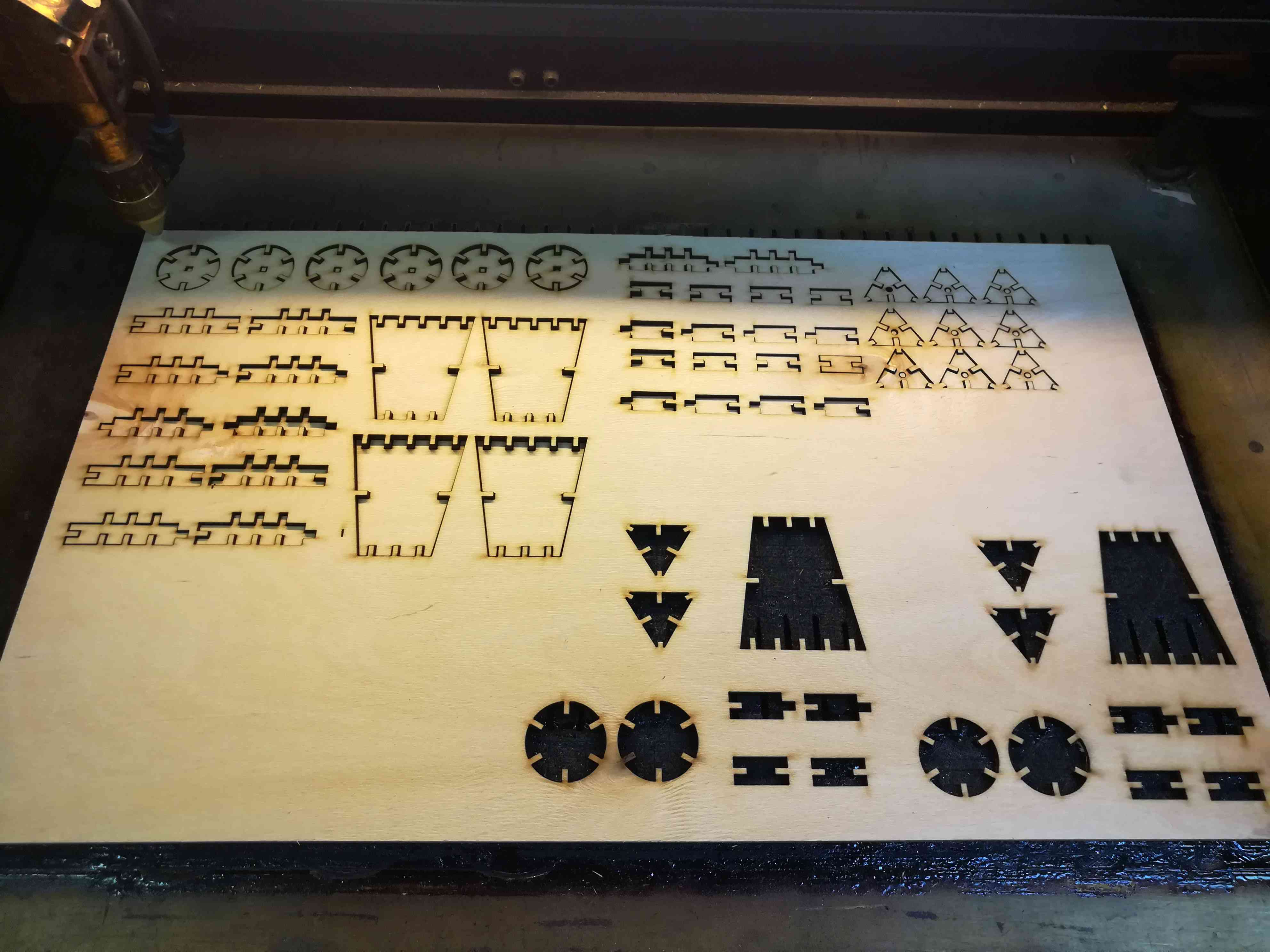
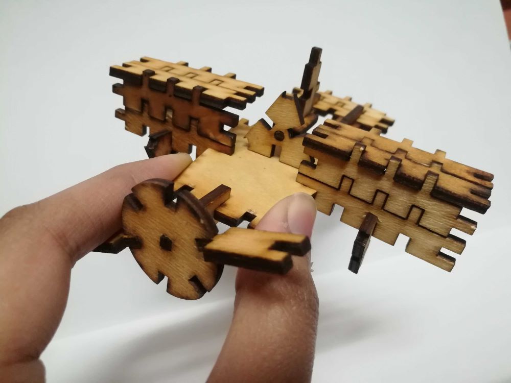
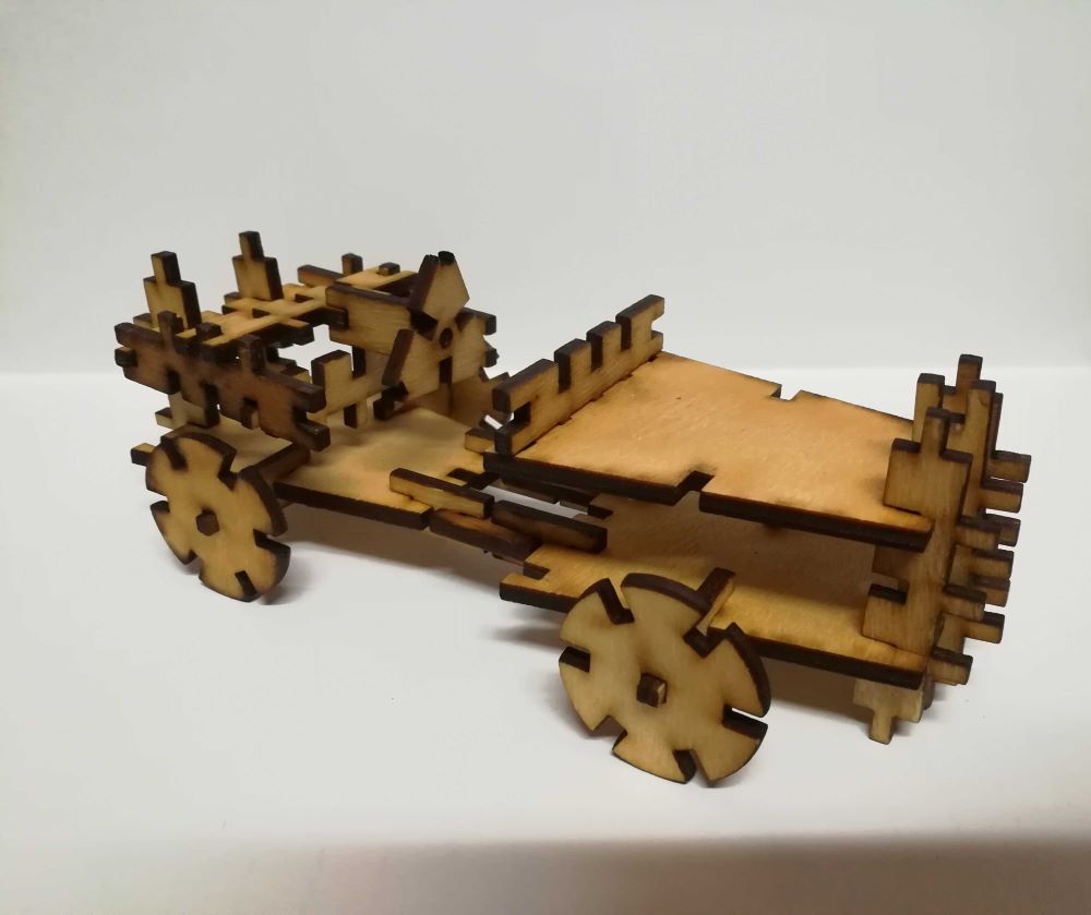
- I used to play with LEGOs and Meccano as a kid, so assembling the kit was the most amusing part to me!
I assembled the kit into 2 objects, an airplane and a sports car.
Design Files
Part 1
Part 2
Part 3
Part 4
minion.svg
Kit Parts Fusion 360 File