Networking & Communication Week 14
Introduction
For this week, we had two main tasks:
- Design, build, and connect wired or wireless node(s) with network or bus addresses
- Send a message between two projects
Design and connect node(s) with network or bus
Design and fabrication
- I used Autodesk Eagle to design the board. I first developed the board schematic, then switched to board view to route the board and connect the components.
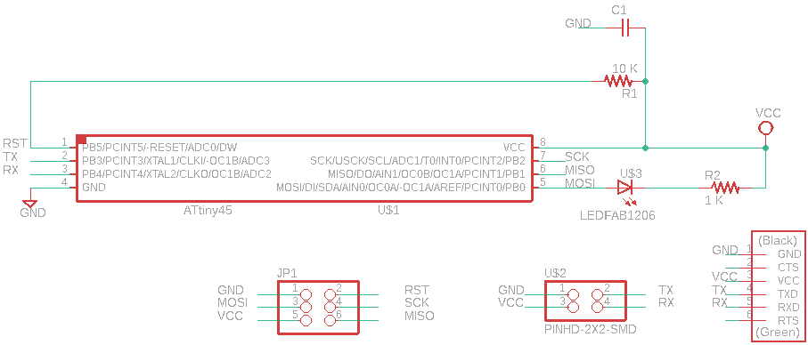
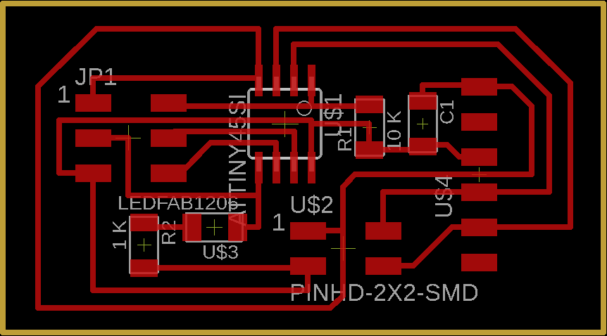
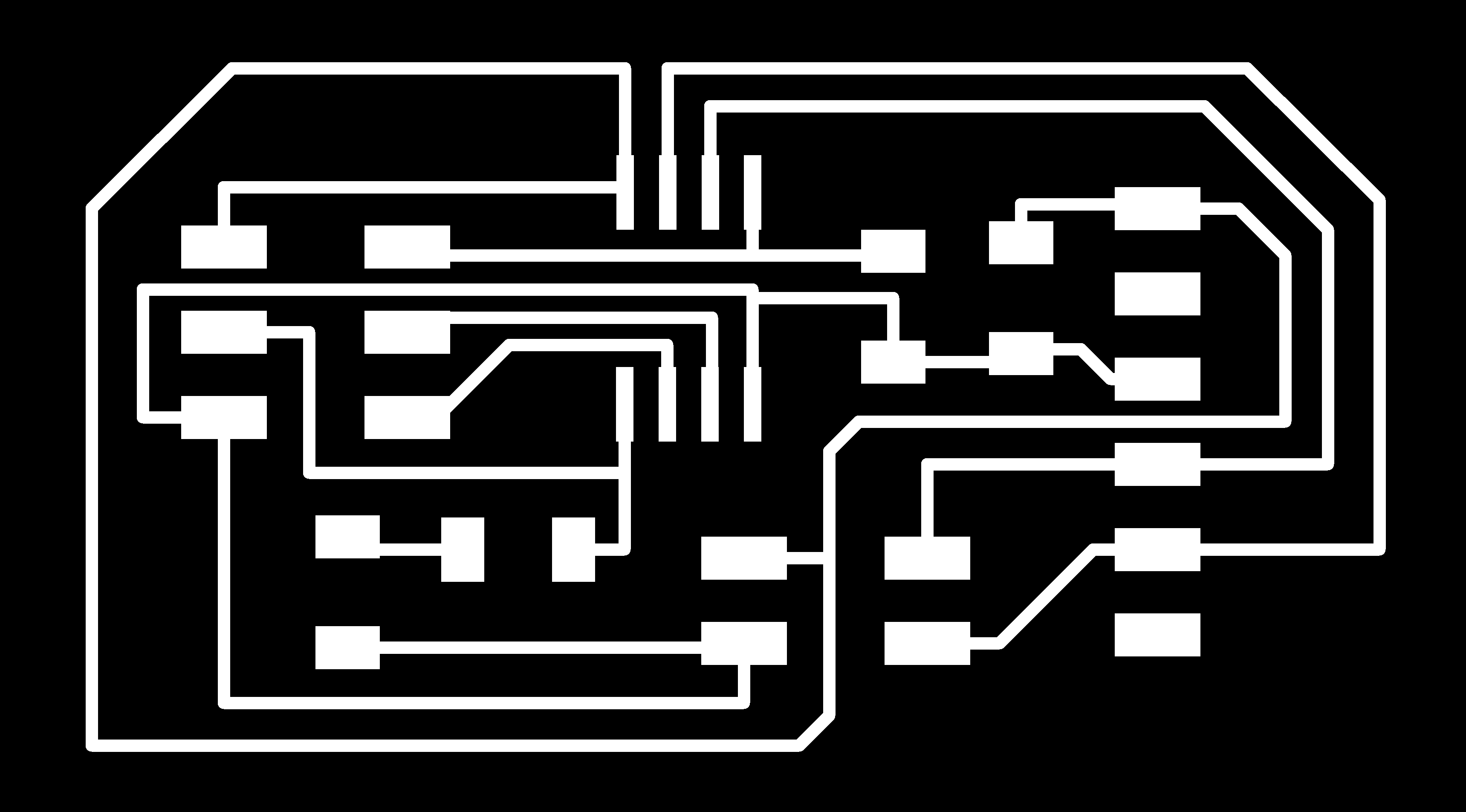
- Afterwards, I exported board's traces and frame as a monochrome image for milling.

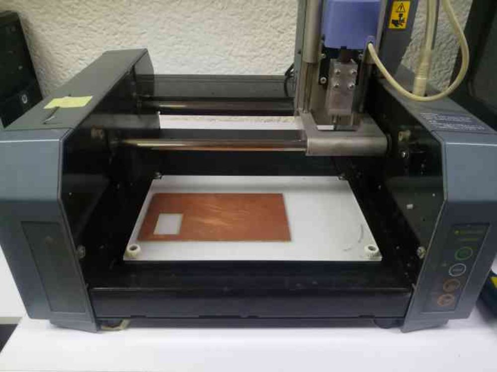
- TheN, I placed a PCB plate in Modela MDX-20, and installed the 1/64 milling tool to mill the traces.
- I imported the board images into Fabmodules and calculated the milling bit's toolpath. I did the same to mill the frame and cut out the board.
- I made a mistake while excuting the frame toolpath, as I set the offset at 4! which led the milling bit to cut part of a trace on the edge of the board. But I used an Avometer to make sure that the trace is fuctional and it was fine. So, I proceed with soldering the board.
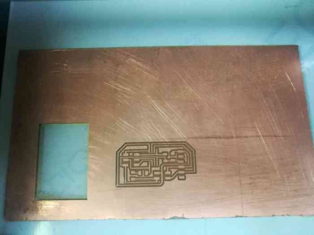
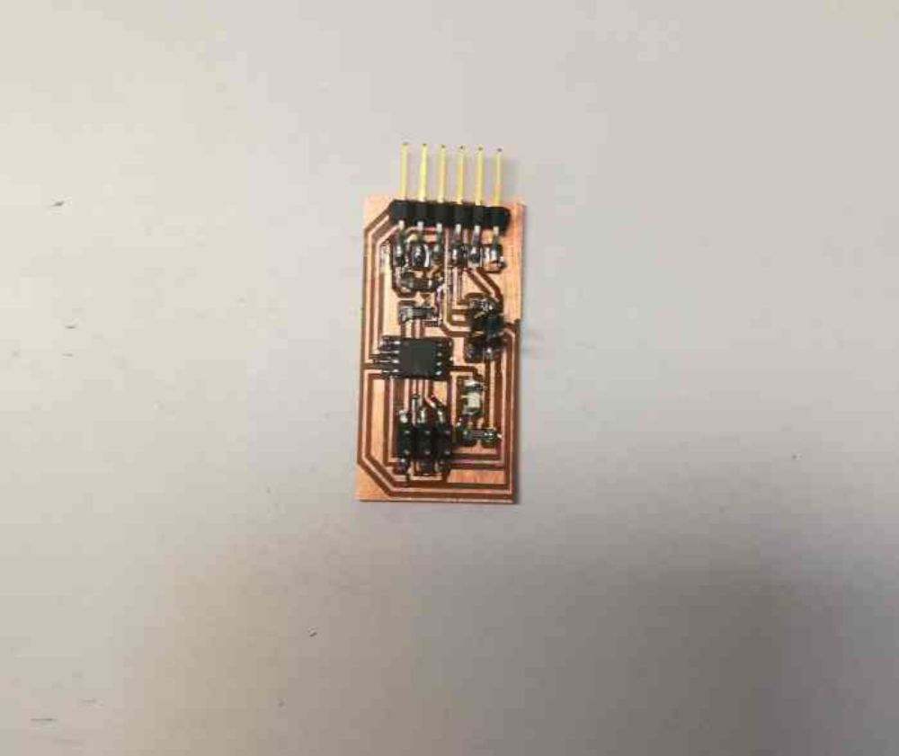
- So, "Node 1" was successfully soldered and was ready for programming.
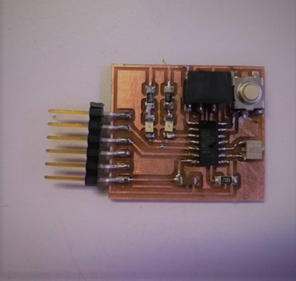
- For "Node 2", I reused the hello echo board from the electronics design week, I incorporated LEDs into the design of the board in that week, whick I will use later for node testing in this week's assignment.
Programming: Failed Attempt
- I started with trying to program "Node 1". I used FABISB to upload the code into the board and the uploading was successful.
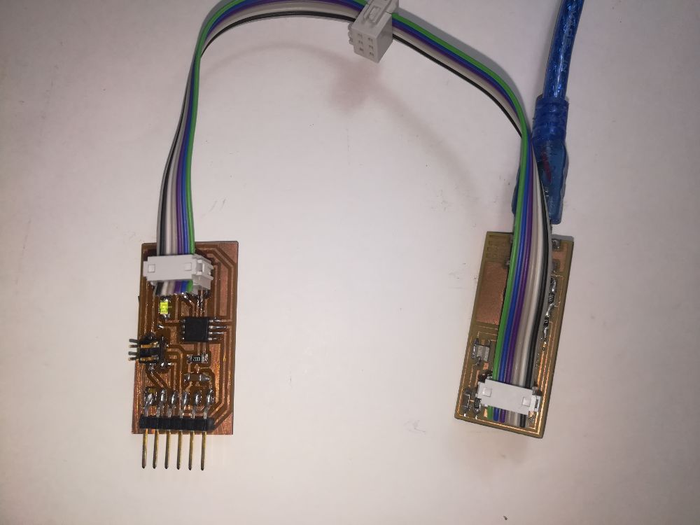
- The node's code utilizes the software serial library to perform serial communication. The board listens for any incomming data at the RX pin of the Attiny 45 chip, and whenever it "hears" a certain character (5 in this case) that simulates the nodes "address", it flashes it the LED and prints a message on the serial monitor.
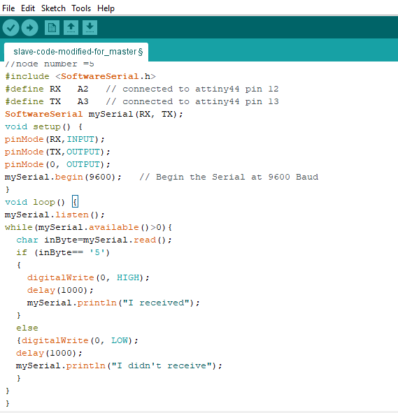
- I connected the board afterwards to through the FTDI cable to the computer, but my trials to communicate serially with the board has failed. I revised all my conncetions serveral times, including soldering, but no luck!
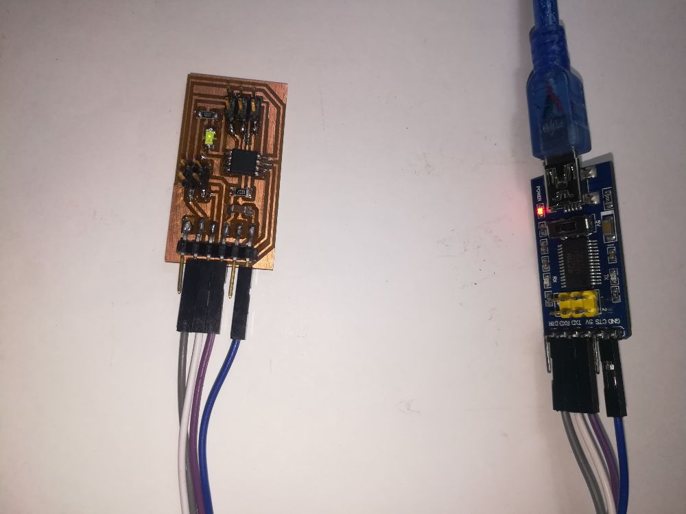
- I needed to make sure that the code works, so I uploaded the same code to the second node, just changed the TX, RX and LED pins, and worked perfectly! Thus, I had my doubts was directed towards the ATT45 chip, either it is simply not functional or that attiny 45 simply doesn't work well with serial software library, which I doubted because I used serial communciation in the input devices week, and I used attiny 45 as an MCU and it worked perfectly.
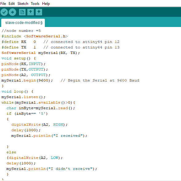
Programming: Successful Attempt
- I decided to go ahead and test my theory, I brought the same board I designed and fabricated for the input devices week, the color sensor board, and decided to use it as "Node 1".
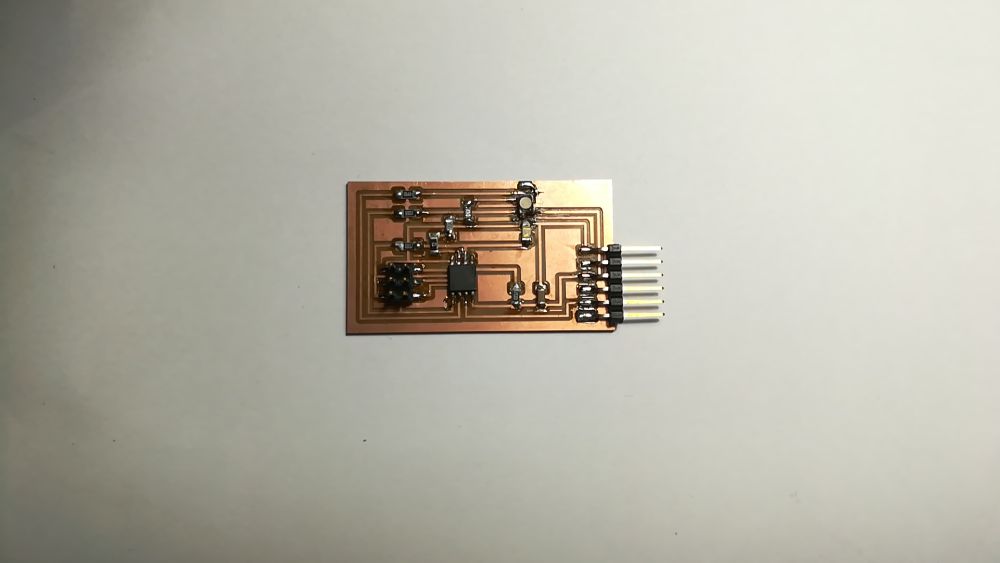
- But I had a challenge, when I designed this board I only connected a TX pin to the FTDI pin header. So, I decided two reconfigure the MOSI and SCK pins to be RX and TX repectively. Using attiny45 pinout diagram, I mapped pins 6/7 (MOSI/SCK) to pins (1/2) on the Arduino.
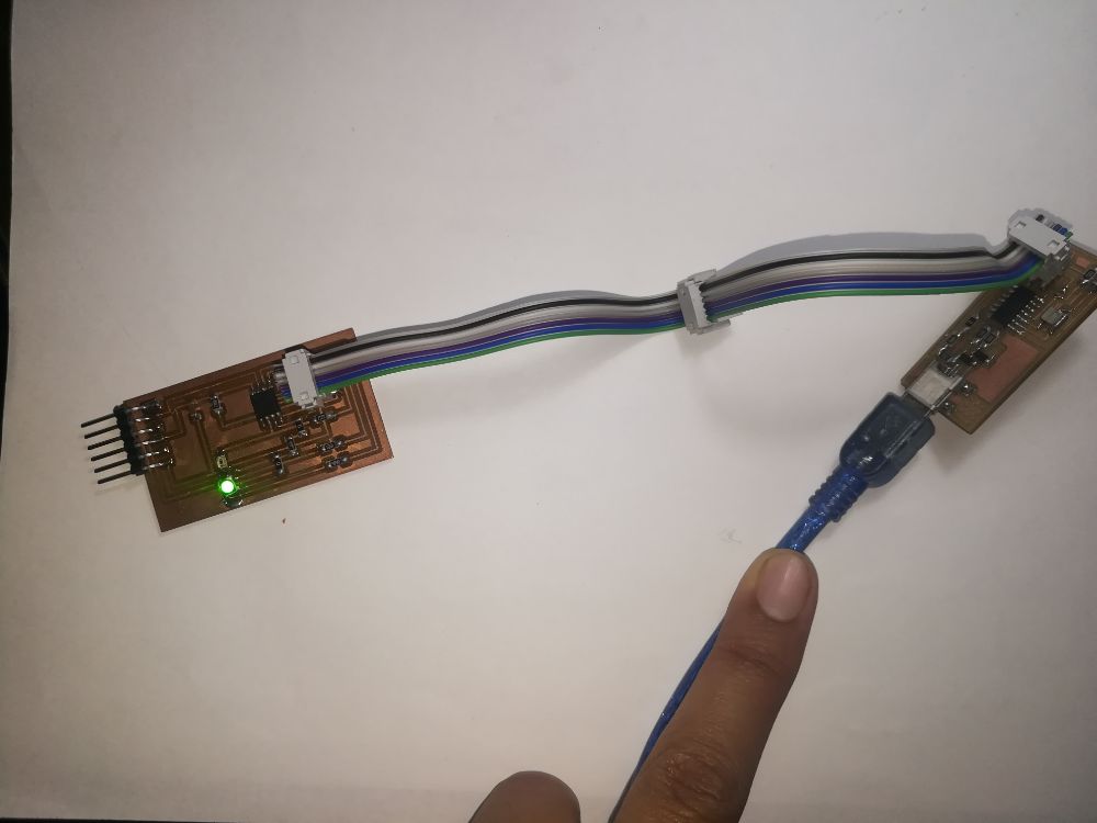
- I defined an ID of value "1" for this board, when the board "hears" its number, the RGB LED on board will flash in green and red colors, and sends a confirmation message.
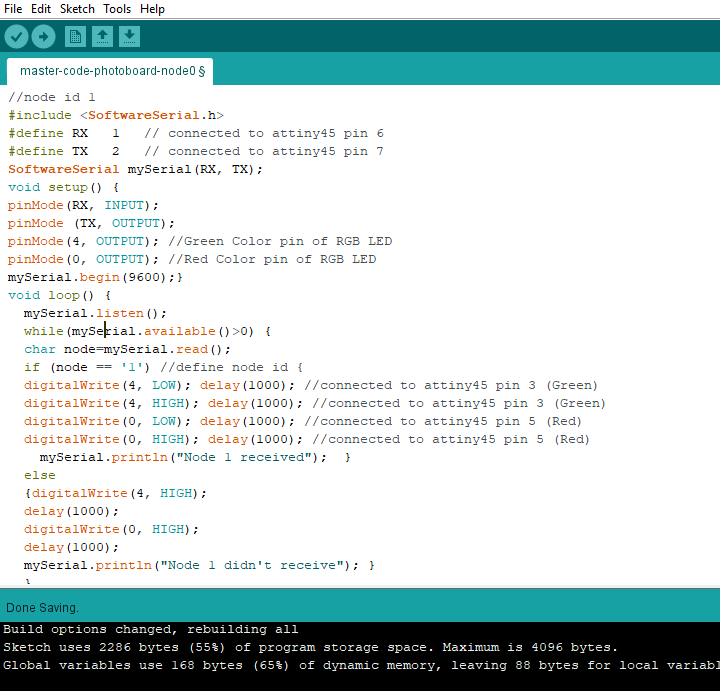
- The code was uploaded successfully, and now came the moment of truth, will it work? I connected the TX, RX, VCC and GND pinheaders to the FTDI's corresponding pins.
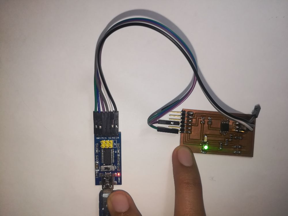
- It worked perfectly! Thus, I believe the problem was in the particular attiny45 chip that I used for the first board. Here is a demo video of node 1 communicating serially:
- Node 1:
- I went ahead and programmed node 2 as well.
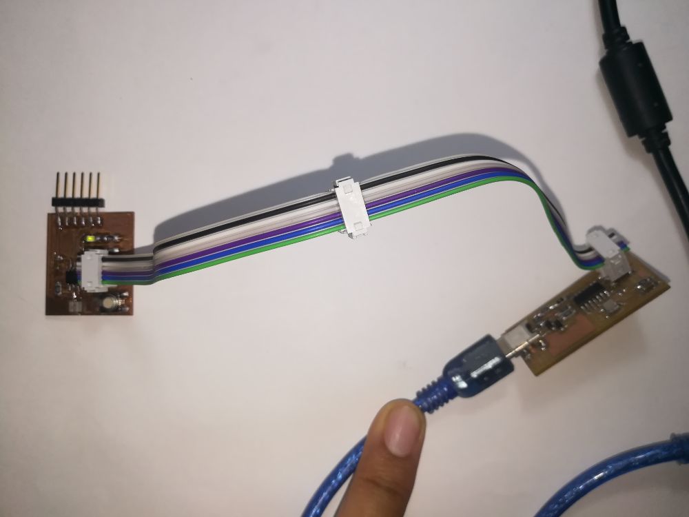
- I defined an ID of "2" for this board, when the board listens its ID, the LED on board will turn off and send a confirmation message.
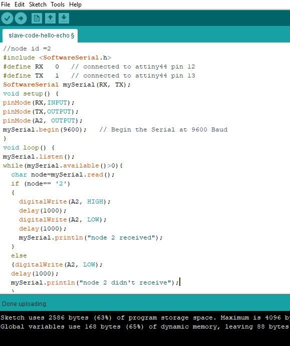
- The communication went will with node 2, here is a demo of node 2 communicating serially:
- Now, I needed to connect the two boards with a shared bus, but when I designed the boards I didn't account for bus pinheaders. The original node "1" design incorporated a pinheader for the bus, this is how the bus should look like, if the board was functional:
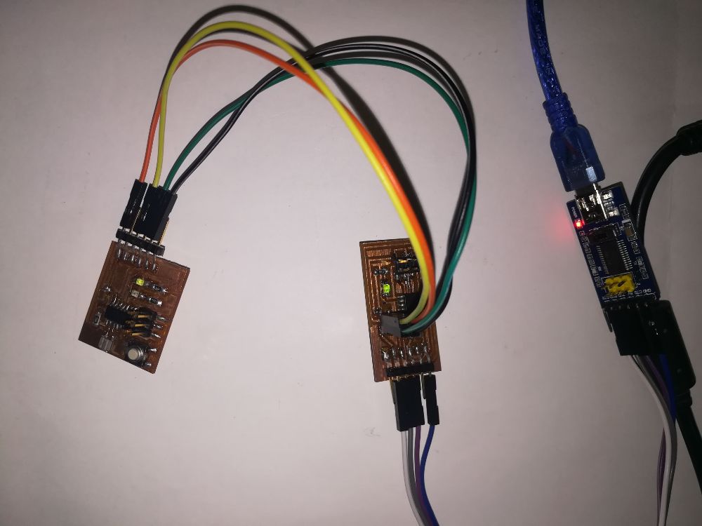
- And this is how I decided to improvise! I used a bread board to make the bus connections.
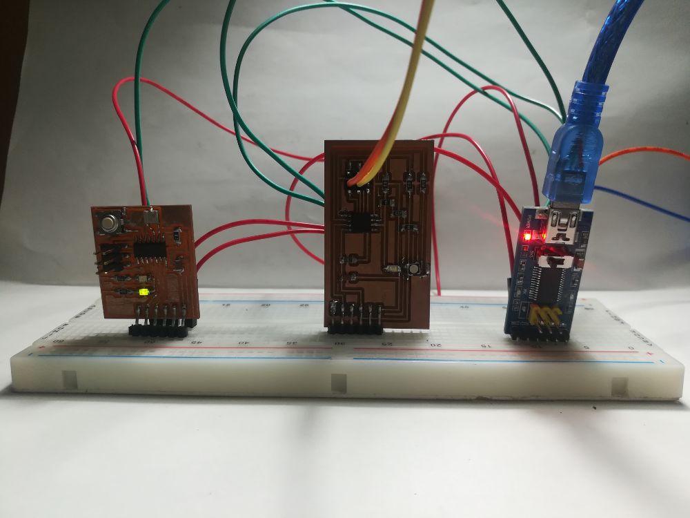
- I opened the serial monitor on Arduino IDE and started testing the addressing and it worked very well. Here is a demo video:
- Node 1 & 2:
- Except, I noticed that the nodes stopped sending the confirmation messages to the serial monitor. I suspect that the problem here is that both nodes are sending messages at the same time on the bus, for example, node 1 is sending a confirmation message and node 2 is sending a decline message, which can't happen in the same time I guess on the same line.
Design Files