Electronics Design Week #7
Introduction
This week we have three main assignments:
- Redraw the echo hello-world board, add (at least) a button and LED (with current-limiting resistor)
- Check the design rules, make it, and test it
- Use the test equipment in your lab to observe the operation of a microcontroller circuit board
1. Redraw the echo hello-world board (Individual Assignment)
- I chose to use Autodesk Eagle software to design my board for this week.
- I started with adding the Fab inventory library to Eagle, then I created a new project, and inside the project I created a new schematic.
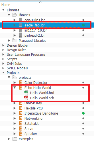
- I started with adding the components of the echo hello-world board from the eaglefab library. The needed components for the board are: Attiny 44, 1uF capacitor, 10K resistor, 20MHz resonator, 2x3 pin header, and FTDI pin header.
- After adding the components, I started connecting them, by clicking on the net icon from the bar on the left, then simply use the mouse to connect the two desired points.
- To save the time and effort of wiring every single pin, I used labels. For example, I will need to connect the Reset pin of the Attiny 44 with the FTDI header. So instead of connecting them by a Net, I label both pins and give them the same name "RST".
- I will follow the labelling technique from the previous step to wire the 2x3 pin header and the FTDI pin header to their corresponding pins on the ATTiny 44
- Now that I finished connecting all the components in the schematic, I will now switch to the board.
- I started with laying out the components on the desired position on the board, by simpy clicking on and draging them to their new position
- After placing the components, I wired them by clicking the route icon on the left bar.
- After finishing routing the basic echo hello-world board, I went back to the schematic to add a button, 2 LEDs, and 2 current limmiting resistors
- I needed to calculate the current limiting resistor's value, I used the equation R= (Vs-Vf)/I, Where Vs is the supply voltage (5 V), Vf is the LED forward drop voltage (2.1 v according to the LED's datasheet), and I is the LED forward current (20 mA according to the LED's datasheet). Thus, R= (5-2.1)/0.02= 145 ohms. The lowest available resistor in our inventory is 499 ohms, which works fine too even though the LED's light will be a little bit dimmer because the voltage drop around it will be less.
- I connected the button to the PA7 pin of the Attiny 44, and the two LEDs on the PA2 and PA3 pins.
- I connected the two LEDs to the VCC, considering that it is the closest power line on the board.
- Finally, the board is done!
2. Check the design rules, make it, and test it
- Now I need to check if the board aligns with the design rules of Fabmodules. So, I click on Tools, then DRC.
- A window will open, I will click on Load, then I will choose the Fabmodules design rules file.
- Finally, I will click the Check button below, to see if there is any errors with board. There was no errors.
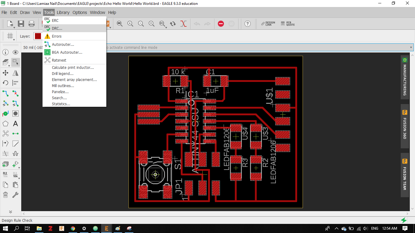
- Now, I can proceed to exporting my board for fabriction. I have two images that I need to export, the traces and the cutting frame.
- I click on the layers setting icon, hide all the layers, then show only the top layer (the traces).
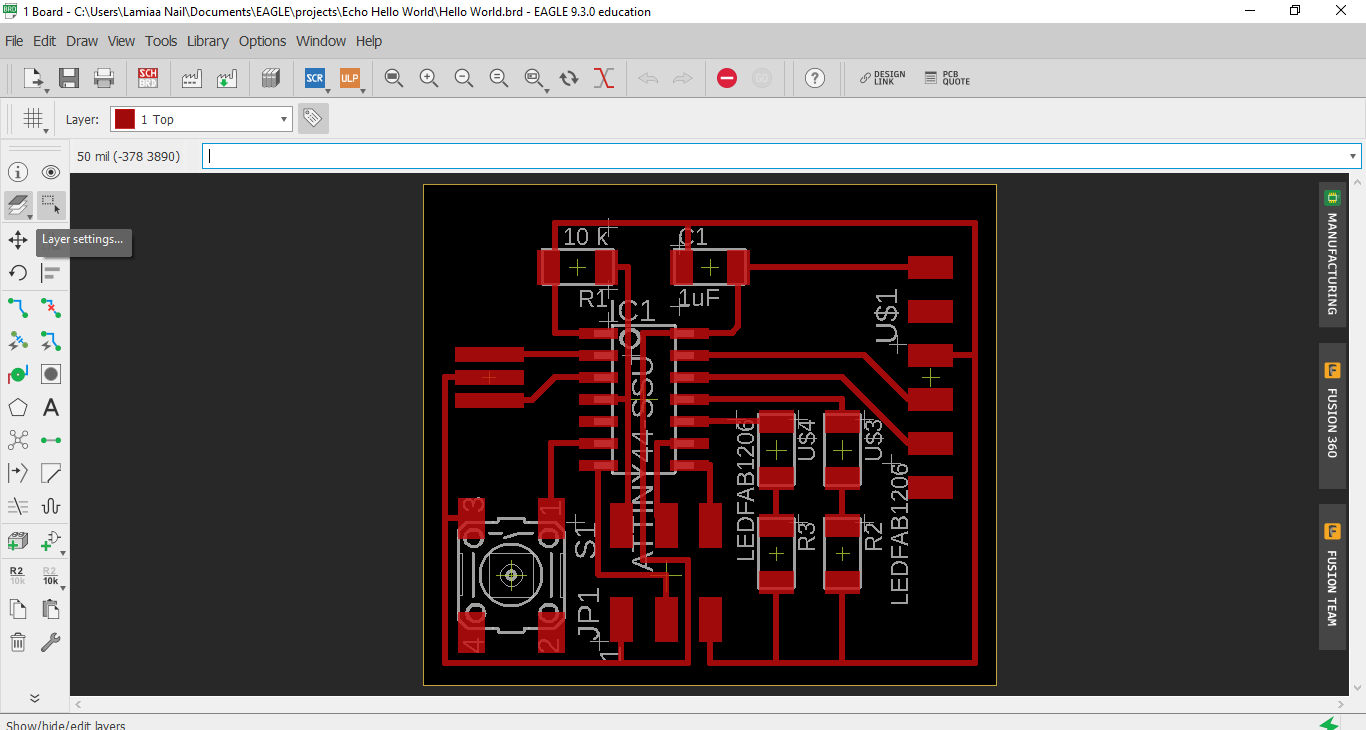
- Then, I check the monochrome box, and set the resolution to a number tha exceed 700 dbi to make sure that Fabmodules can detect the traces, finally click the export button.
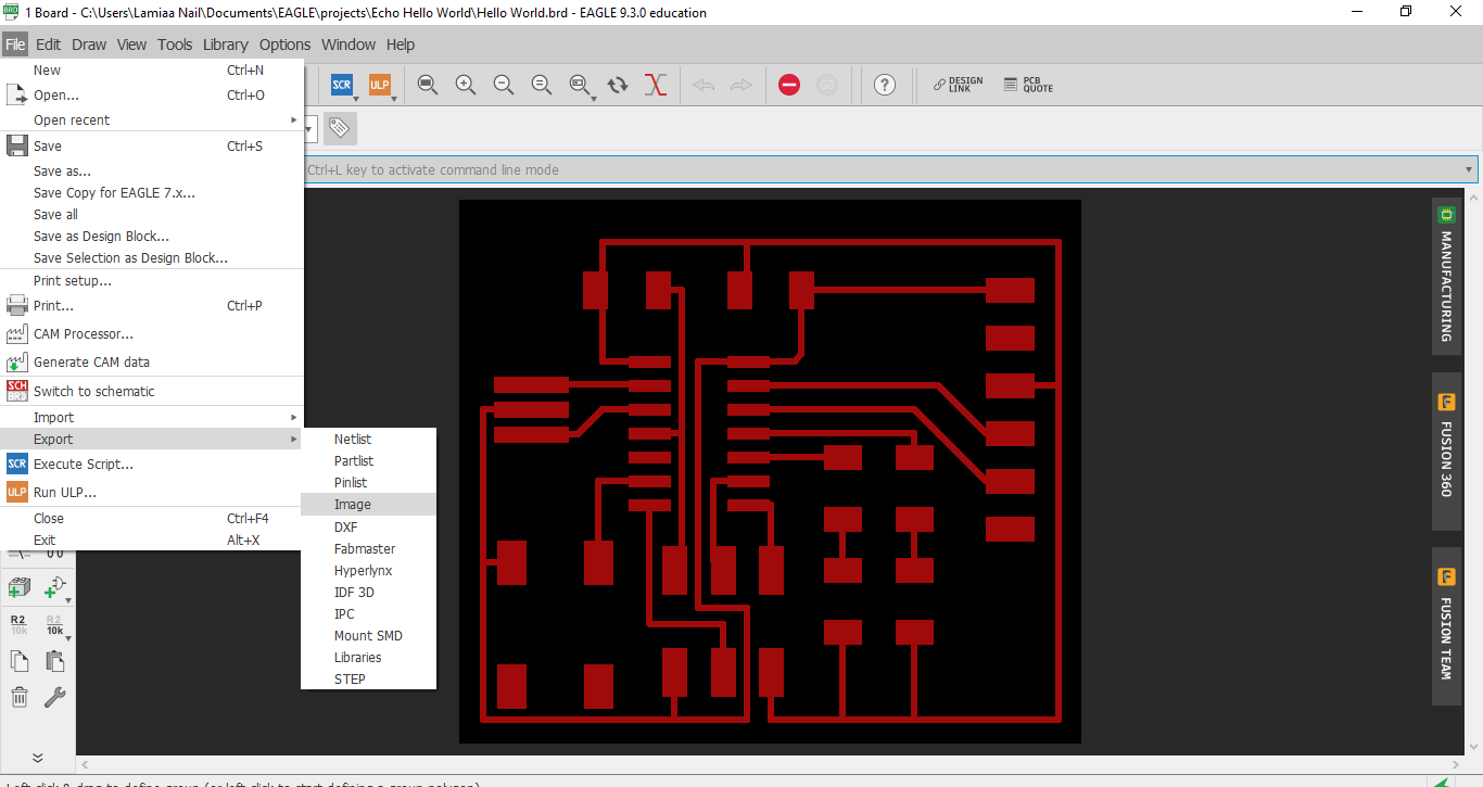
- I will repeat the previous two steps to export the cutting frame image. But this time I will hide all the layers and only show the Dimension layer.
- Now the traces and the frame are ready to be imported into Fabmodules for fabrication
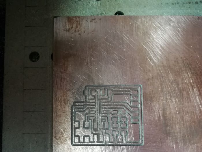
- I imported the traces image, chose the machine, calculated the toolpath and finally sent it to the Modela.
- The traces were milled successfully
- Afterwards, I imported the cutting frame image, calculated the toolpath and sent to the machine to cut the board
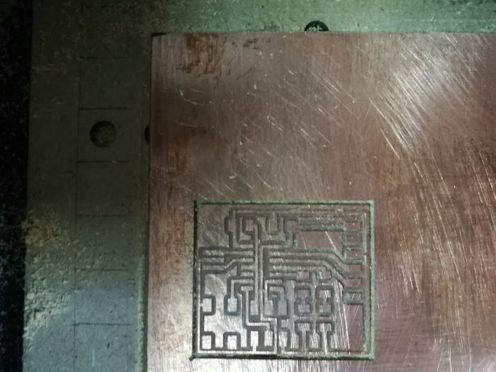
- Now the board is ready for soldering!
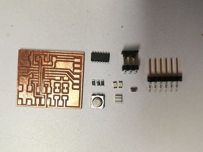
- The final board
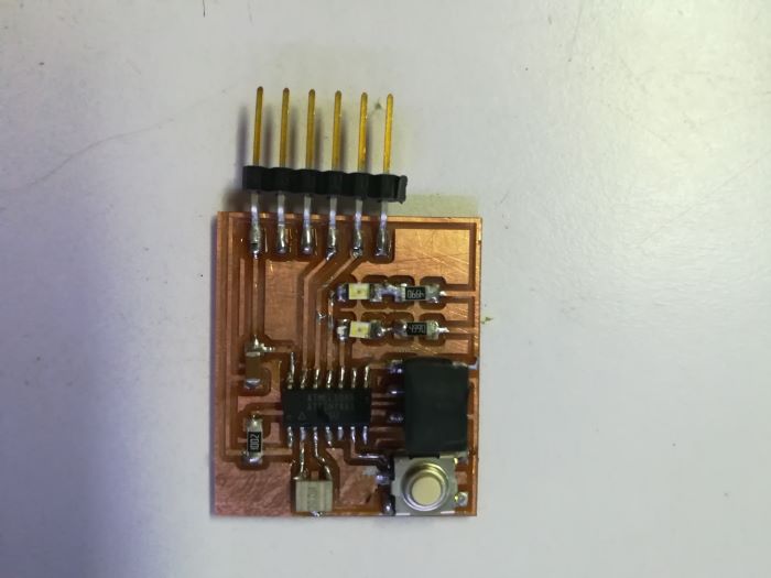
3. Observe operations of microcontroller (Group Assignment)
- We actually did this task in the output devices week, as it was necessary for us to understand the concept of PWM, and how it is visualized using the Oscilliscope.
- For this purpose, We hooked the servo board to the oscilliscope, connecting the signal pin and ground.
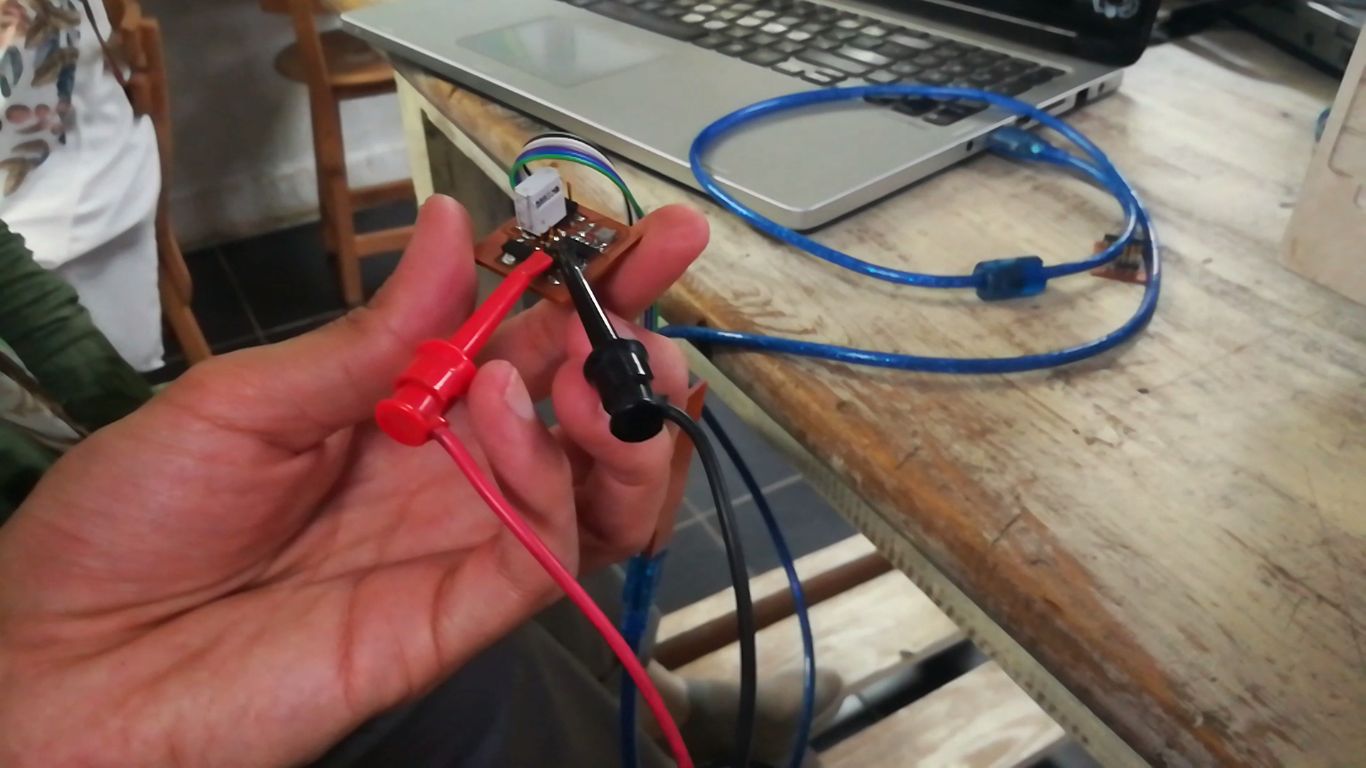
- We pre-programmed the board to output a PWM of 1, 1.5 and 2 ms, corresponding to 0, 90 and 180 degrees on the servo motor.
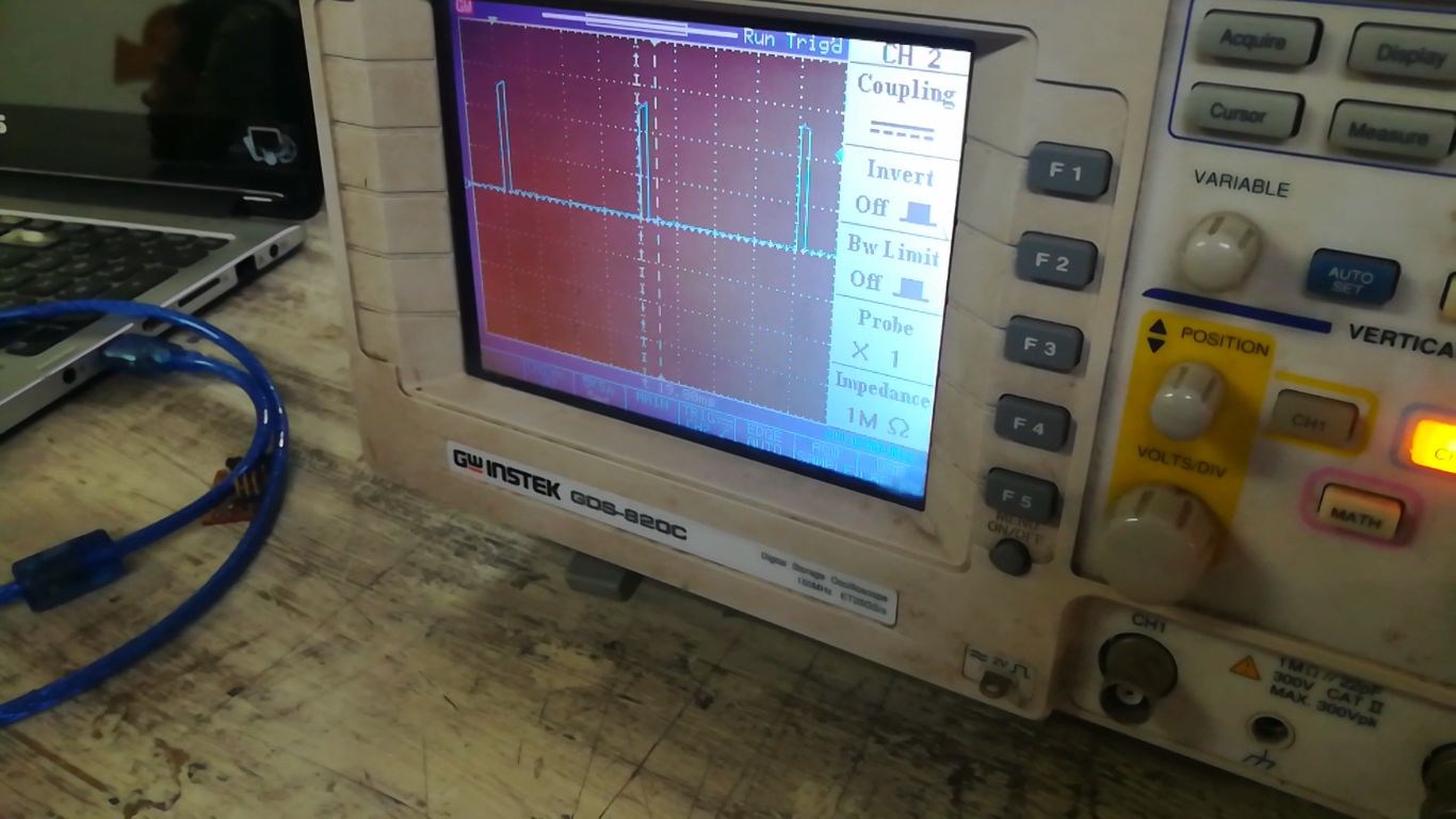
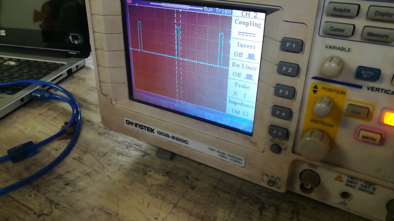
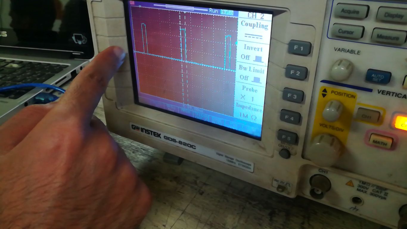
- Observing the PWM values on the screen, we noticed how the width of the signal wave changes from 1 to 1.5 to 2 ms, which was amazing to actually see it in action!
- PWM of 1 ms
- PWM of 1.5 ms
- PWM of 2 ms
Design Files
- Then, I check the monochrome box, and set the resolution to a number tha exceed 700 dbi to make sure that Fabmodules can detect the traces, finally click the export button.