Embedded Programming Week #9
Introduction
This week we have three main assignments:
- Read a microcontroller data sheet
- Program your board to do something
- Compare the performance and development workflows for other architectures
Read a microcontroller data sheet
- I used to use datasheets as an engineering student, however, the Atmel datasheet is way complicated. So, I started from the basics, and for this purpose I used the Make: AVR programming book and I found its approach very simple.
- There is an important quotation that stuck with me from the book: "The trick is to approach the datasheet like a reference book rather than a novel".
- I followed this advice and tried to have some questions in mind that I can use the datasheet as a reference to answer. With the help of the documentation of Adhitya, a previous Fab Academy student, I chose to answer 2 essential questions through reading the data sheet of the ATMEL AVR datasheet:
- What are the microcontroller's capabilities and how to use them optimally?
- What and how can I connect my devices to this microcontroller?
- Question 1: I went through the datasheet to answer the first question and found that the features page answer it briefly while datasheet dedicates entire sections to detail each of these features.
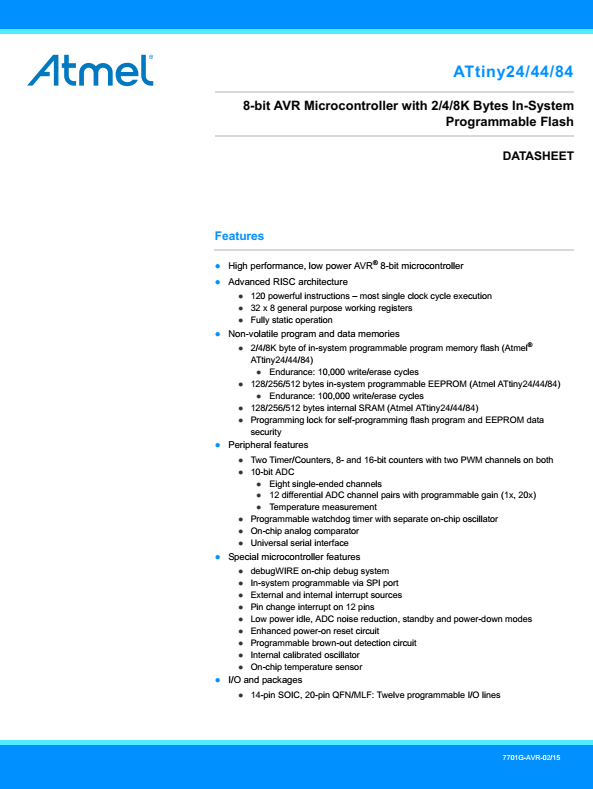
- Three important features to attend to while reading a datasheet are the memory, clocks and input and output ports:
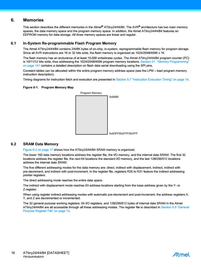
- Memory: the datasheet describes the memory capabilities of the microcontroller, describing three types of memory: the flash memory is where the compiled program is stored, the RAM where temporary variables are stored, and the EEPROM where data can be stored and it won't be lost when the power goes out.
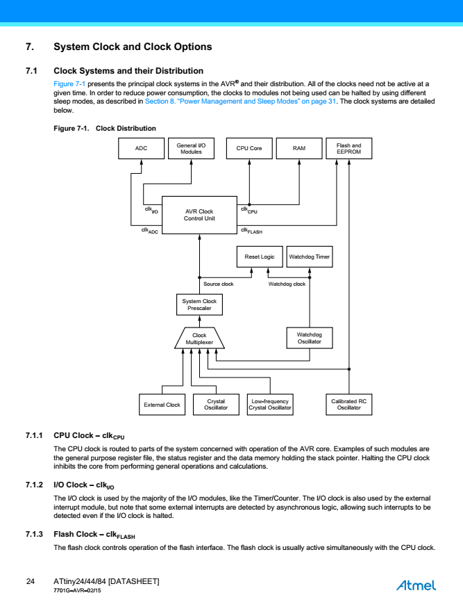
- Clocks: the datasheet describes different types of clocks that drive the microcontroller's operations. For example, the CPU clock is concerned with the operation of the core. There are other clocks that times the operations of the I/O, ADC and flash memory.
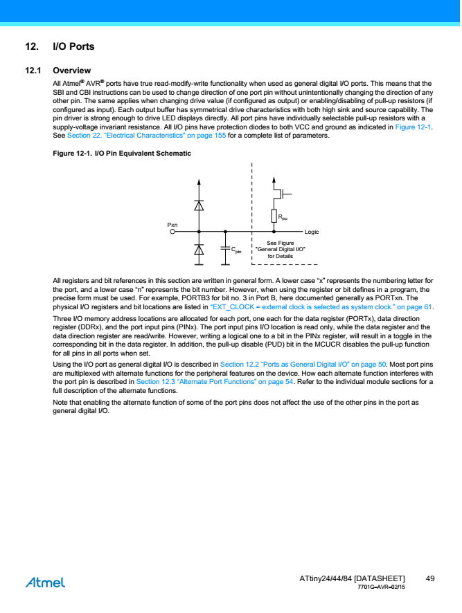
- Outputs and Inputs (I/O): this section of the data sheet describes the ports that allow the AVR microcontroller to: "speak" with outside world (through output ports) and "listen" to incoming signal (through input ports).
- Memory: the datasheet describes the memory capabilities of the microcontroller, describing three types of memory: the flash memory is where the compiled program is stored, the RAM where temporary variables are stored, and the EEPROM where data can be stored and it won't be lost when the power goes out.
- Question 2: This question can be answerd by looking into the pin conficguration section of the datasheet. This section comes in handy while planning the schematic and board design.

Program your board to do something
- For this assignement, I chose Arduino C as the programming language. I downloaded and installed Arduino IDE to program the board.
- Before starting programming, I have to add the ATTiny 44 board for Arduino IDE to recognize it. I click Tools>>>Board>>>Boards Manager, to add it from an external library.
- I copied this link to ATTiny library: https://raw.githubusercontent.com/damellis/attiny/ide-1.6.x-boards-manager/package_damellis_attiny_index.json
- I added the link in the boards' manager window, selected the ATTiny board library, and installed it.
- Now, I can easily go to tools>>>boards and select ATtiny 24/44/84 from the bottom of the list.
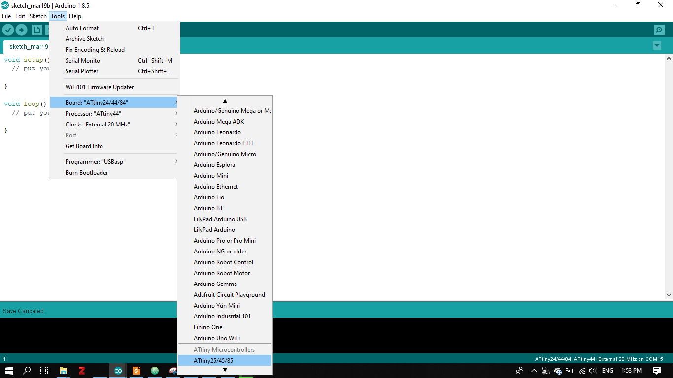
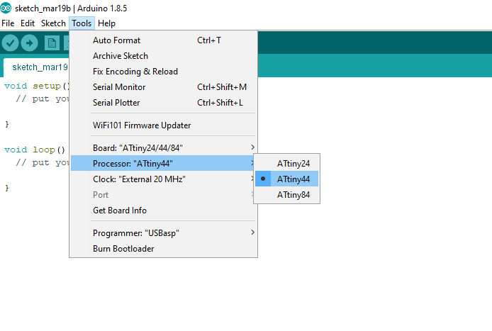
- I also chose the processor to be ATtiny 24/44/84
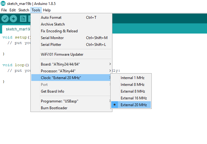
- Finally, I set the clock to an external clock at 20 MHz.
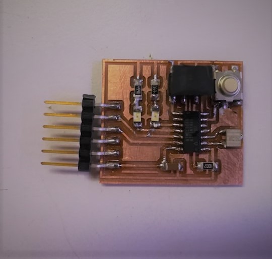
- For the programming assignement I used the hello echo board that I fabricated for the electronics design week. In my design, I modified the board to include 2 LEDs and a button.
Button Blink Program
- I worked on two programs for this boards. First, I programmed the board to blink the two LEDs alternatively when the button is clicked.
- Before starting the programming, I had to use the pinout diagram that maps the ATtiny's pins to the Arduino board pins.

- I mapped the ATtiny 44's pins PA2 & PA3 which are connected to the LEDs and pin PA7 which is connected to the button, to pins A2, A3 & A7 on the Arduino board, respectively.
- I configured the pinmode of each of the these pins as output in the case of the LEDs. For the button, the pinmode was set to an input_pullup, rather than, input only, to keep the pin from being float (picking up random voltage from the envirnoment)
- Then, I used an IF condition, to turn the LEDs on and off, one at a time, over and over again, as long as the button is pressed. Whereas, the else if condition, when the button is not pressed, the two LEDs return to their default status which is being lit, because they are both connected to a VCC power source.
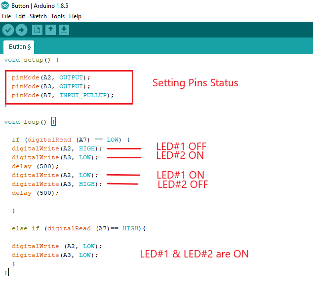
- Code:
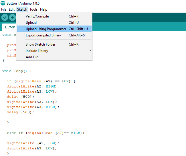
void setup() { pinMode(A2, OUTPUT); pinMode(A3, OUTPUT); pinMode(A7, INPUT_PULLUP); } void loop() { if (digitalRead (A7) == LOW) { digitalWrite(A2, HIGH); digitalWrite(A3, LOW); delay (500); digitalWrite(A2, LOW); digitalWrite(A3, HIGH); delay (500); } else if (digitalRead (A7)== HIGH){ digitalWrite (A2, LOW); digitalWrite(A3, LOW); } } - Finally, I uploaded the code on the hello echo board using the FABISP programmer.
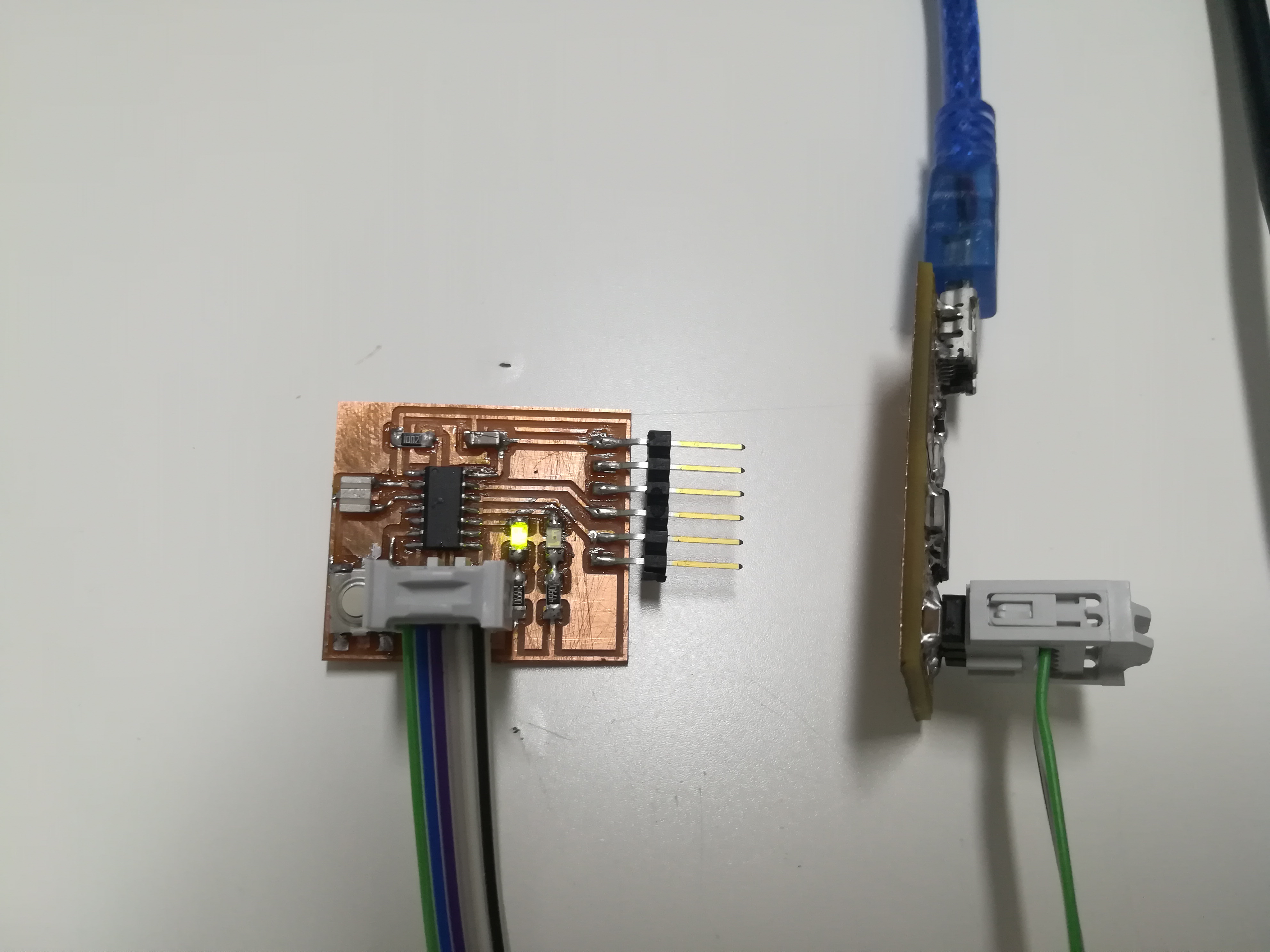
- Final outcome:
Morse Code Program
- For the second program, I thought I can to make use of the FTDI for communication. I had an idea to develop a code to translate English letters and numbers into visual morse code using the LEDs.
- My programming skills are not that high, so I decided to search for a simple code that I can use for this purpose. I found an simple and easy to understand code on Instructables for Arduino boards.
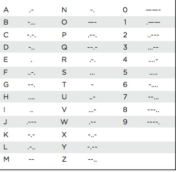
- A little background about morse code, it is composed of only two symbols which are dashs and dots. Each letter and number is a combination of dashs and dots as shown in the diagram below. Dashs and dots can be simply translated into visual or audio signal. In our case, they will be converted into light.
- I modified the code to suit the ATtiny 44 board.
- First, I included the SoftwareSerial library to be able to communicate with the board through the FTDI. I also mapped the Tx and Rx of the ATtiny 44 to A0 & A1 on the Arduino board using the pinout diagram.
- As in the blinking program, I set A2 AND A3 as outputs.
- The code for this program is simple, two functions are created for the dot and the dash, the dot function translate the dot to turing the LEDs ON for 3 ms and the dash function to turning the LEDs ON for a longer period of time which is 9 ms, for the observer to be able to differentiate between the dots and dashs.
- Also, Functions are created for each and every letter from A to Z and number from 1 to 10 as well. The letters and numbers functions call the dash and dot functions as shown in the morse code image shown above.
- Code:
#include <SoftwareSerial.h> SoftwareSerial mySerial (A0, A1); char input; // to save the input void setup () { pinMode (A2, OUTPUT); pinMode (A3, OUTPUT); mySerial.begin(9600); } void loop () { if (mySerial.available()) { input = mySerial.read();//read the input if (input == 'a' || input == 'A') {lA();}//if the input is a or A go to function lA if (input == 'b' || input == 'B') {lB();}//same but with b letter if (input == 'c' || input == 'C') {lC();} if (input == 'd' || input == 'D') {lD();} if (input == 'e' || input == 'E') {lE();} if (input == 'f' || input == 'F') {lF();} if (input == 'g' || input == 'G') {lG();} if (input == 'h' || input == 'H') {lH();} if (input == 'i' || input == 'I') {lI();} if (input == 'j' || input == 'J') {lJ();} if (input == 'k' || input == 'K') {lK();} if (input == 'l' || input == 'L') {lL();} if (input == 'm' || input == 'M') {lM();} if (input == 'n' || input == 'N') {lN();} if (input == 'o' || input == 'O') {lO();} if (input == 'p' || input == 'P') {lP();} if (input == 'q' || input == 'Q') {lQ();} if (input == 'r' || input == 'R') {lR();} if (input == 's' || input == 'S') {lS();} if (input == 't' || input == 'T') {lT();} if (input == 'u' || input == 'U') {lU();} if (input == 'v' || input == 'V') {lV();} if (input == 'w' || input == 'W') {lW();} if (input == 'x' || input == 'X') {lX();} if (input == 'y' || input == 'Y') {lY();} if (input == 'z' || input == 'Z') {lZ();} if (input == '1') {n1();}// the numbers if (input == '2') {n2();} if (input == '3') {n3();} if (input == '4') {n4();} if (input == '5') {n5();} if (input == '6') {n6();} if (input == '7') {n7();} if (input == '8') {n8();} if (input == '9') {n9();} if (input == '0') {n0();} if (input == ' ') {space();}//the space mySerial.println (input);//print the latter saved in the input var } } //functions for the letters and the numbers void lA () {dot();dash();shortspace();}//letter A in morse code! void lB () {dash();dot();dot();dot();shortspace();}//same for B void lC () {dash();dot();dash();dot();shortspace();} void lD () {dash();dot();dot();shortspace();} void lE () {dot();shortspace();} void lF () {dot();dot();dash();dot();shortspace();} void lG () {dash();dash();dot();shortspace();} void lH () {dot();dot();dot();dot();shortspace();} void lI () {dot();dot();shortspace();} void lJ () {dot();dash();dash();dash();shortspace();} void lK () {dash();dot();dash();shortspace();} void lL () {dot();dash();dot();dot();shortspace();} void lM () {dash();dash();shortspace();} void lN () {dash();dot();shortspace();} void lO () {dash();dash();dash();shortspace();} void lP () {dot();dash();dash();dot();shortspace();} void lQ () {dash();dash();dot();dash();shortspace();} void lR () {dot();dash();dot();shortspace();} void lS () {dot();dot();dot();shortspace();} void lT () {dash();shortspace();} void lU () {dot();dot();dash();shortspace();} void lV () {dot();dot();dot();dash();shortspace();} void lW () {dot();dash();dash();shortspace();} void lX () {dash();dot();dot();dash();shortspace();} void lY () {dash();dot();dash();dash();shortspace();} void lZ () {dash();dash();dot();dot();shortspace();} void n1 () {dot();dash();dash();dash();dash();shortspace();}//number 1 in morse code void n2 () {dot();dot();dash();dash();dash();shortspace();} void n3 () {dot();dot();dot();dash();dash();shortspace();} void n4 () {dot();dot();dot();dot();dash();shortspace();} void n5 () {dot();dot();dot();dot();dot();shortspace();} void n6 () {dash();dot();dot();dot();dot();shortspace();} void n7 () {dash();dash();dot();dot();dot();shortspace();} void n8 () {dash();dash();dash();dot();dot();shortspace();} void n9 () {dash();dash();dash();dash();dot();shortspace();} void n0 () {dash();dash();dash();dash();dash();shortspace();} void space () {delay (1200);}//space between words void dot () {digitalWrite(A2,HIGH); digitalWrite(A3,HIGH); delay (300); digitalWrite(A2,LOW); digitalWrite(A3,LOW); delay (300);}//the dot this code make the led on for 300 than off for 300 void dash () {digitalWrite(A2,HIGH); digitalWrite(A3,HIGH); delay (900); digitalWrite(A2,LOW); digitalWrite(A3,LOW); delay (300);}//the dash this code make the led on for 900 than off for 300 void shortspace () {delay(600);} //space between letters - I finally uploaded the program to the board using the FabISB programmer
- Disconncted the FabISB and connected the FTDI instead
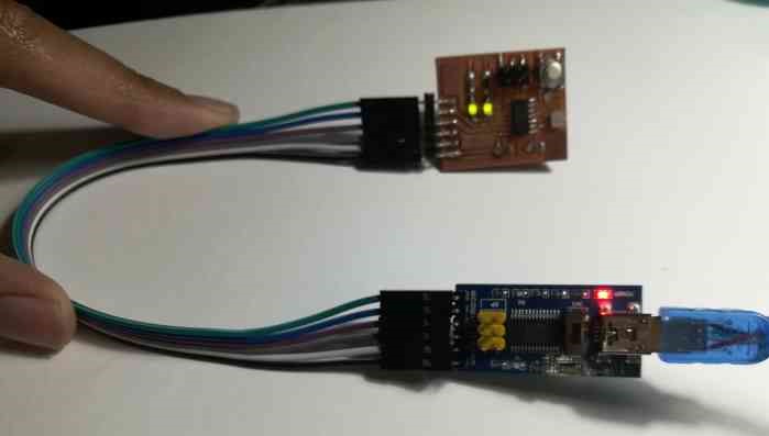
- As shown in the video below, I used the serial monitor to type the famous calling for help message (SOS), clicked send or Enter button, then the monitor displays the message back as it gets translated into light on the board letter by letter or number by number.
Files