12. Output devices - RGB LED
To demonstrate that I’ve designed and programmed a microcontroller board to control an output device, here is video from my Week 16 and Final Project showing a motor being controlled via the serial port and keyboard entry:
More documentation of this video can be found on my Week 16.
This week’s assignments individual assignment: add an output device to a microcontroller board you’ve designed, and program it to do something group assignment: measure the power consumption of an output device
This week I’m aiming for simple…little time (I have been using the supply side time management approach). I’m thinking I’ll make an LED…maybe I’ll try the RGB one that Neil demonstrated.
Components

I started by laying out the components I would need.
Eagle Schematic - downloadable file

I then drew up the schematic and used Nets to connect all the ports. One problem I had was that I used the wrong footprint for the LED. It was originally way too large, so I had to go back into the schematic and make sure I had the right one.
EAGLE Schematic file download here
Data Sheet
ATtiny45 data sheet here I used the data sheet to confirm the ports for the routing the LED.
Eagle Board - downloadable file
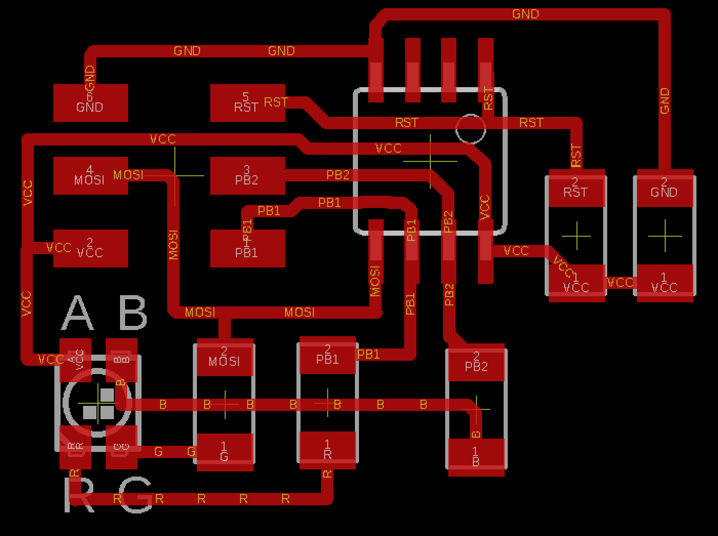
I designed the board to be as minimal as possible, so no voltage regulators or additional headers will be used in my design.
EAGLE Board file download here
MODs Setup

Here’s the typical setup for controlling the Roland mill. I do keep mixing up the ‘Home’ position and the ‘Origin’ position. I’ll get it one of these times. I did 5 offsets to make more space on the board. It does help.
Milled & Soldered Board

Soldering went pretty well. I do like getting everything as square as possible, but that one 1k resistor wouldn’t stay put!
Programming
I used Neil’s C code: http://academy.cba.mit.edu/classes/output_devices/RGB/hello.RGB.45.c
I’m not totally sure what’s going on in the code, but I think as I continue to build up the workflow across machines and softwares I’ll develop intuitions about the details, even if they’re a little fuzzy still. It works for me.
And I also used Neils’ Makefile: http://academy.cba.mit.edu/classes/output_devices/RGB/hello.RGB.45.make
Video Result
Success!:
The LED worked on the first try - that’s a first. It’s getting a little easier each time! If necessity is the mother of invention, repetition is the father of learning. Turns out ‘lil Wayne said that first:
Another Output Example
To demonstrate that I’ve designed and programmed a microcontroller board to control an output device, here is video from my Week 16 and Final Project showing a motor being controlled via the serial port and keyboard entry:
More documentation of this video can be found on my Week 16.