Week sixteen: Interface and Application Programming
For this week, we had to write an application that interfaces with an input or output device that we made. I chose to design a board using the atmega 328 microcontroller and an output board with LEDs and communicate them with a mobile application using the bluetooth module HC-05
Board
Thinking in my final project, i decided to design and fabricate a electronic board using ATmega 328p as microcontroller,
because it is compatible with the arduino libraries, in addition to having better capacity and a greater number of input and output pins than the Attiny 44 or 45.
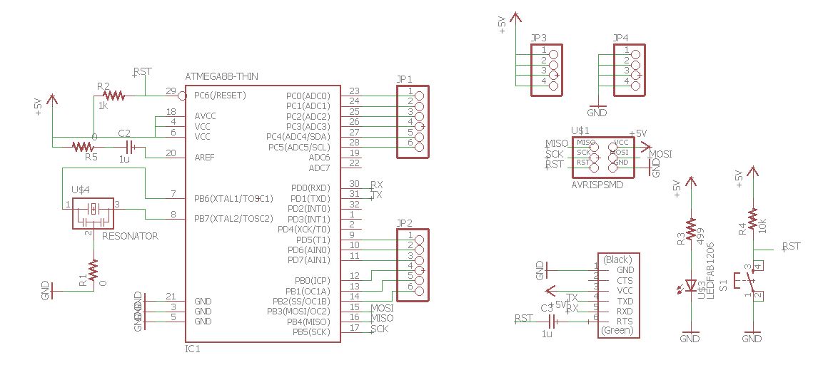
The design was based on the famous Satsha kit, I used a 20 MHz oscillator and a reset button. Also place 6 digital and 6 analog pins, 4 VCC pins, 4 GND pins, a pin header to burn bootloader with ISP i made in week 5. And the connection pins for the FTDI, which includes Rx and Tx.
As you can see in the schematic design
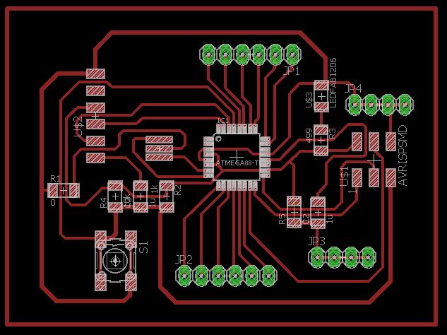
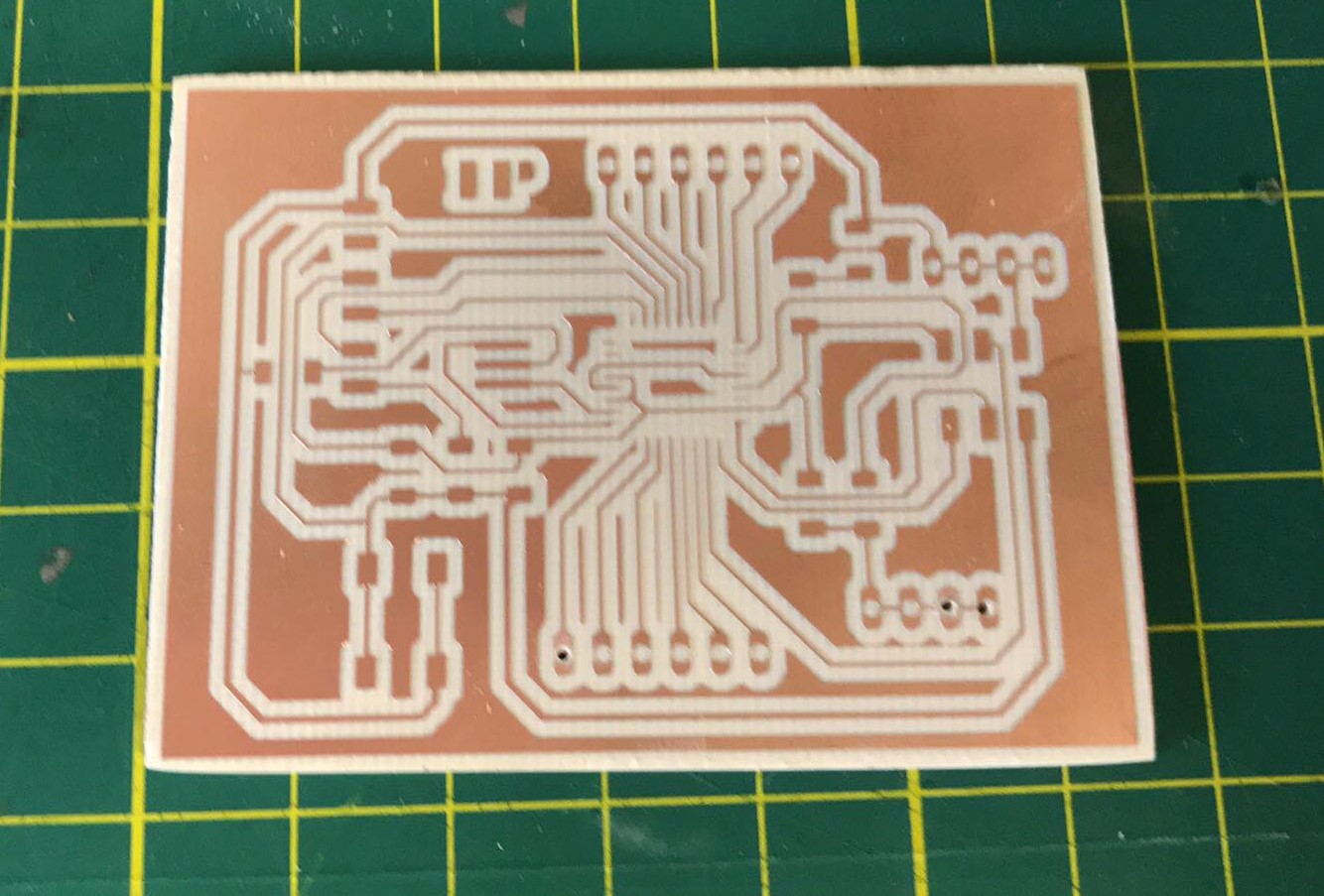
After several attempts I managed to finish the design of the electronic board using two 0 ohms resistors as bridges to be able to skip some traces. Also, I could pass 2 traces under the resistances, because in fab modules i selected diammeter of 1 mm. This allowed me to have a lot of precision.
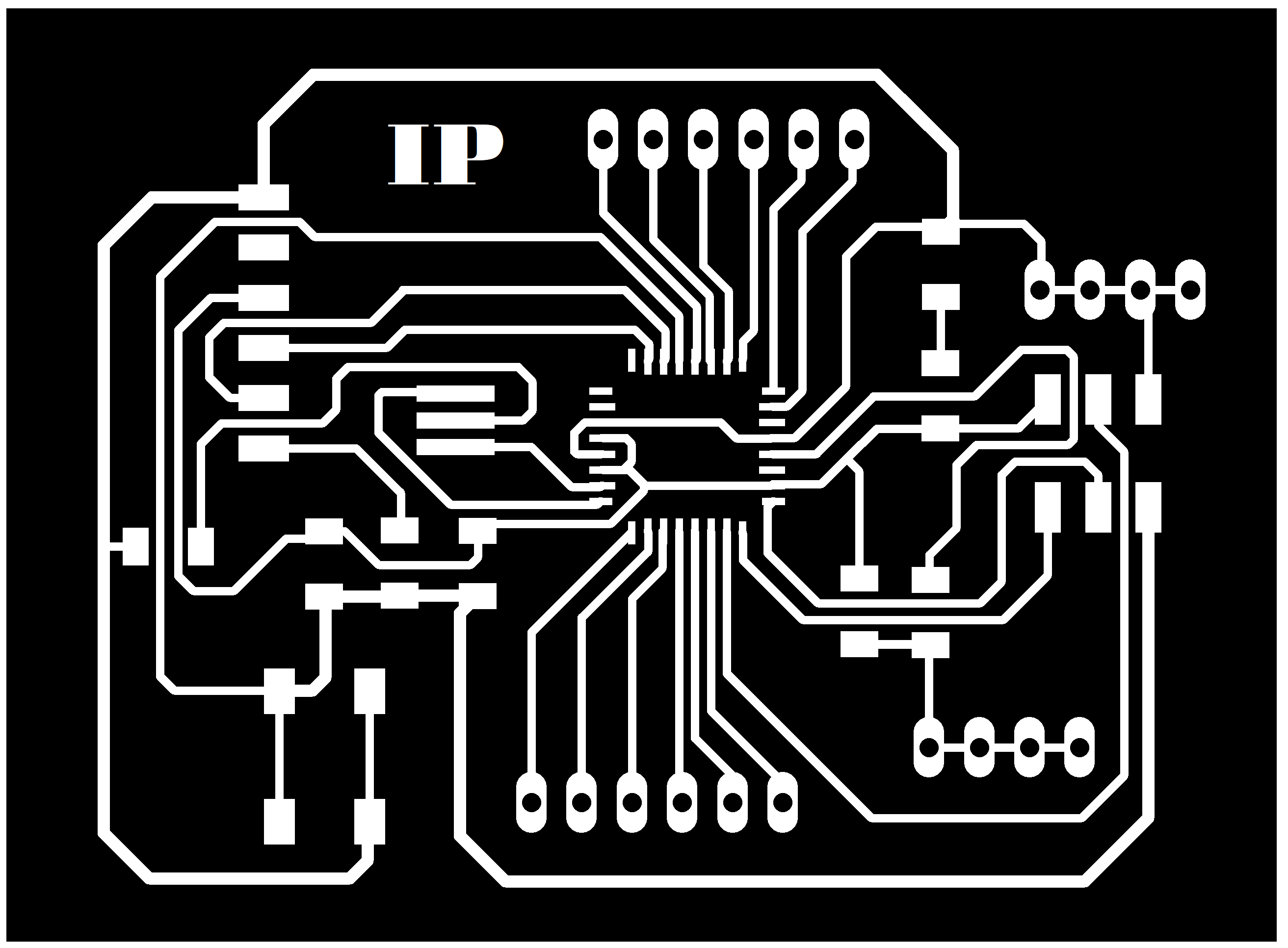
I exported the image of my board in the png extension and cut it and put the initials of my name in paint. Then I used fab modules to perform the CAM with the usual parameters
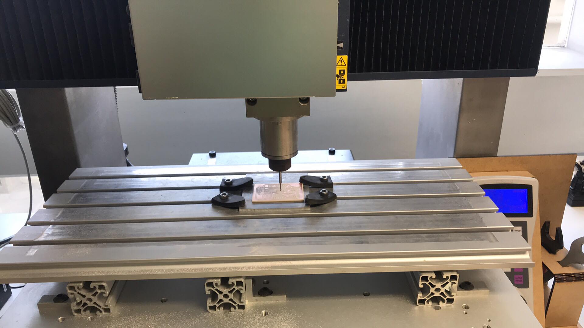
As usually i fabricated my board in Roland MDX-540
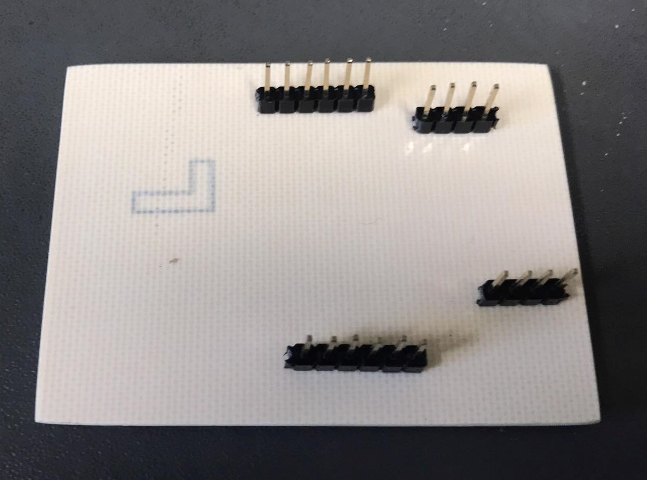
Making holes
First i soldered the true hole
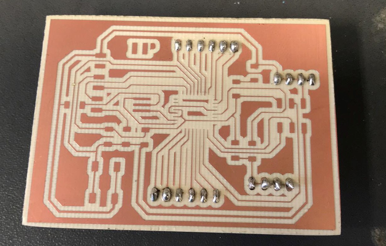
I took a long time to weld the atmega328, since the copper traces were very thin, but this is the result!
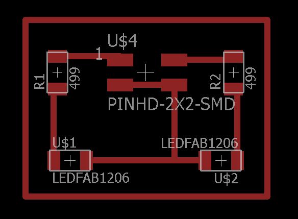
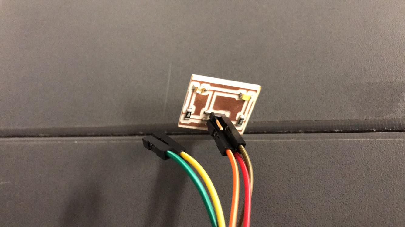
I also designed an output board that contains 2 leds, 2 resistances of 499 ohms and a pinheader 2x2 where it will connect with the digital output and GND pins of the atmega 328
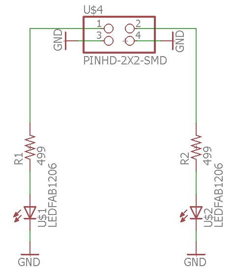
Output board
Communication
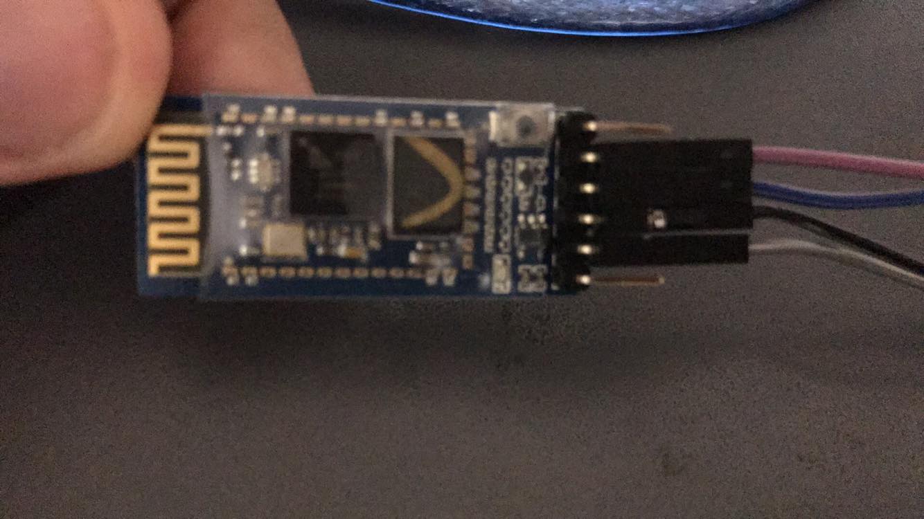
For this assignment I decided to use wireless serial communication using a bluetooh module HC-05, since I want to create an interface for cell phone
App inventor
App Inventor is a software development environment created by Google Labs for the development of applications for the Android operating system. It is free and the programming is simple, it is based on interlacing blocks with specific functions, such as conditional, actions and communication.
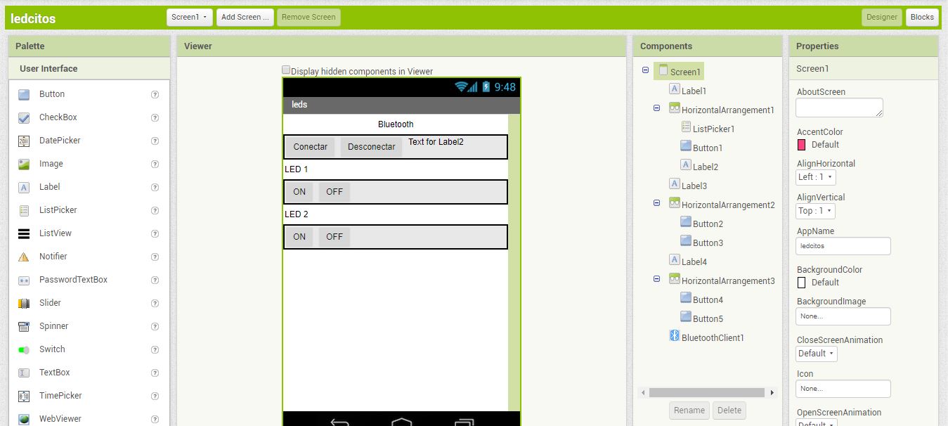
The procedure to create the interface is relatively simple, select the buttons that I wanted to use and the list picker command, I also placed a label that will depend on the connection status, this programming will be done later by blocks. I added the bluetooth function here in non-visible components
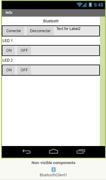
Here you can see the screen that will be visible on the mobile android
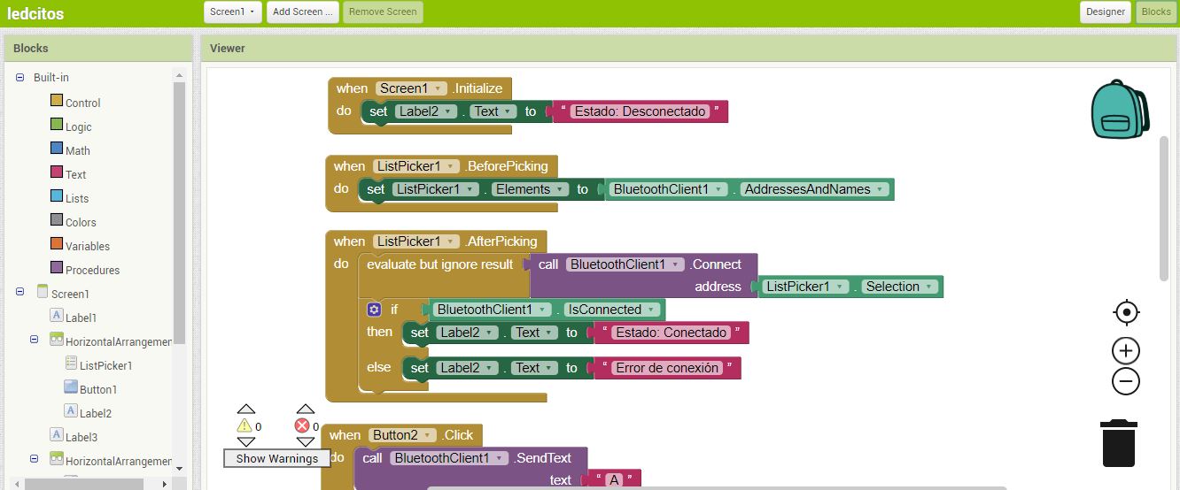
Here the functions of the interface are programmed, when the screen initializes the label it will say "disconnected", this referring to the bluetooth communication, likewise the lists of devices that are available will be shown, once selected depending on the connection the label will say "connected "or" disconnected ", I created 4 buttons then I will create a condition for each button, for example when button 1 is pressed, the text" A "will be sent via bluetooth, which we will use as input for programming in arduino. Finally I think the function disconnect to end the communication
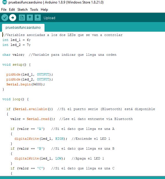
As I mentioned earlier, when you press the buttons of the mobile application, text variables will be sent, so in arduino I created the following conditional, if the bluetooh serial communication is available and a text value "A" is received, then the led will light up, If a "B" value was received, the led will turn off
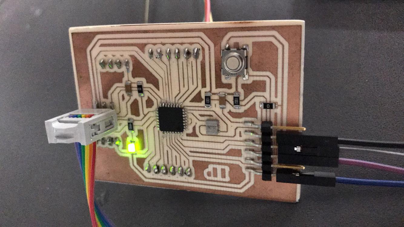
Once the appinventor project has been exported as an apk, I open it with my mobile phone through the port of my laptop, as the arduino program is already uploaded, I make all the necessary connections, my ISP programmer will energize atmega 328, which is connected to the bluetooth module by the Tx and Rx pins, finally the pairing between the cell phone and the bluetooth module is done. Here a demonstration.
Downloads
Atmega 328 Schematic
Atmega 328 Board
Leds output board schematic
Leds output board
App inventor project .aia
App inventor project.apk
Arduino program
To see the complete development of the group assignment visit the following link that corresponds to the CIT page