Week fourteen: Networking and communications
Individual assignment
This week, we have to design, build, and connect wired or wireless node(s) with network or bus addresses
Serial bus communication
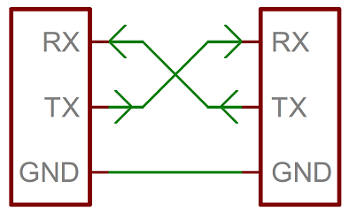
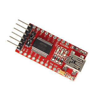
This week I chose to make the example of serial bus communication, using several hello world boards, in my case I will use the FTDI to communicate the laptop (master) to the nodes (slaves) through a bridge
Fabrication of the boards
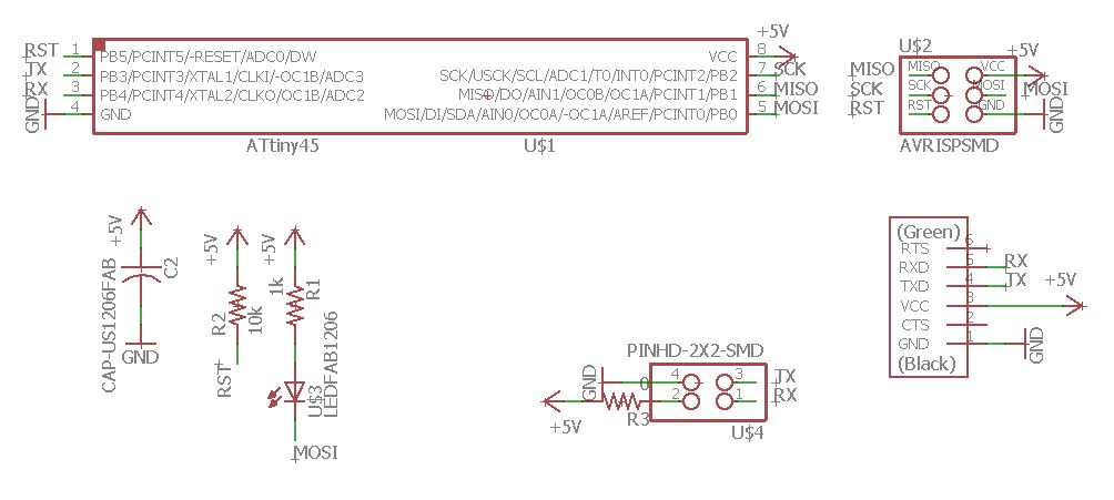
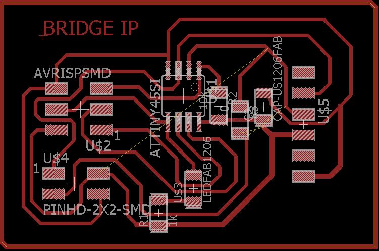
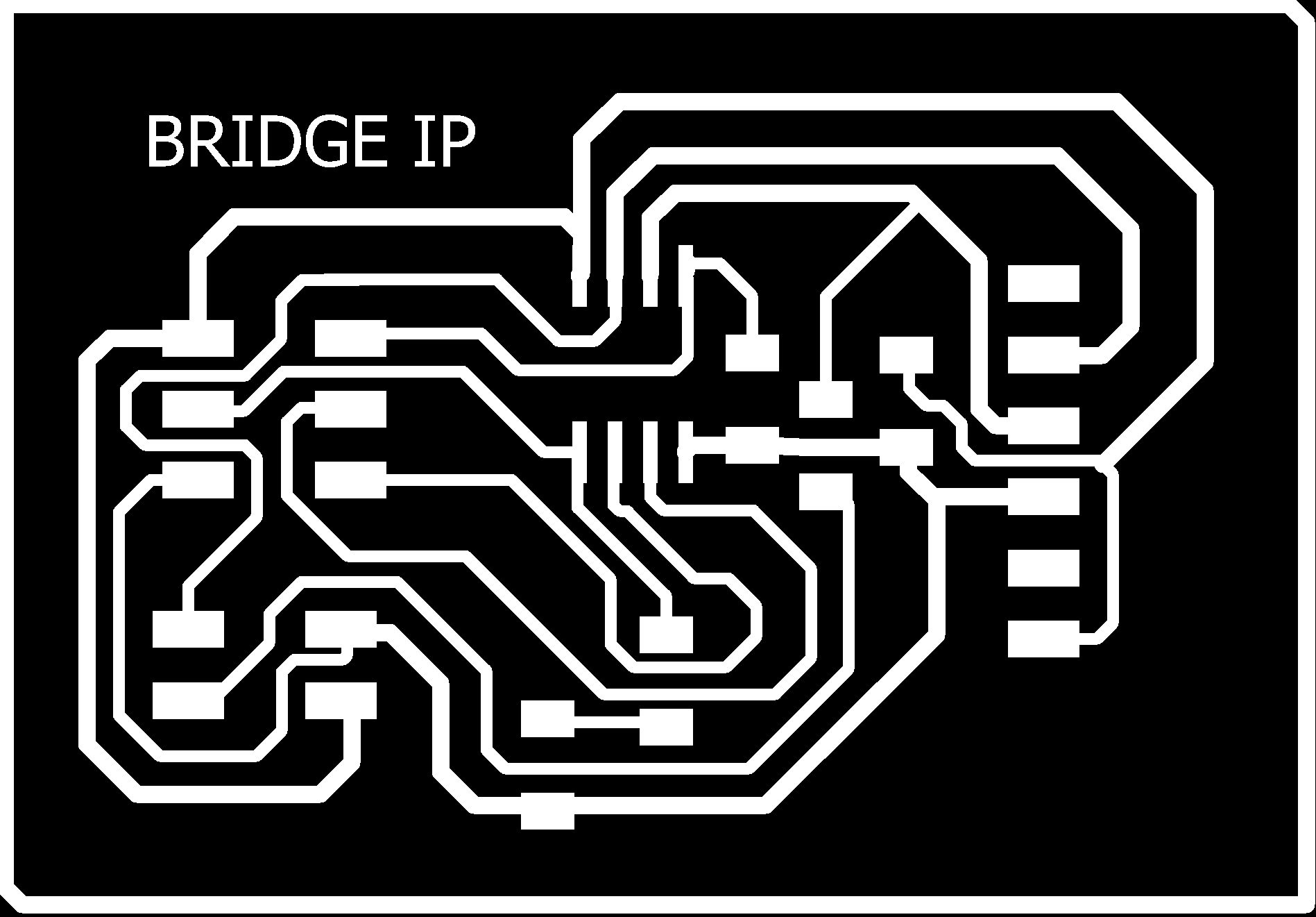
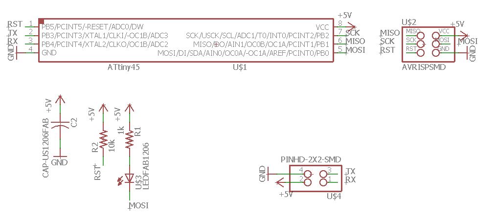
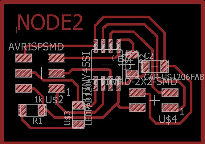
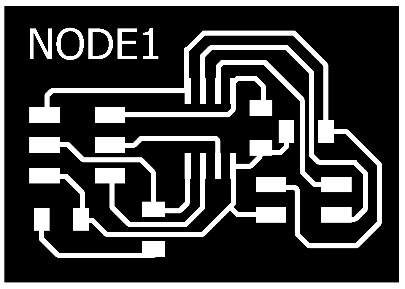
Based on the Neil plates, I designed my version using the Eagle software, both the bridge and the nodes have an LED connected to the MOSI pin, and a 2x2 pinheader for the serial bus communication with the PB3(Tx) and PB4(Rx) pins of the ATtiny 45. Each board has a 3x2 pinheader to burn bootloader.
I used a 0 ohm resistor as bridge to skip the traces
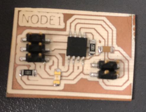
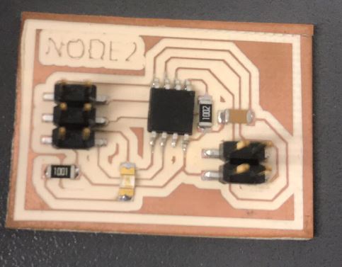
After the soldering this is the result
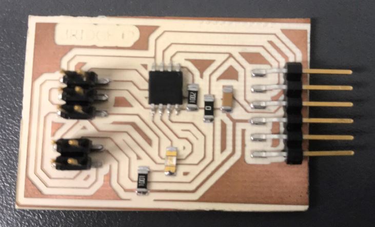
Node 1 is the same as node 2, i just changed the number
Result
Code
First, I had to burn bootloader to each of the boards using my ISP programmer
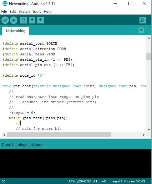
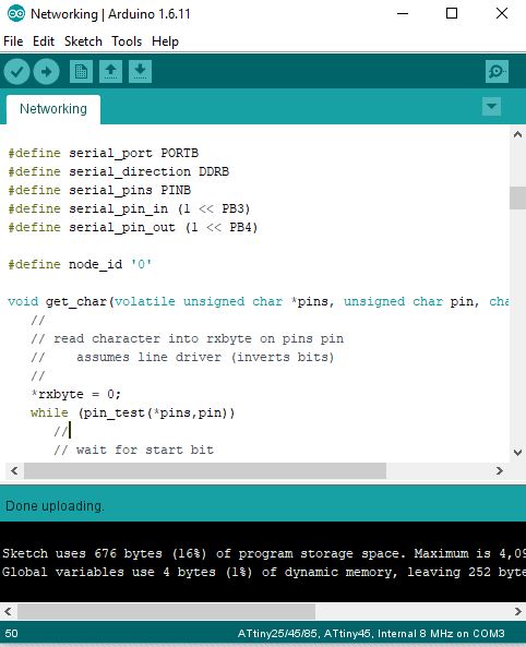
Then, using the Neil code in C language for serial bus communication, I uploaded each of the electronic boards
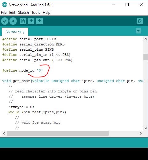
I made two nodes and one brigde. I modified the “c” code; for example on the brigde de id number was “0” (# define node_id “0”) and the nodes “1” (# define node_id “1”) and “2” (# define node_id “2”).
Testing
We connect the bridge to the pc and this to the nodes using the 2x2 pinheader
.jpg)
And we tried the communication by typing "node #" with the number that we want to activater
.jpg)
UPDATE
At the beginning, understanding Neil's code may seem complicated, but the trick is to first understand the #define that he uses, because he repeats them when he programs in C. I would say that these are the most important functions to understand the logic :
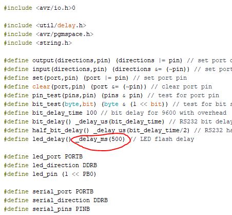
#define output(directions,pin) (directions |= pin) // set port direction for output
#define input(directions,pin) (directions &= (~pin)) // set port direction for input
#define set(port,pin) (port |= pin) // set port pin
#define clear(port,pin) (port &= (~pin)) // clear port pin
#define node_id '0'
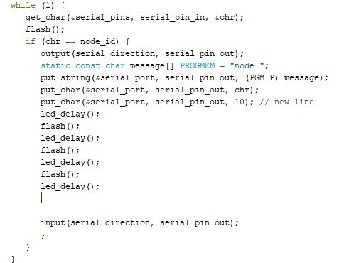
Initially the Tx pin is as an input, due to the input function, previously declared, when the "id" is detected as a character (0,1,2,3), corresponding to each board, the set function will be used. to convert the PORTB of the serial communication to 0, and the pin associated with Tx will become an OUTPUT pin using the function declared above, and will execute the action corresponding to the programming, the action is in the flash void and can vary in time (delay) and number of times the LED turns on or off. When finished executing the action it will be an INPUT pin again thanks to the function, in addition, the same "stop bit" sending function makes it return to 0, this is important because if we wanted to program it using another language like Arduino, this does not it would be included and we would have to program it to return to 0 so that the communication works correctly several times.
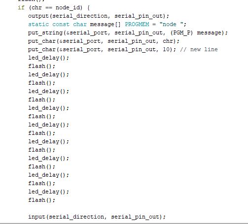
Modify some lines of code to vary the actions of each board when its id is called.
When the bridge is called by its id "0", it will turn on 3 times in 500 ms intervals
 When node1 is called by its id "1", it will turn on 7 times in 50 ms intervals

Next a demonstration video
Group assignment
My personal contribution was to manufacture my node 2 as output for the communication of all the projects and to manufacture the cables with pinheaders that will be used for the serial communication to the Tx and Rx pins of each individual board
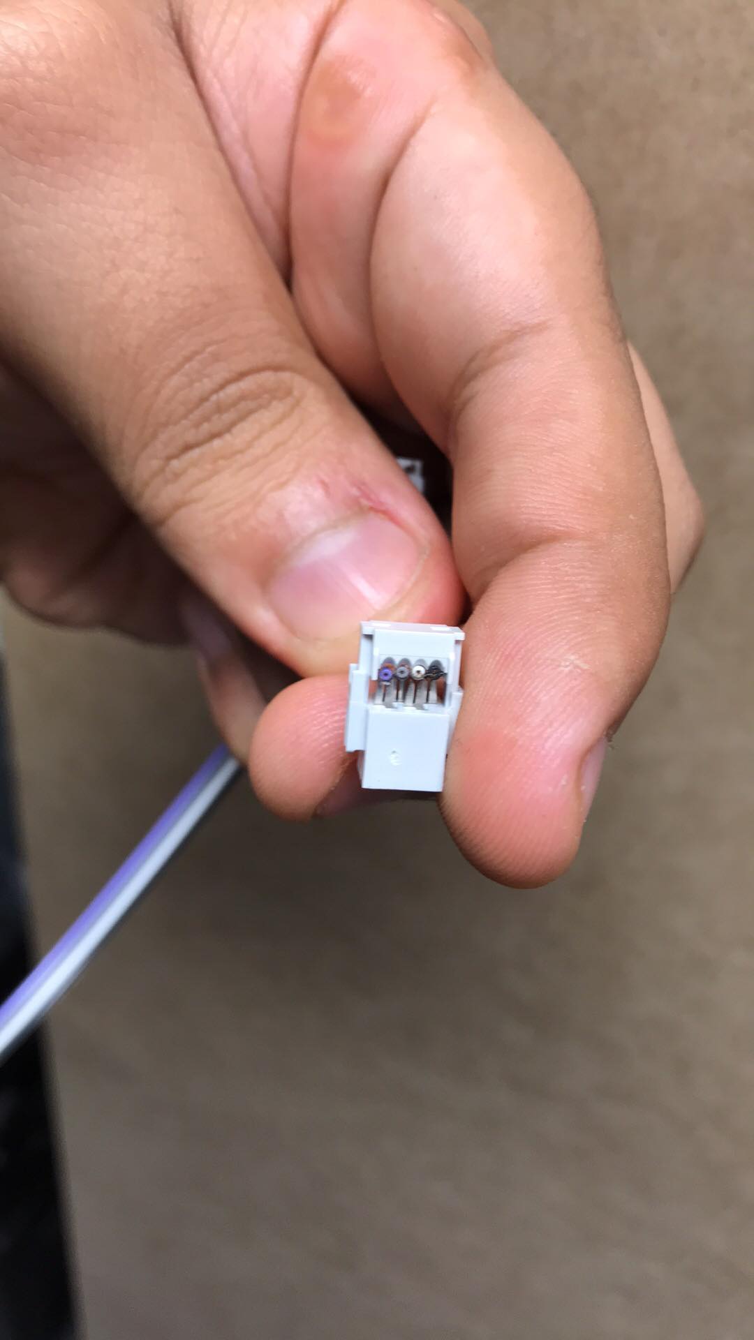
To assemble the communication cables I used 4 jumpers or dupont cables and 2x2 pinheaders, since they will communicate VCC, GND, Tx and Rx
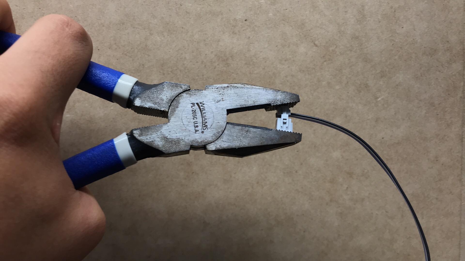
with the help of a pliers of ression, I nail the blades on the cables
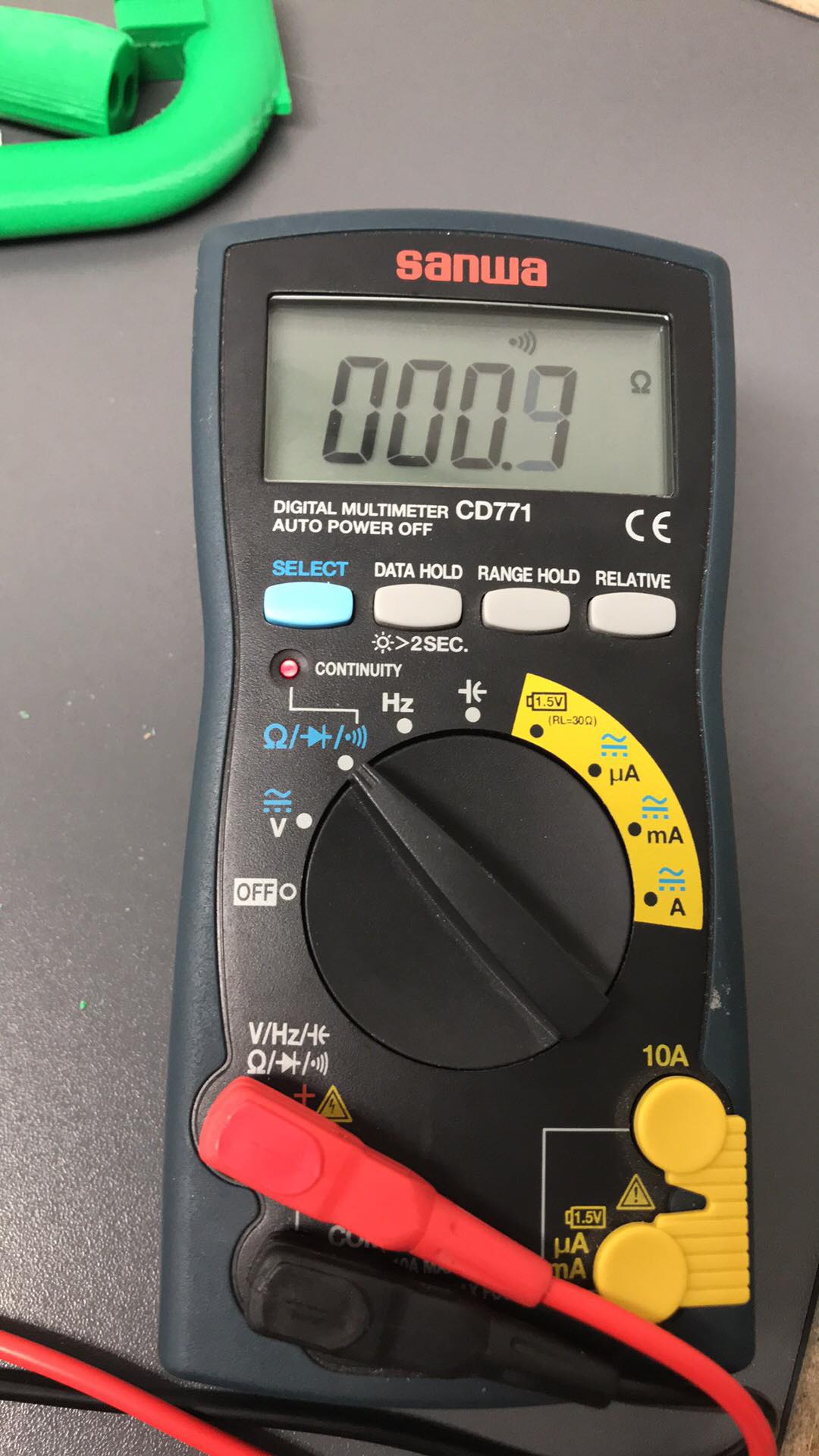
Then I test continuity at both ends on all the pins
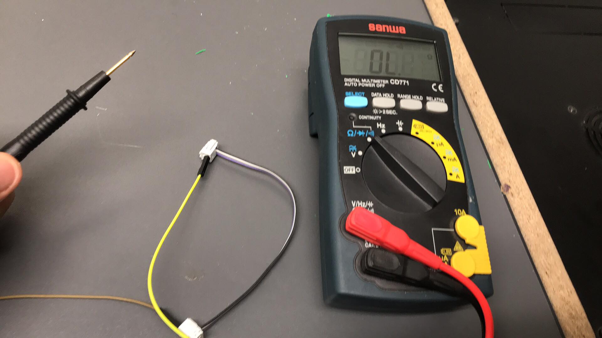
Quality control passed, ready to use to communicate our projects!
Downloads
Bridge schematic
Bridge board
Bridge png
Node schematic Node board
Neil's C code
Updated code bridge
Updated code node1
To see the complete development of the group assignment visit the following link that corresponds to the CIT page