experimentation
make it happen
Group Assignment - participants:Josep Marti, Felipe Santos, Alberto Lopez, Diar Amin, Gustavo Abreu
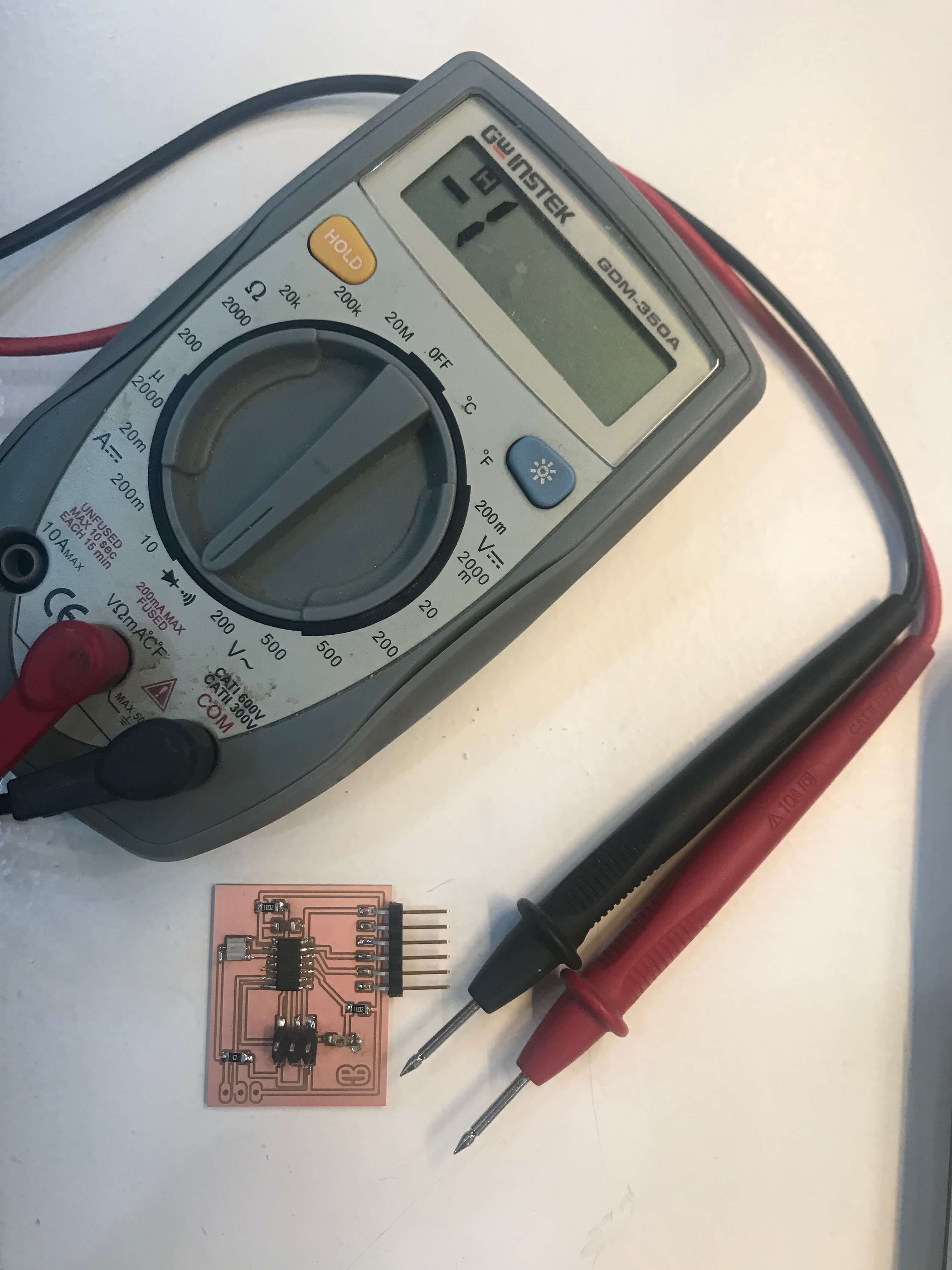
In this weekly assignment we had to measure the power consumption of an input device. Unfortunatly the Oscilloscope in the FabLab was broken this week, so we skipped this task for now and checked what it is about online. This video is helpful to understand how it works. Basically - to measure the analog and digital signals of a device with a multimeter you have turn the knob to the V~/- position and use the correct positive connection of the multimeter, plug the probes in parallel with the analog or digital pins of your device and turn it on.
Individual assignment:
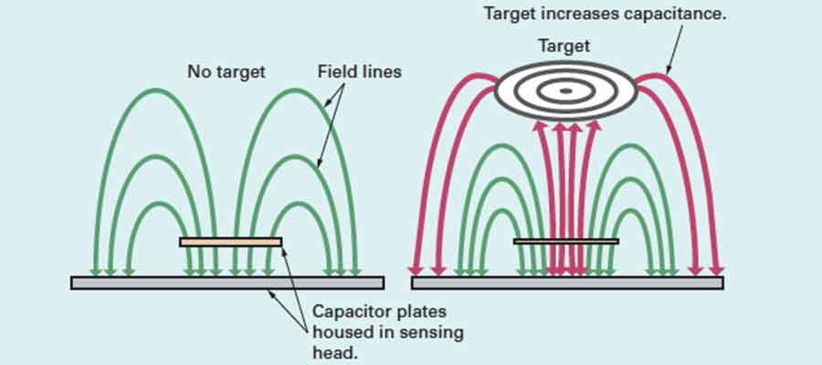
aim of exploration: Hall sensor, LDR Sensor, Capacitance
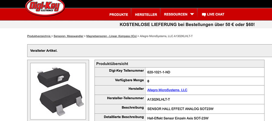
Check the hall sensor component on digi-key.
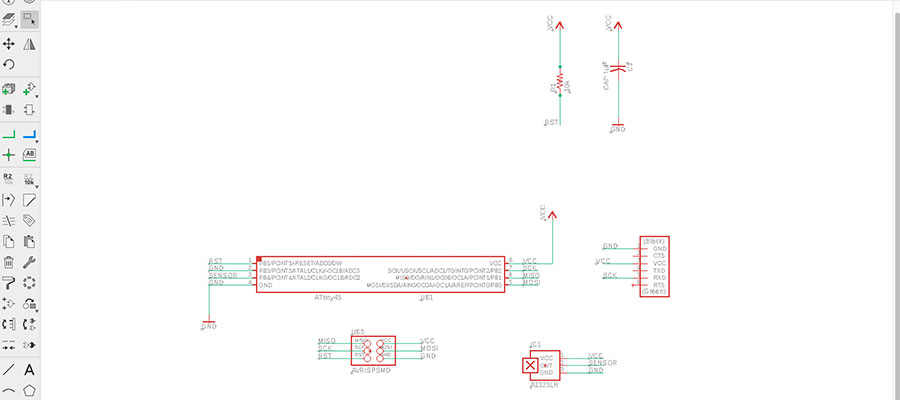
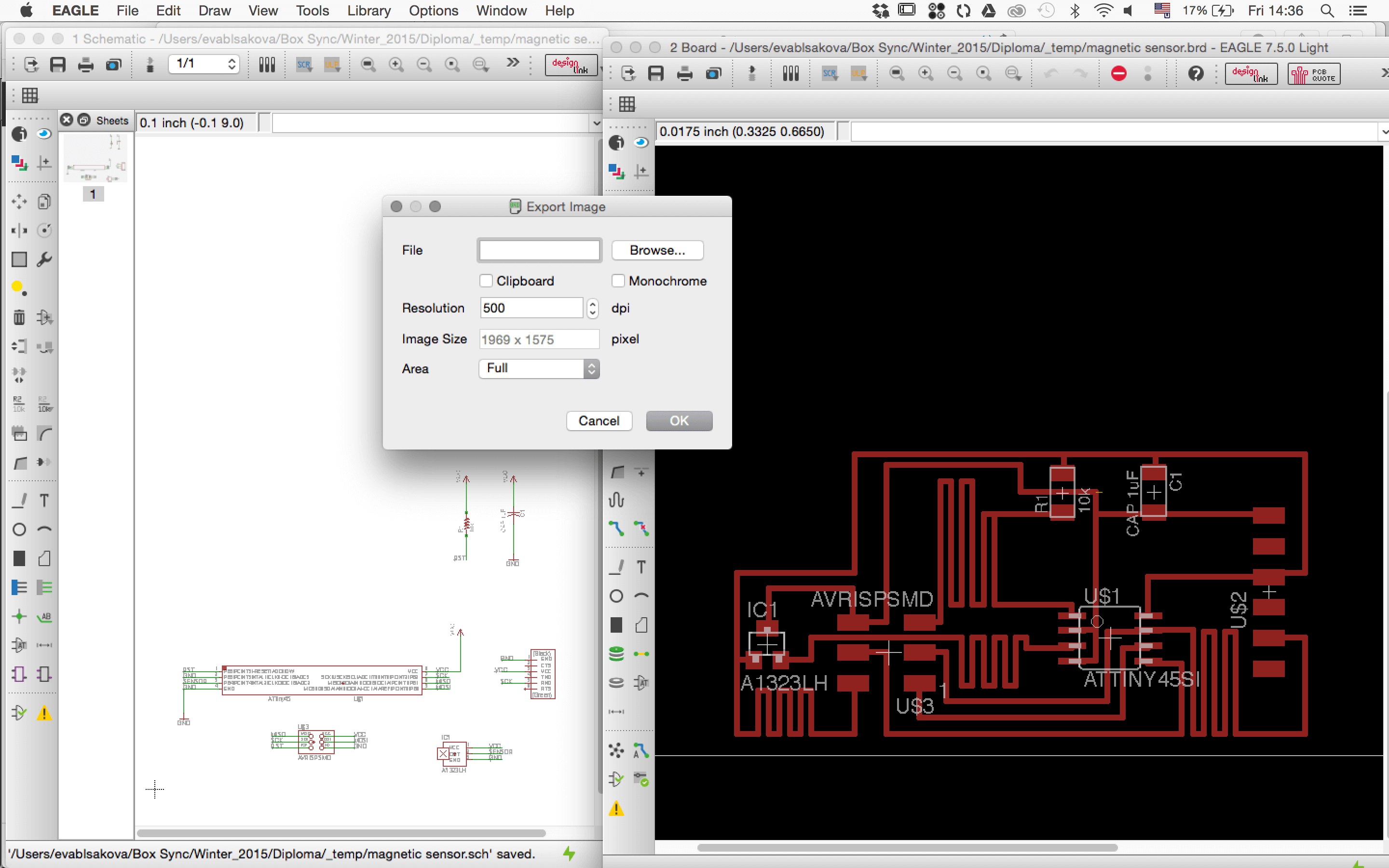
I decided to make the Hall effect Sensor Board. Started with the creation of schematics in Eagle.
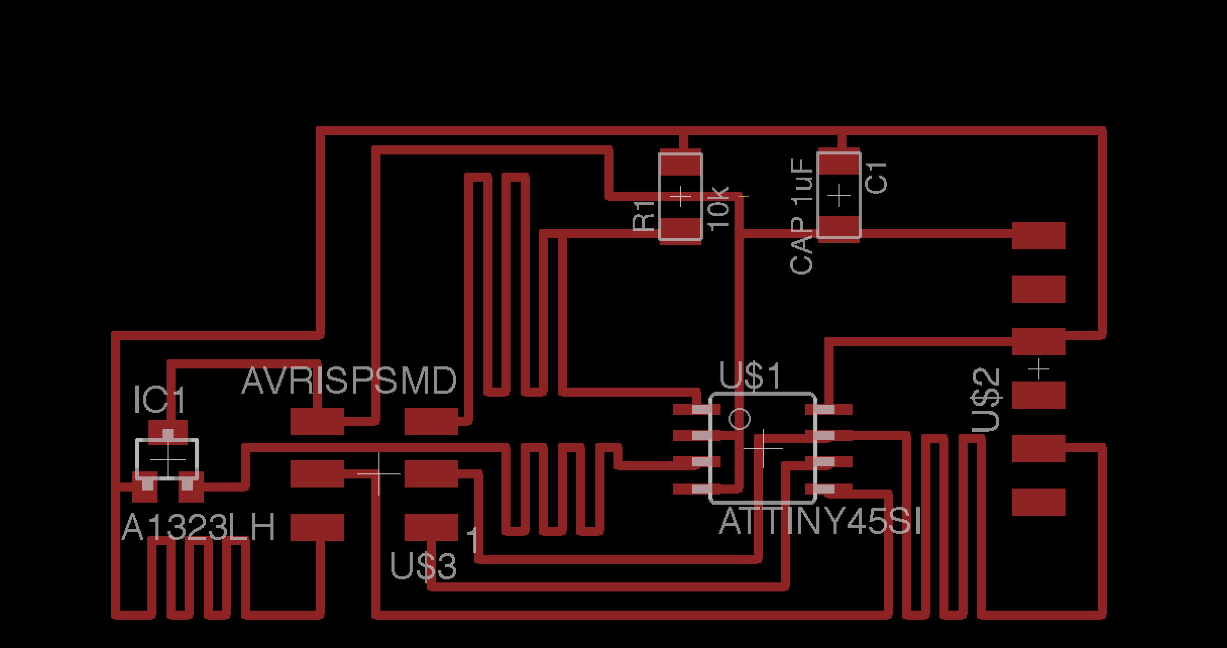
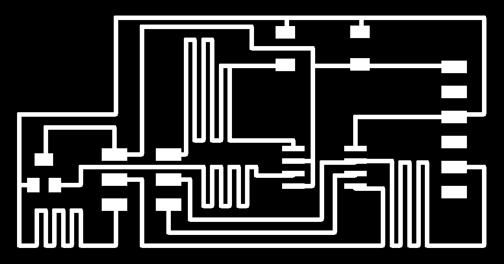
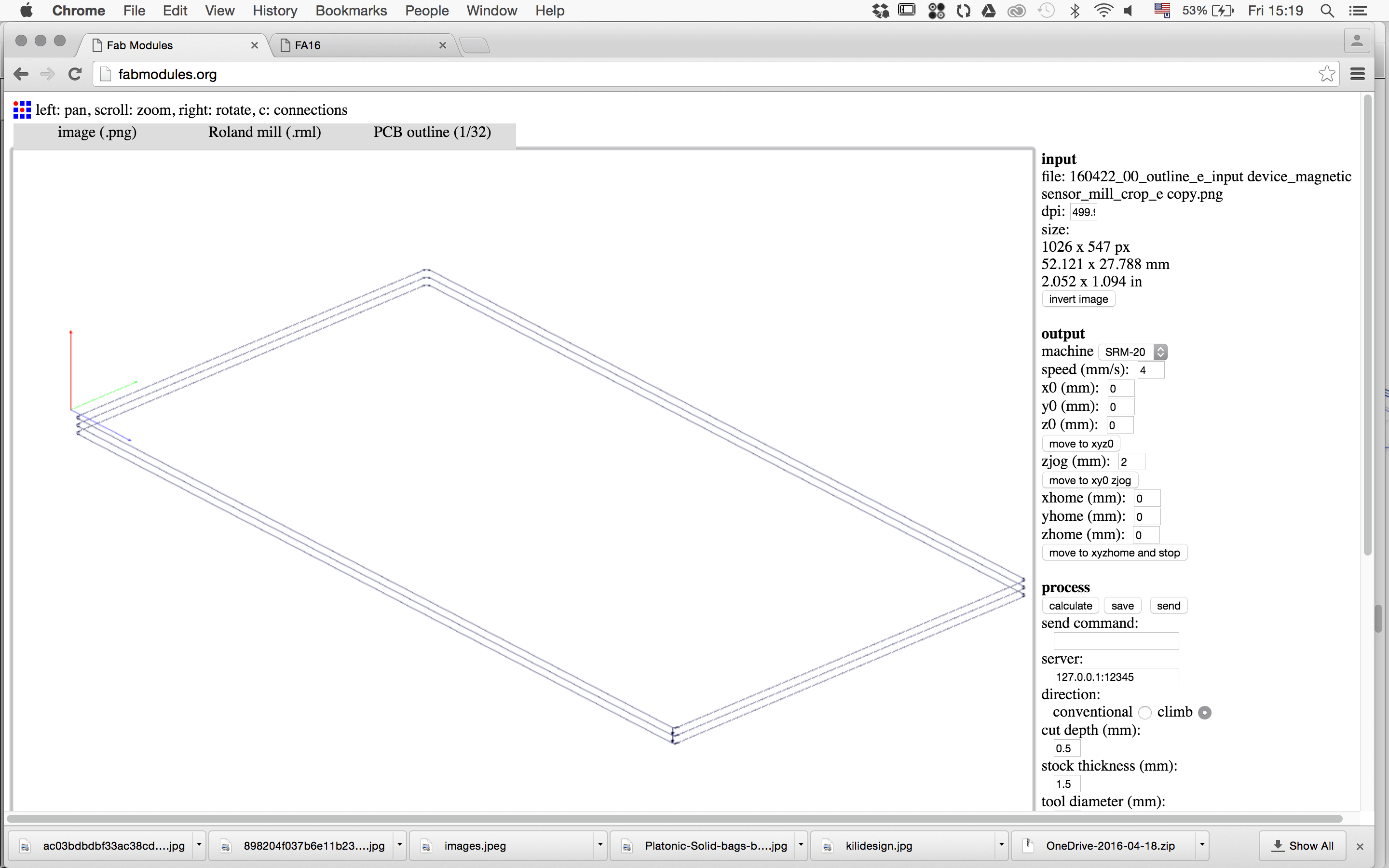
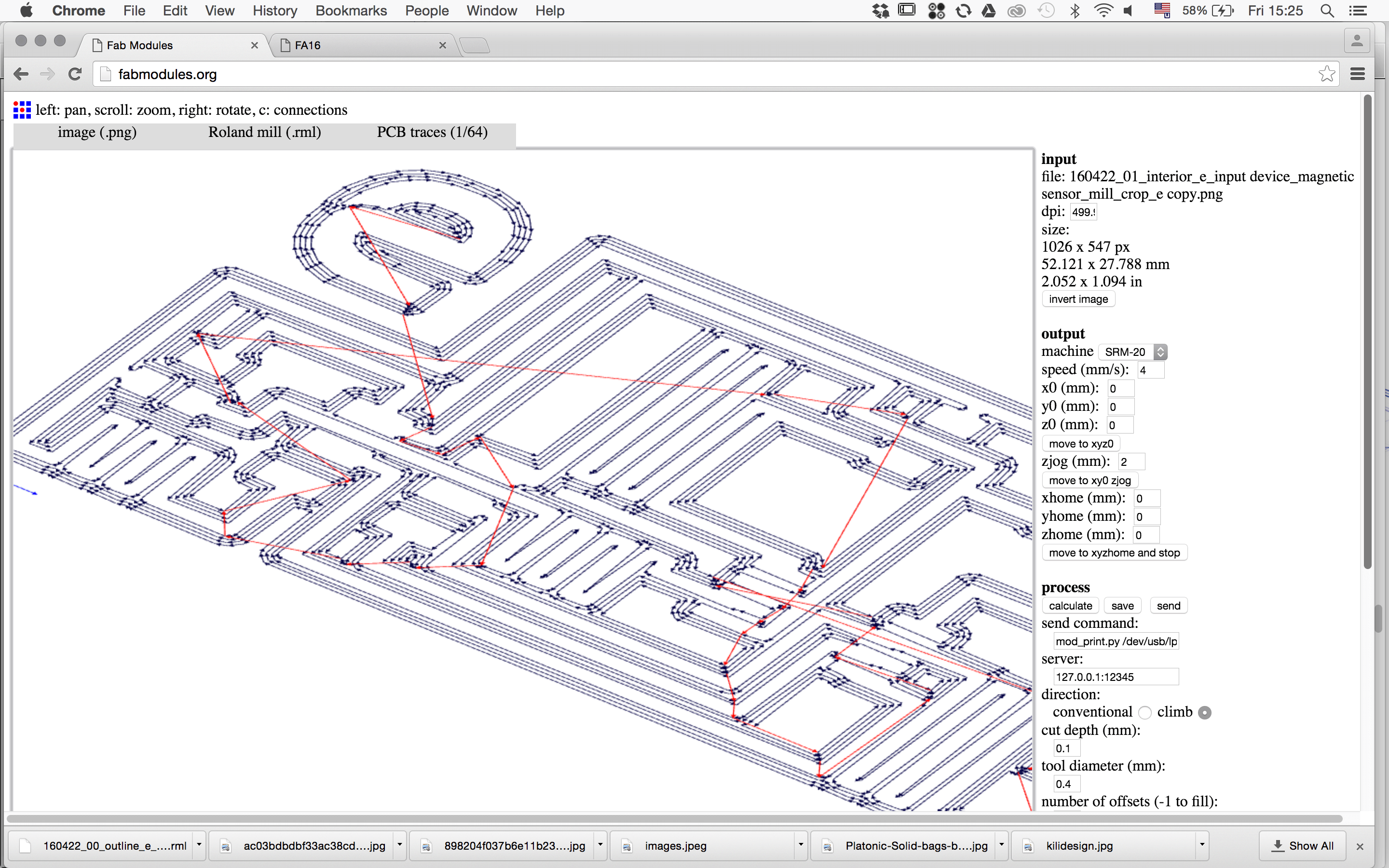
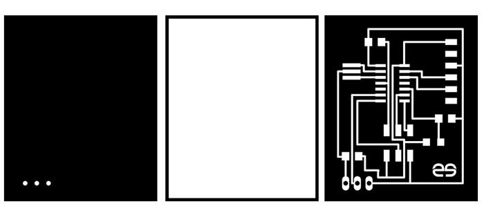
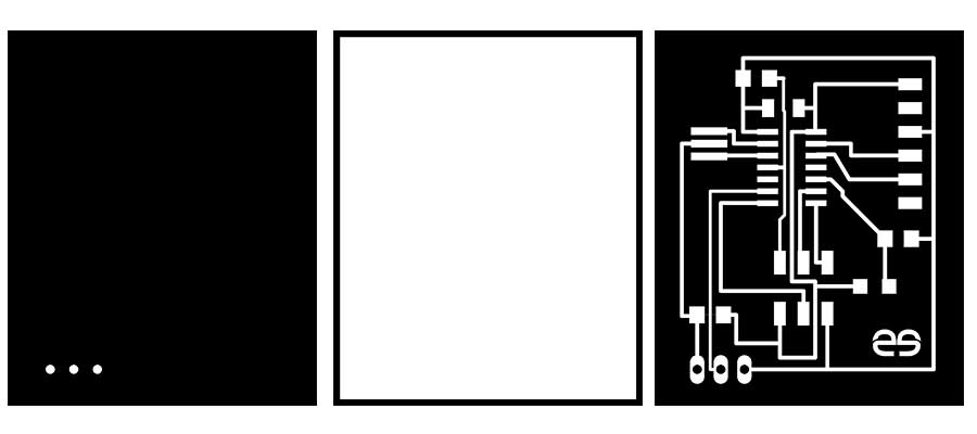
Designing the traces. I went bit crazy with graphicall appearence of the traces...just for a testing this SW...exported traces+outline...the same procedure as explained in electronix week.
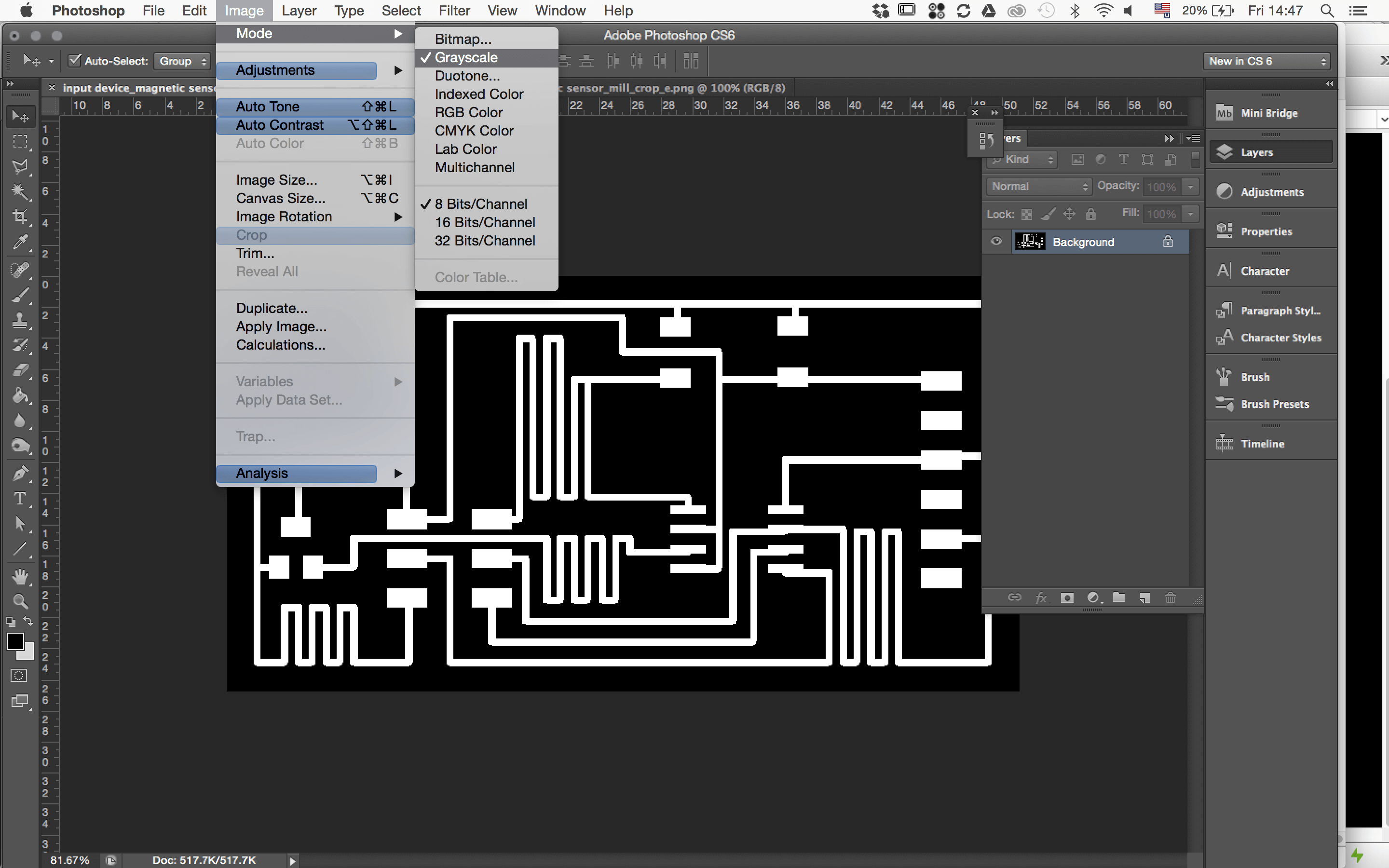
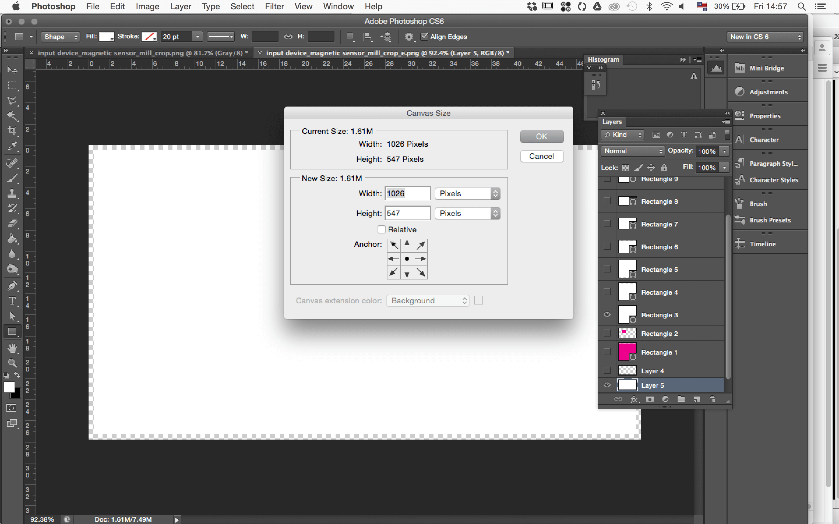
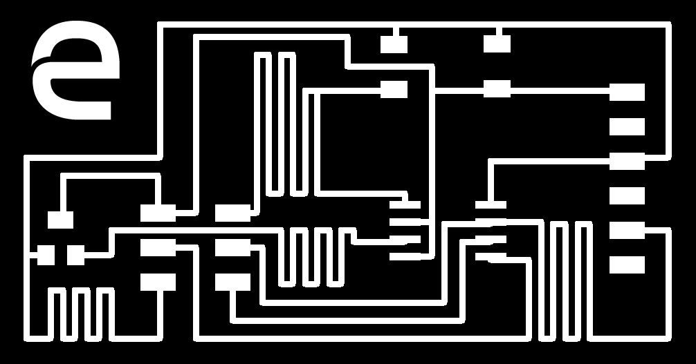
took it to photoshop to lable it.
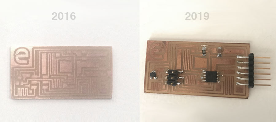
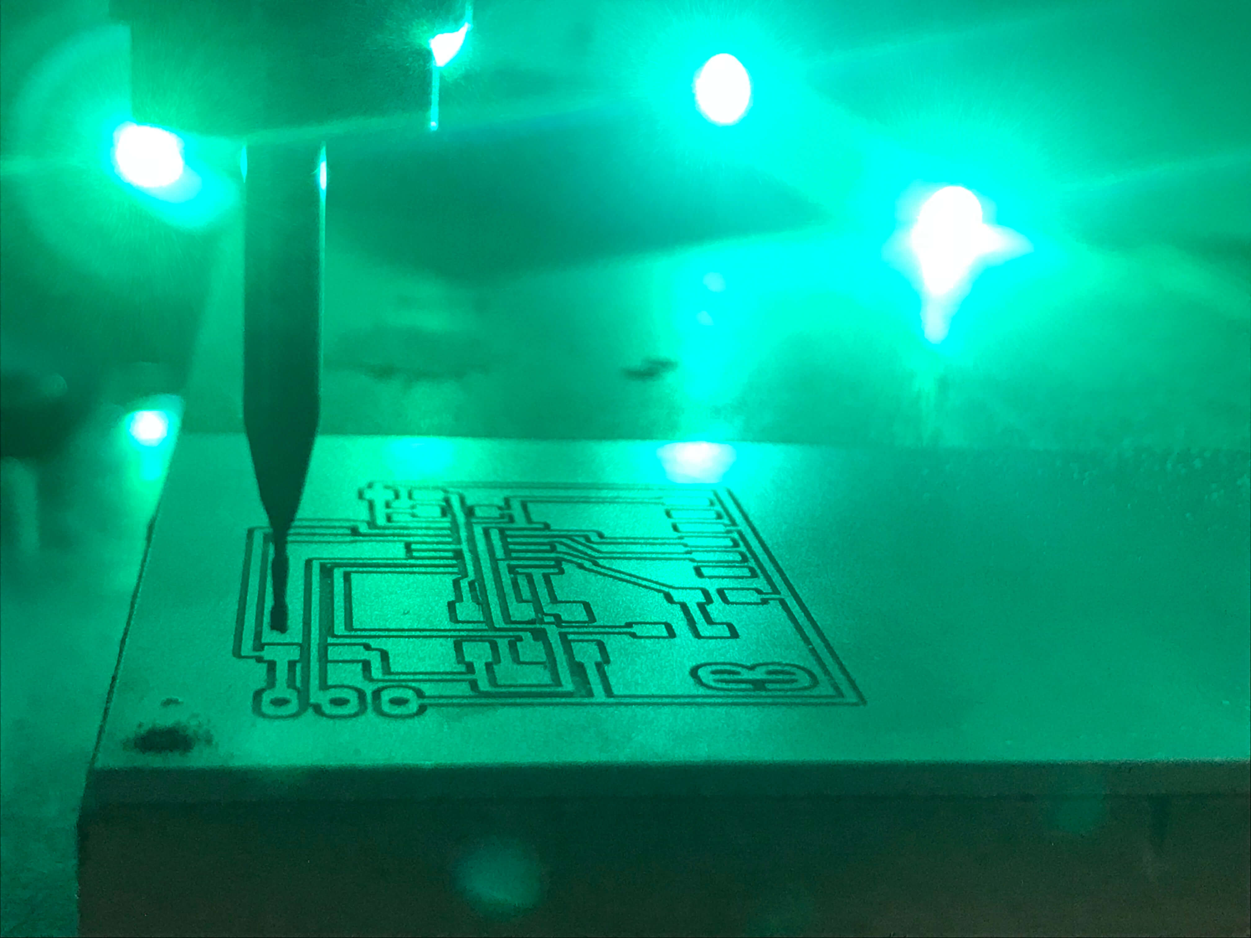
Freshly milled board captured in 2016 vs board with components captured in 2019.
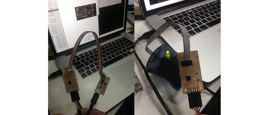
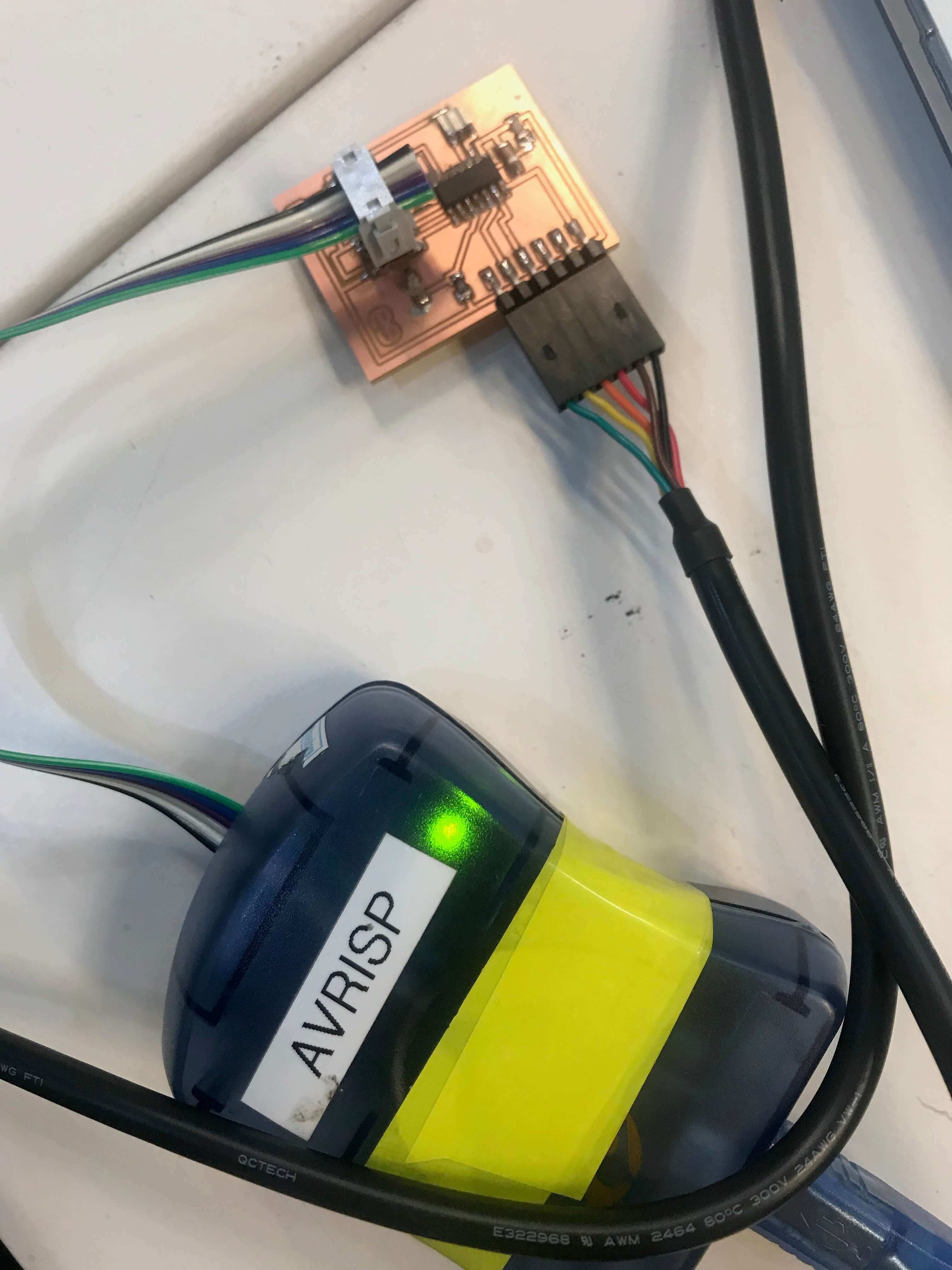
#programmingsetup - connect ISP programmer (the one what I created back in 2016 was not working anymore unfortunately, sad story)
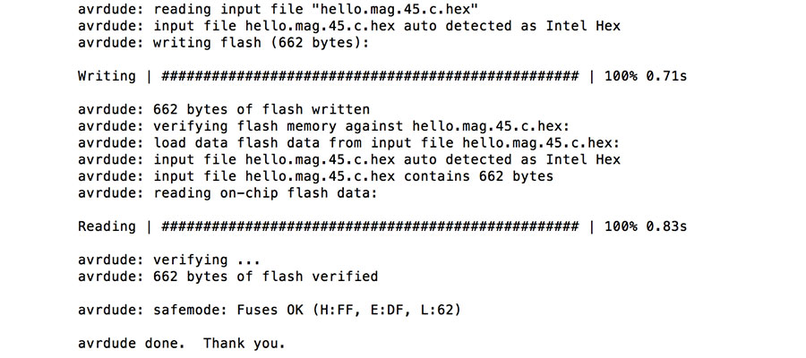
#programming
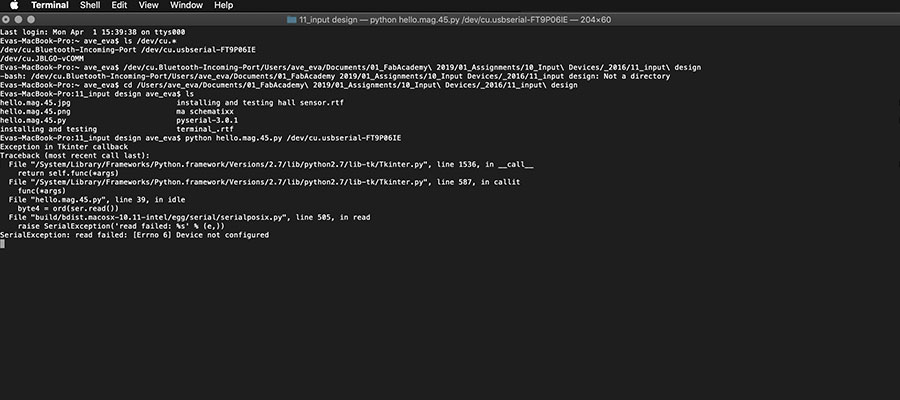
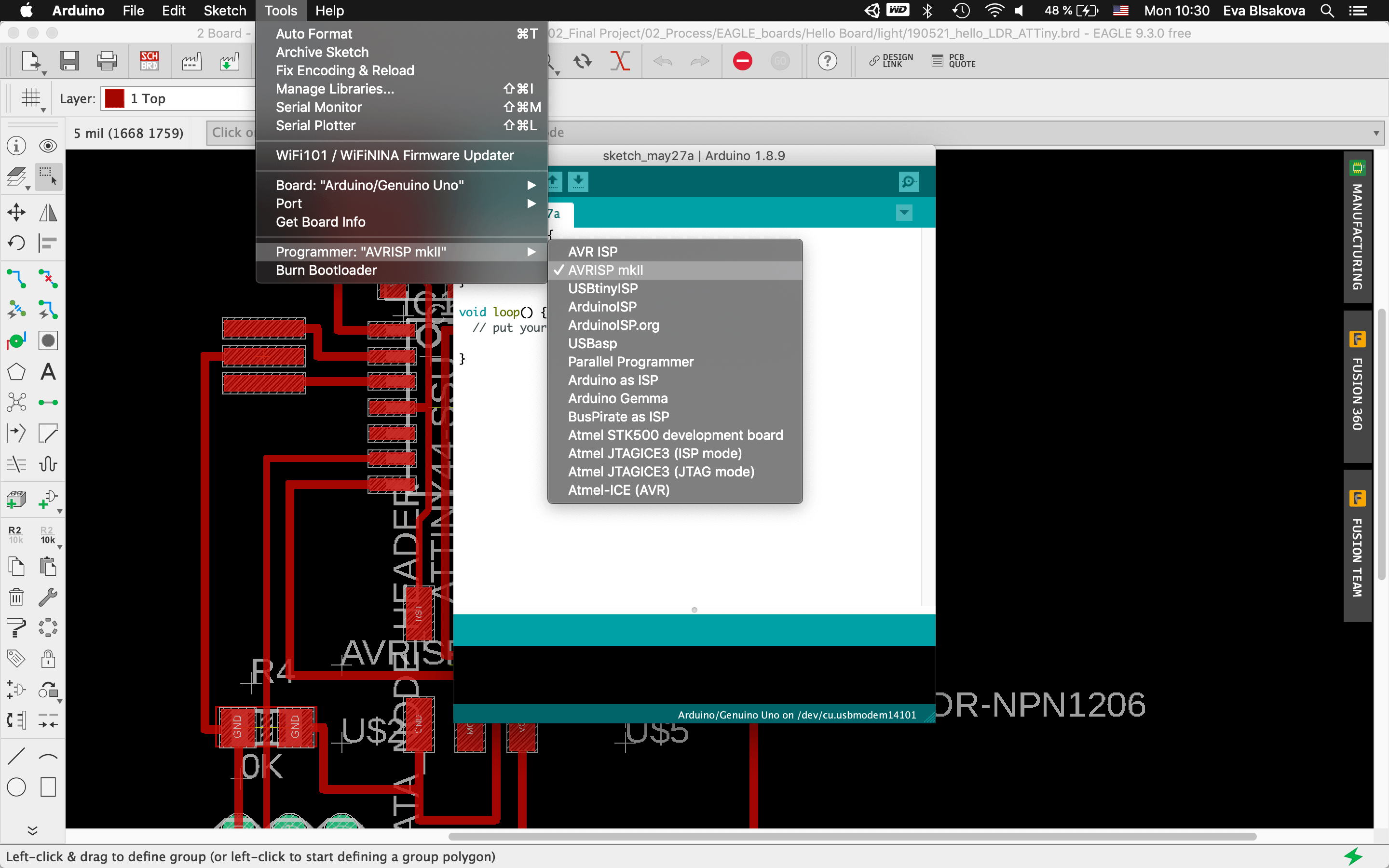
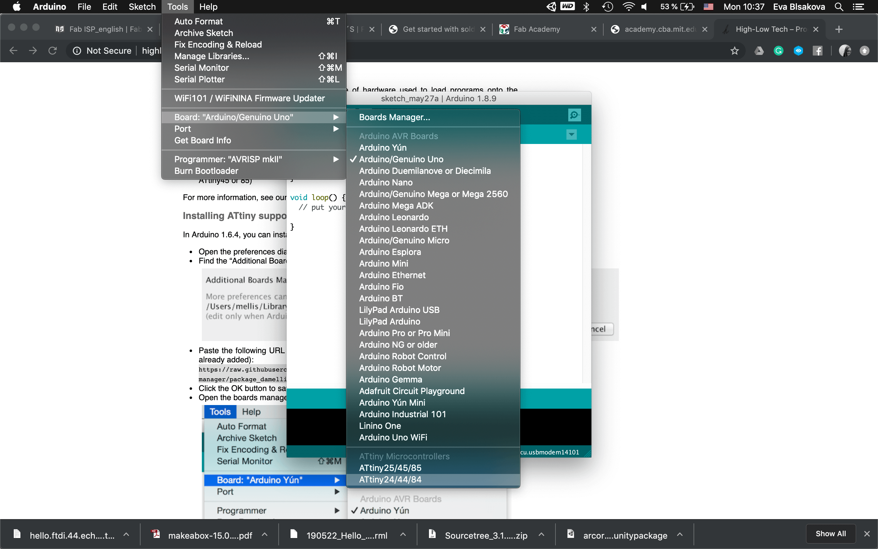
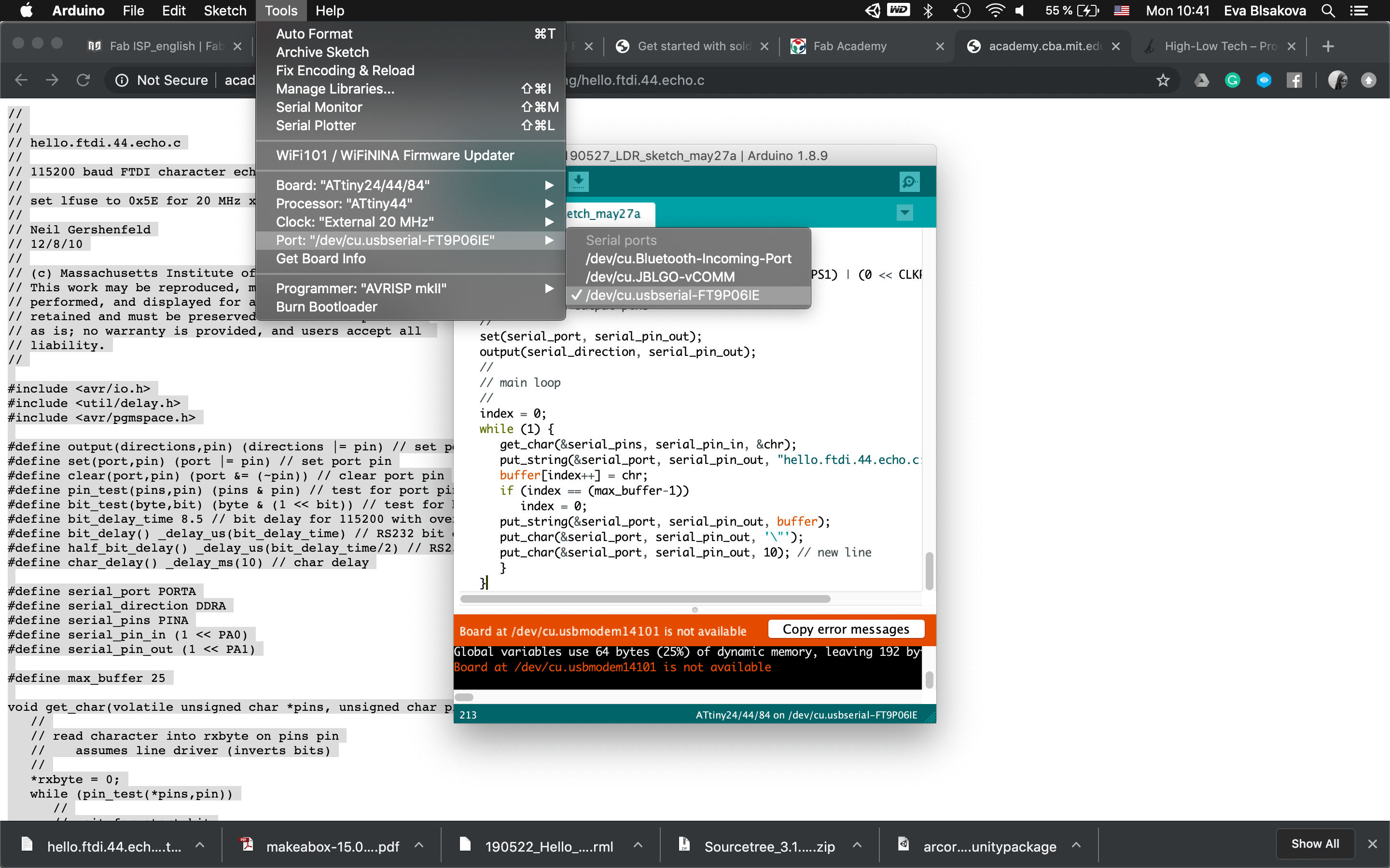
#steps needed to do before: installing python, pyserial-3.0.1, new components for xcode To check the PORT, in the terminal, we can use following commands: ls /dev/cu.* /dev/cu.Bluetooth-Incoming-Port or Arduino>Tools>Port>...than you will see ports available...as on pic...
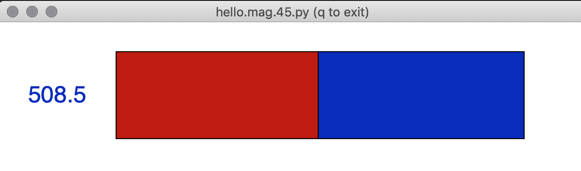
#demonstration #appinterface #hallsensorinteractionidentification
Video of hall sensor in action. For demonstration I didnt have stronger magnet by hand so I used the one embeded in my laptop where you connect charger.
download files
Next step, after discussing my final project with my instructors in FabLab, I decided to make something more alighned with the direction of my final project. Therefore I chose to make an another board including another input device - capacitive sensor /step response. I will implement it within one board to be able to control LED stripe when touched. For that I decided to switch to KiCad and followed the tutorial what we did in previous clases. But after I decided to go back to Eagle, I was more comfortable since I had previous skills already. Anyway, exploring KiCad SW and its possibilities was a very good excercise.
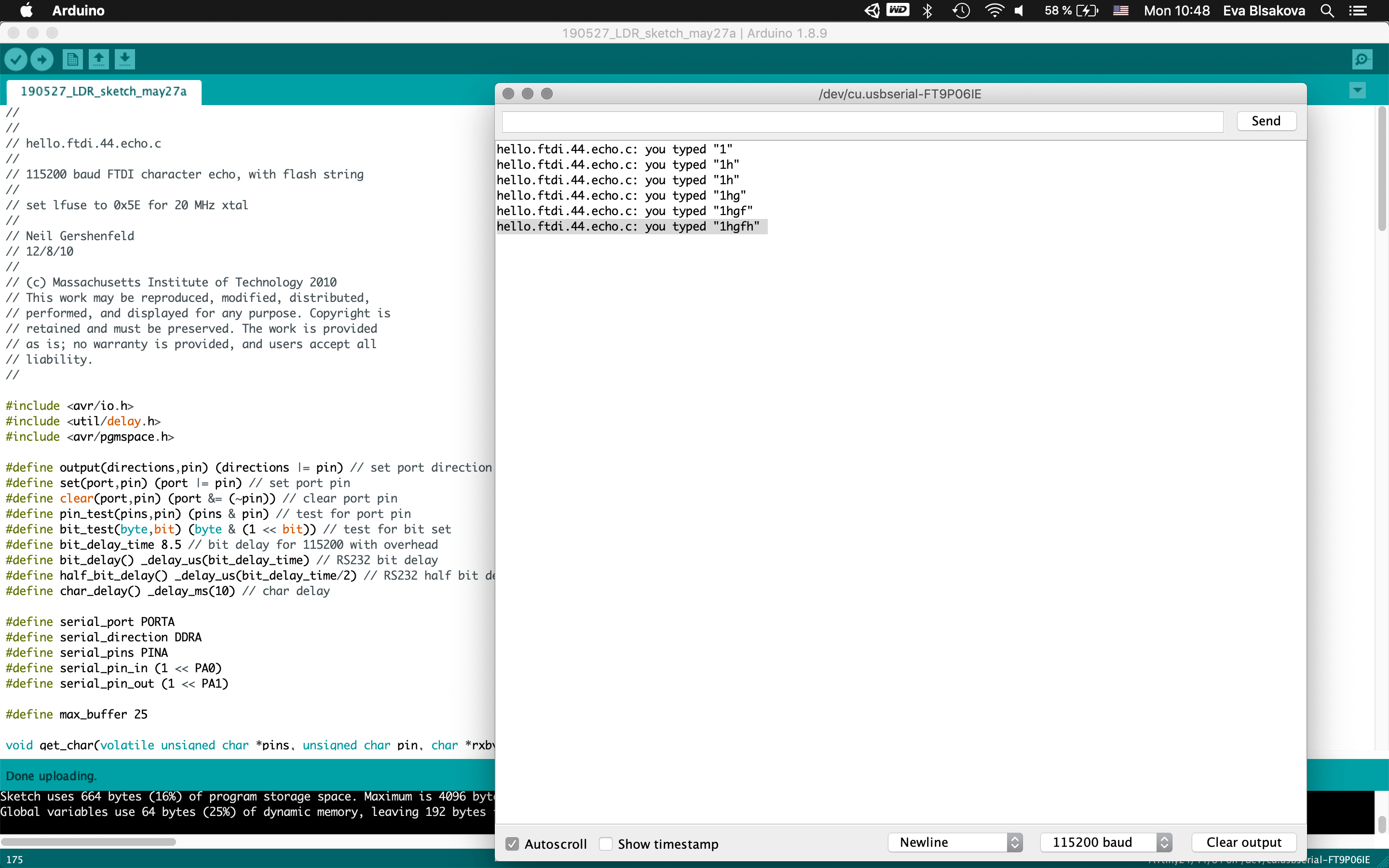
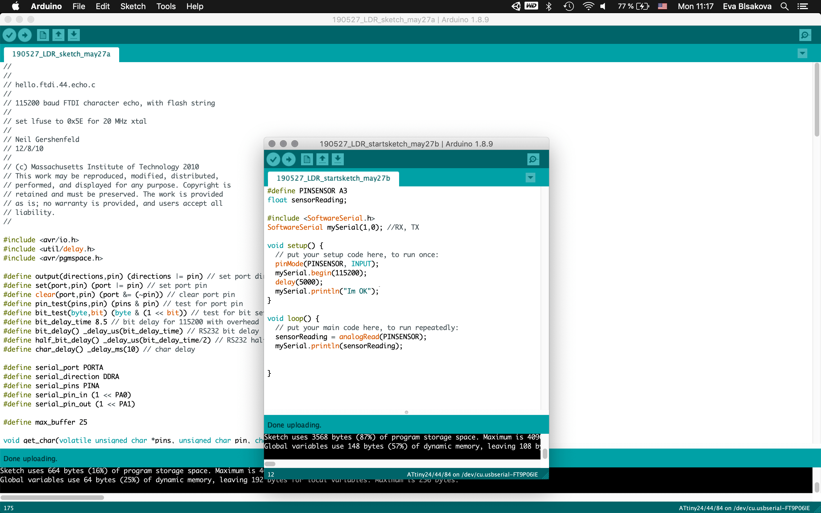
#testing - I had played around with some arduino components (LED, LDR, Potentiometer) following this tutorial.
And than I had an idea to implement LDR sensor within my final project concept as a reaction to ambient light.
LDR sensor
Question - What is an LDR (Light Dependent Resistor)and how it works?
LDR sensor - photoresistor (or light-dependent resistor) is a light-controlled variable resistor. An LDR is a component that has a (variable) resistance that changes with the light intensity that falls upon it. This allows them to be used in light sensing circuits.The resistance of a photoresistor decreases with increasing incident light intensity; in other words, it exhibits photoconductivity. ...needs more explanation to include from my notes.
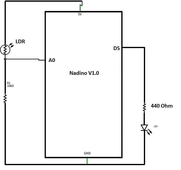
LDR circuit explained in this diagram.
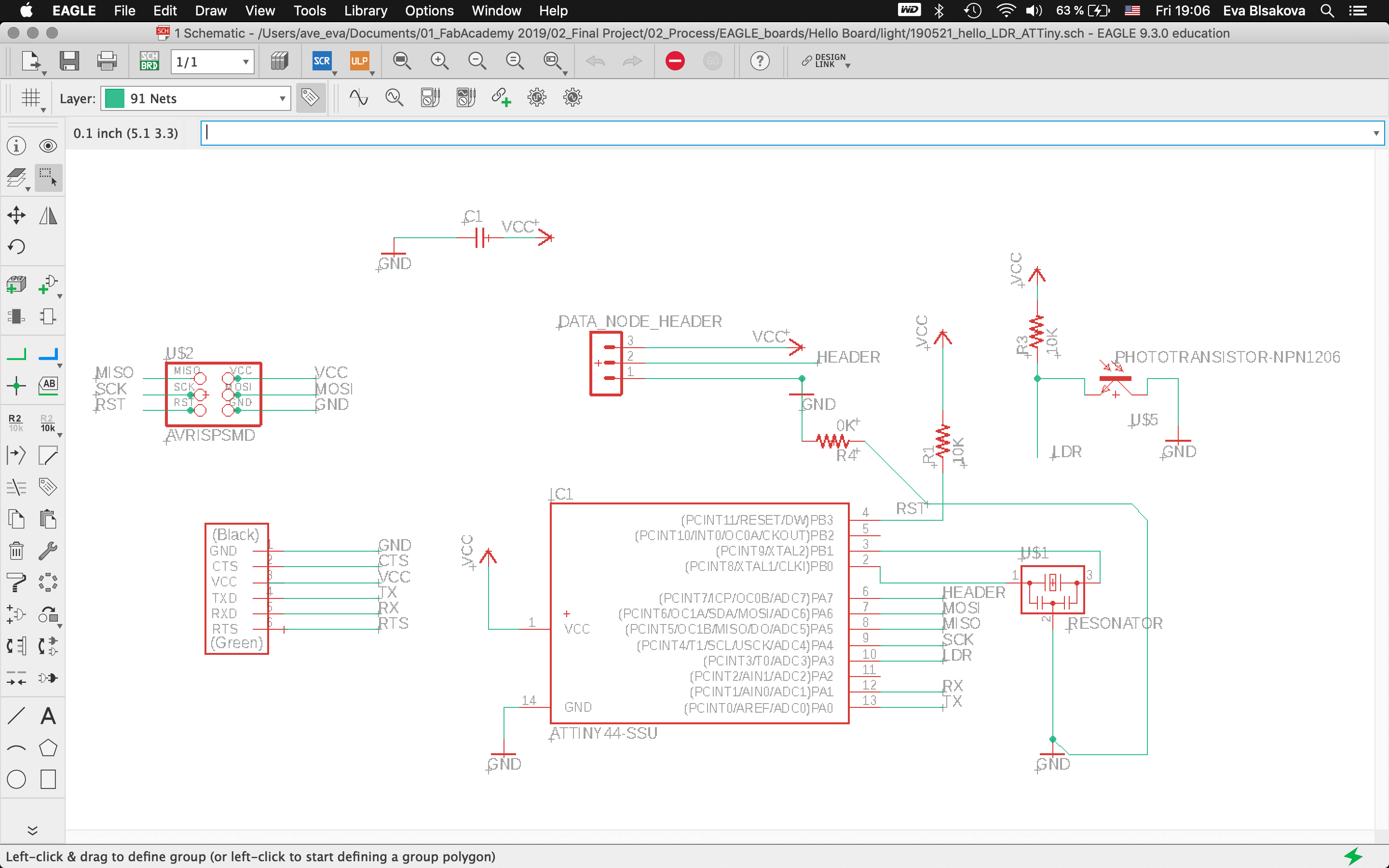
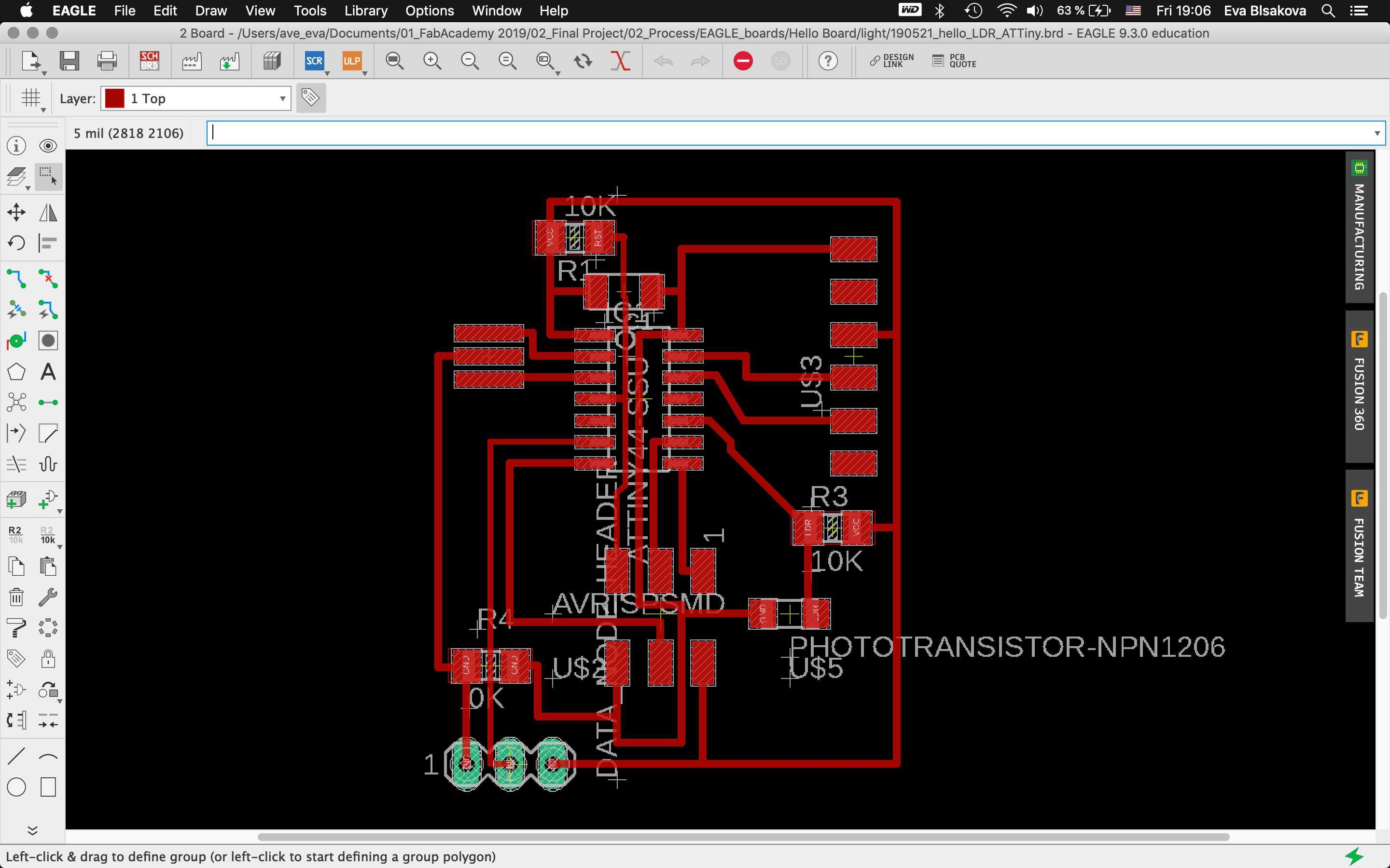
#eaglepcbdesign
#labeledPCBdesign - holes, outline, traces ready to be milled
#pcbdesign #labeled I had to introduce a jumper and make some wires thiner so check out the second variant.
#milling
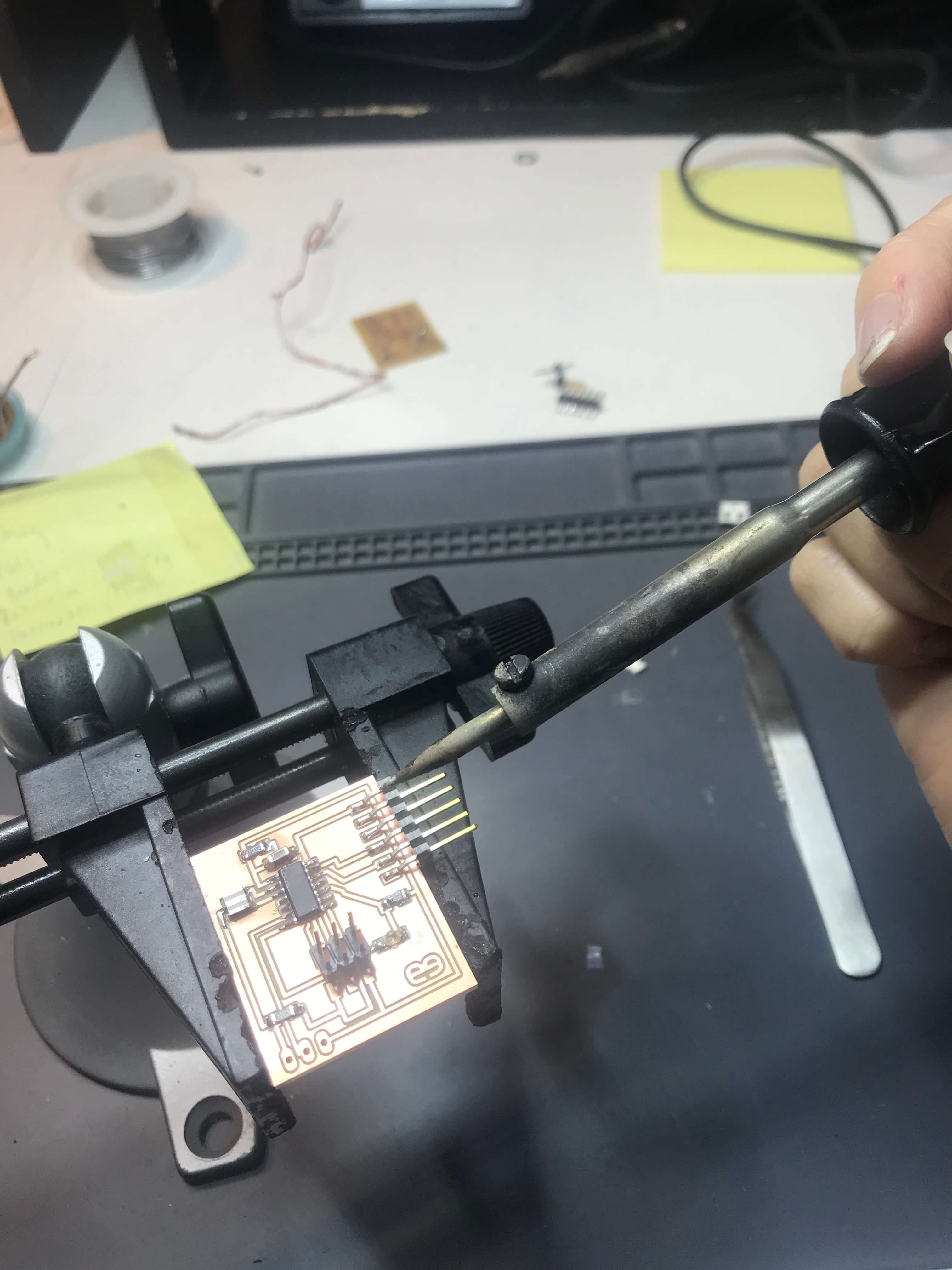
#soldering
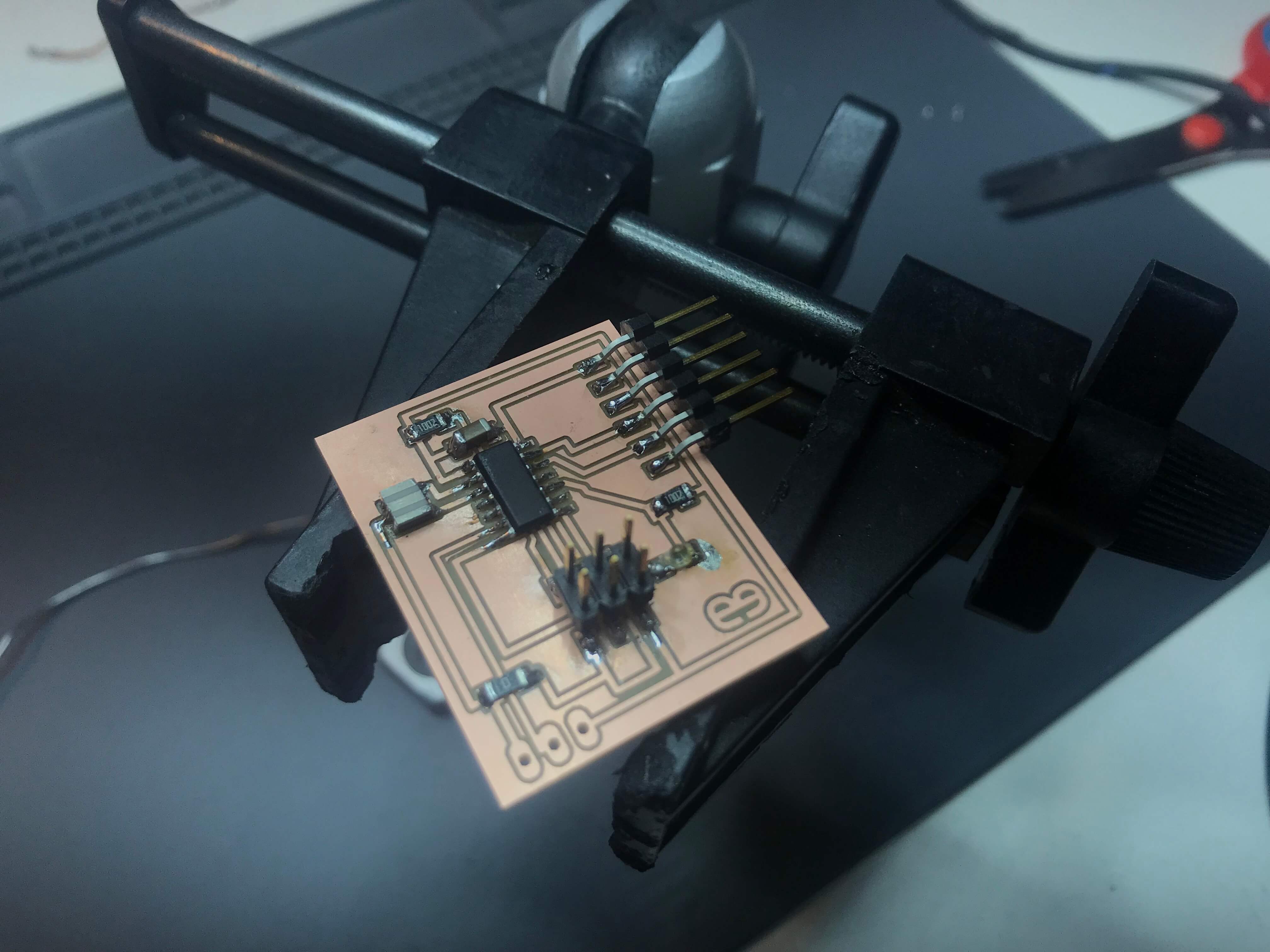
#heroshot
#check - with multimeter we went trough all the connections on the board to see if everything is connected properly to check for the continuity of the circuits. so its important to check the boards continuity before and after soldering. Everything looks good.
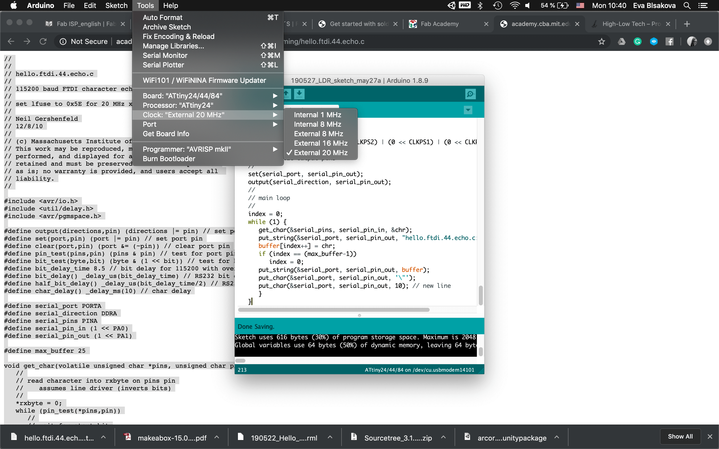
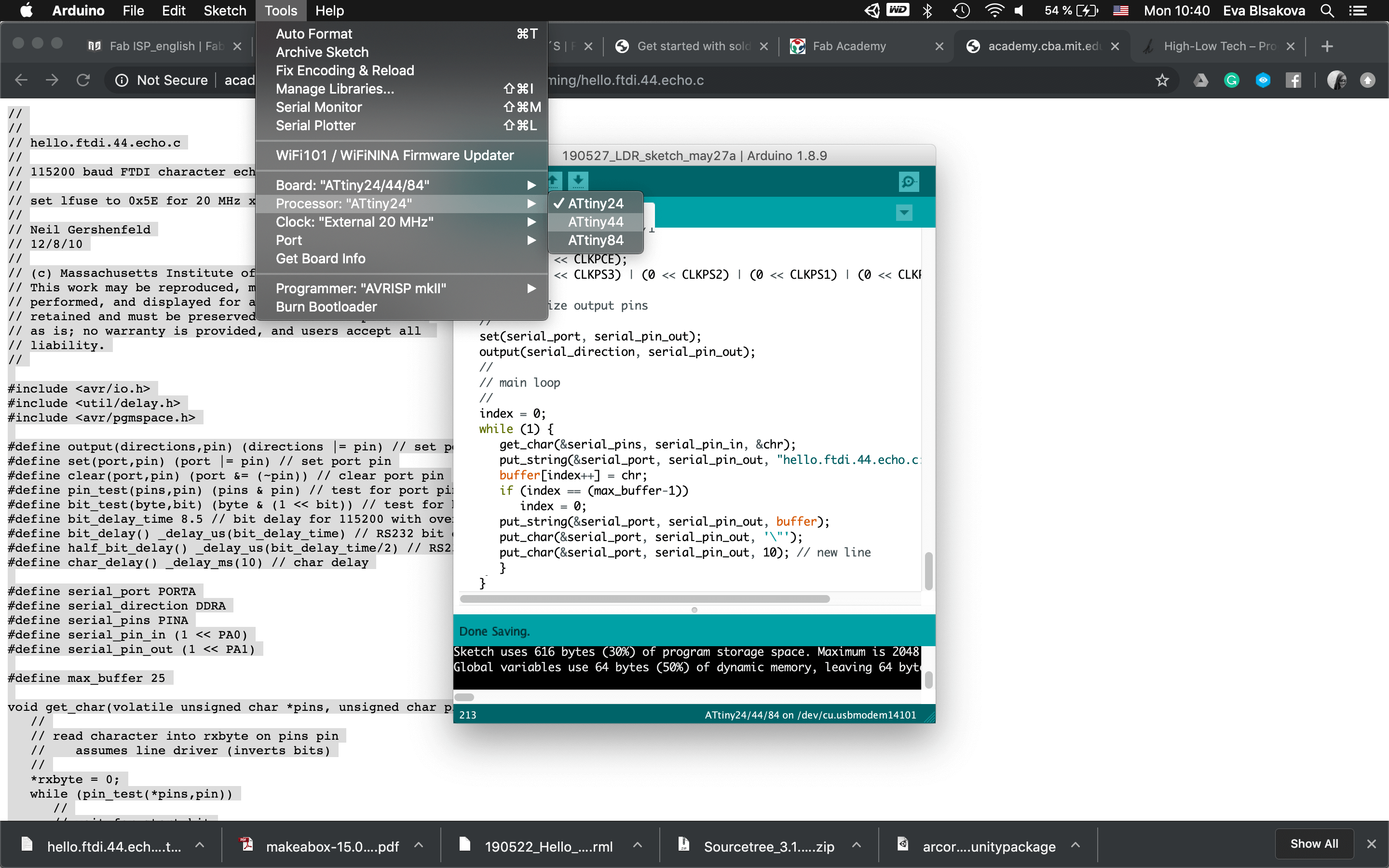
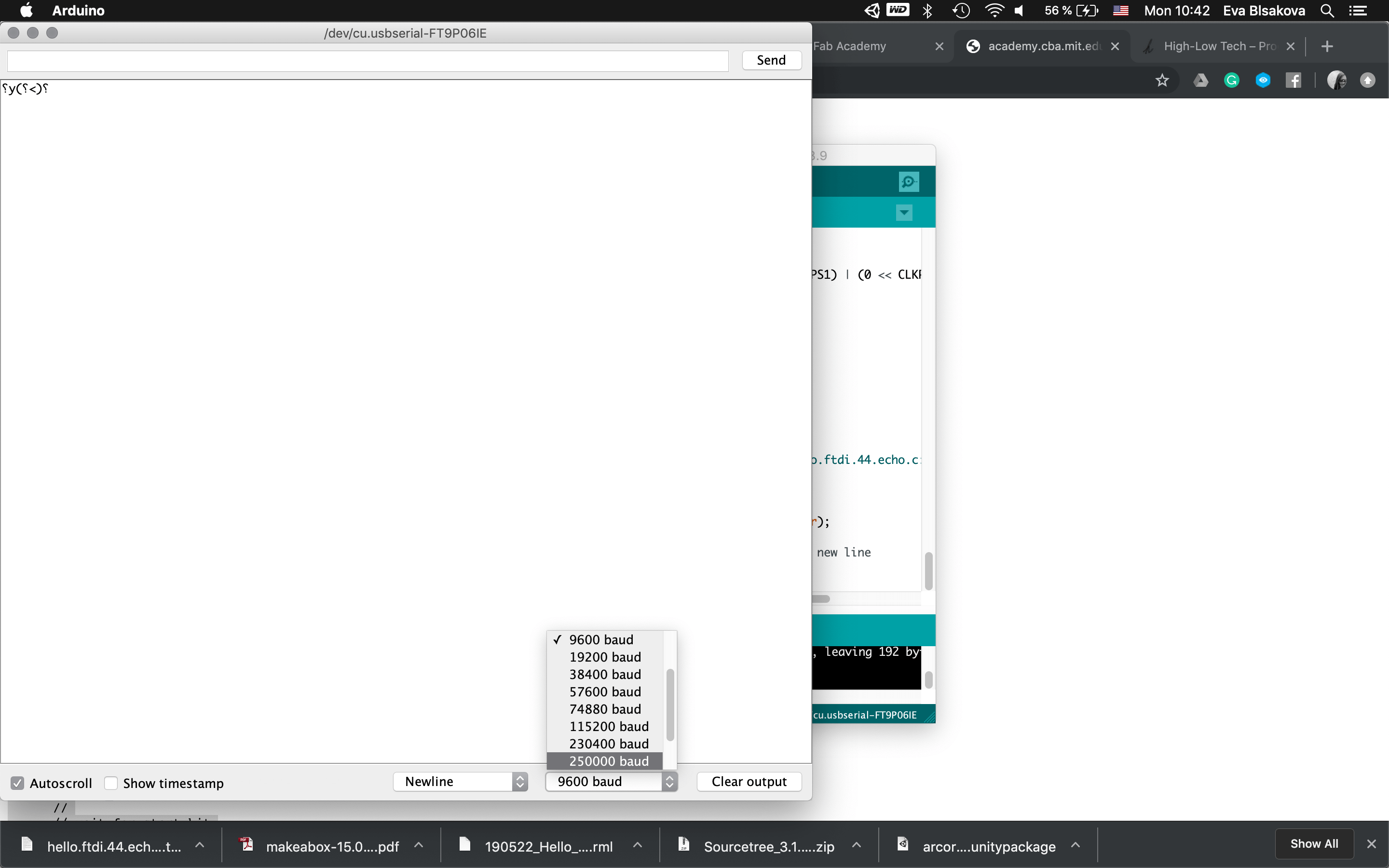
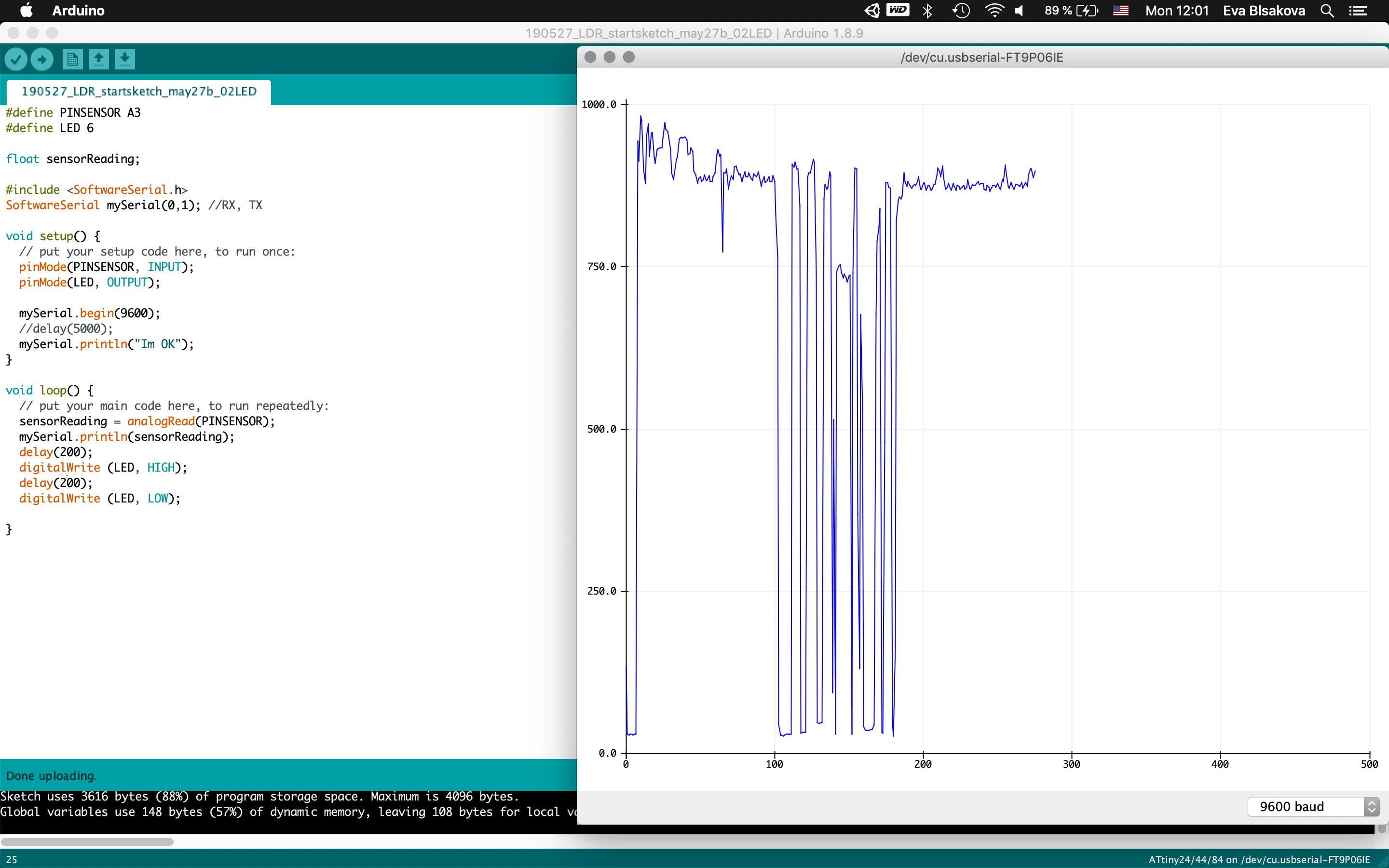
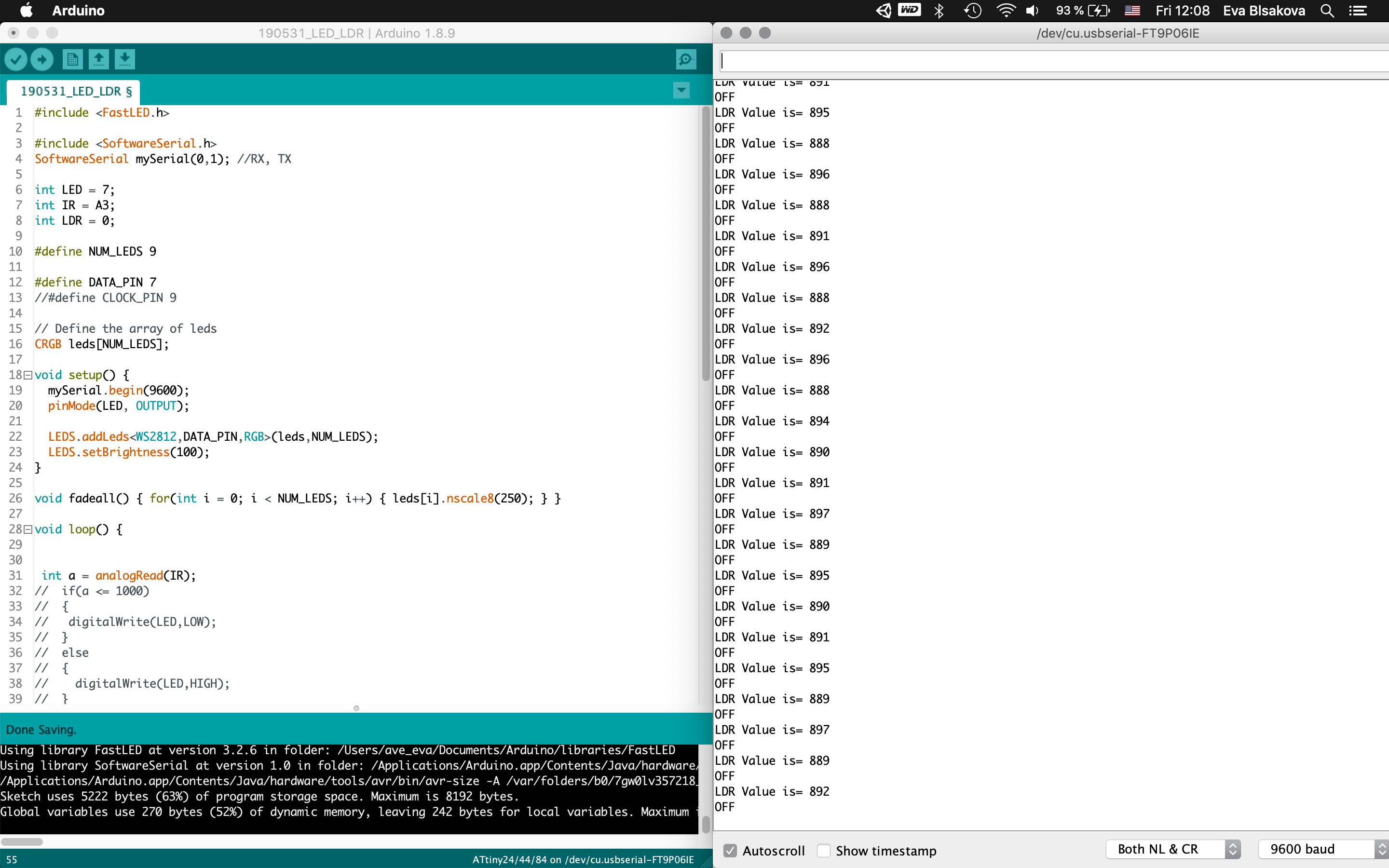
#programming LDR sensor:So connect the board with FTDI, ISP, check the ports, install libraries (this I did already when working on the upper mentioned tutorial)…Fisrt Burn Bootloader -if we want to make our micro-controller being programmable this is the first thing needs to be done before programming. Then I wrote the code using the Arduino IDE. Check the pins which are you connecting with your chip. For the code part - there were some examples already as you can see previously I tested the LDR sensor with the tutorial upper mentioned. This was working with the LED on the breadboard as for testing, my aim was to use a NeopixelLEDstrip for my final project and for that I had to use ATtiny84. So for next step I resoldered the chip and changed ATtiny44 for ATtiny84 to continue. Than the code part again. It was necessary to install neopixel libraries, the same way trough the Library manager inside the Arduino. it comes with premade sketch examples so I took one too and adjusted the code a bit. For using ATtiny84 it was needed to change Serial to mySerial and mySoftwareSerial all over the code. Checking connections to relevant pins and their usage. what pins is related to what task, check where is the connection for LDR and LEDstrip…Than calibration of the sensor part… It's pretty simple, it reads the value from the LDR and if it's below 975 it lights up the LED. Why 975? I tested the LDR by reading and printing the values on serial monitor it reads and I noticed when I cover the LDR the values are always below 975. The process you can see screenshoted below and at the end there is also a video demonstrtion. As you can see this part of the assignment is also related to my output design week and following to the final project, so check them out to get more insights!

#videodemonstration + check the final project process
download files
#anotherone
For step response/capacitance I worked with my existing hello board that I designed previously for testing my final project board with ATtiny84 microchip including LDR sensor. As a first step I checked few fab academy projects from past years and also had closer look at this tutorial. Capacitive sensing may be used in any place where low to no force human touch sensing is desirable. An Arduino and the library may be used to sense human touch through more than a quarter of an inch of plastic, wood, ceramic or other insulating material (not any kind of metal though), enabling the sensor to be completely visually concealed. My aim is to explore possibilities how to switch on/off my lamp using capacitance.
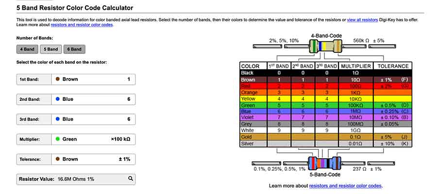
Than I needed to choose the right resistor and for checking its value in case you dont know it you can use this website
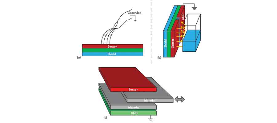
#conductive explained