Final Project
This week I worked on defining my final project idea and started to getting used to the documentation process.
Video
Concept
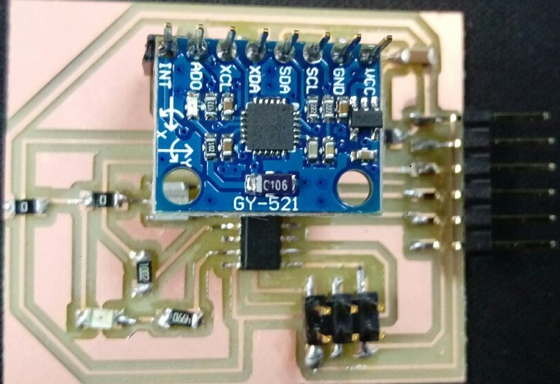
Dragon Robot is a gesture controlled robot using an accelerometer to detect the hand movements & Bluetooth modules for circuits to communicate with each other. I have used Attiny microcontrollers & two DC motors. I wanted to make a dragon robot because I am interested in robotics & I like dragons. It can be used to encourage others to learn more about robotics. Applications and implications week has some details like the cost.
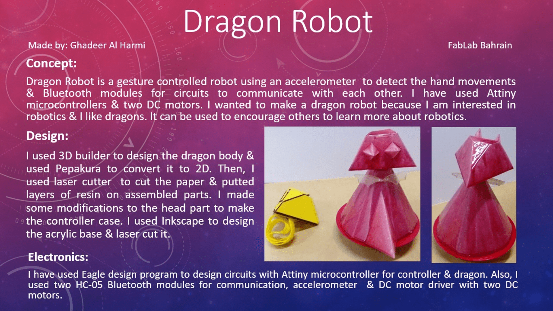
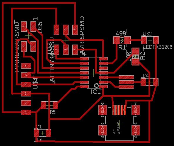
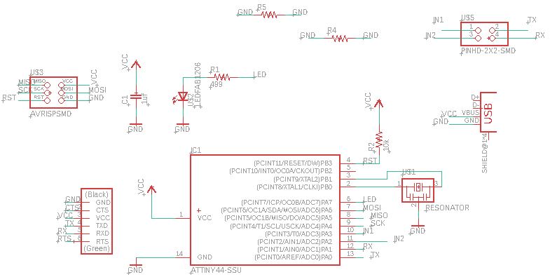
Circuit Design
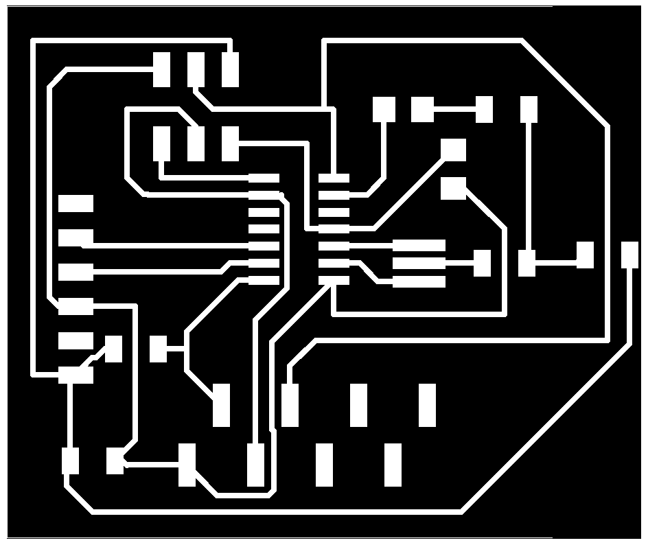
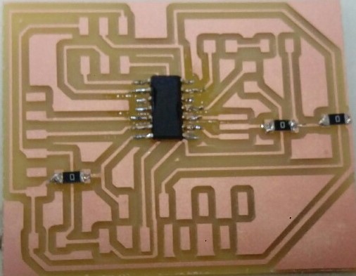
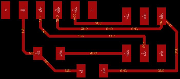
I needed to make two circuits, one for the dragon & the other for the controller. Circuits are based on an Attiny44 & Attiny84 microcontroller with a 20MHz crystal. I designed the circuit using eagle. The circuit consists of the following major copmonents: The microcontroller,a serial header, a power in header, spi programming header and the headers. I created the scehmatic and pcb board on eagle. Exported the images in GIMP & added borders.
This is the electronic part of my project
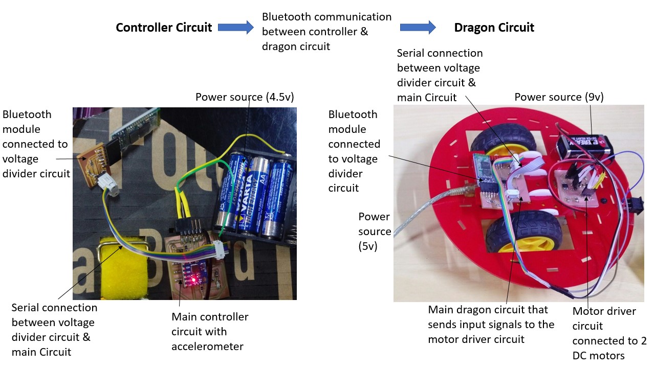
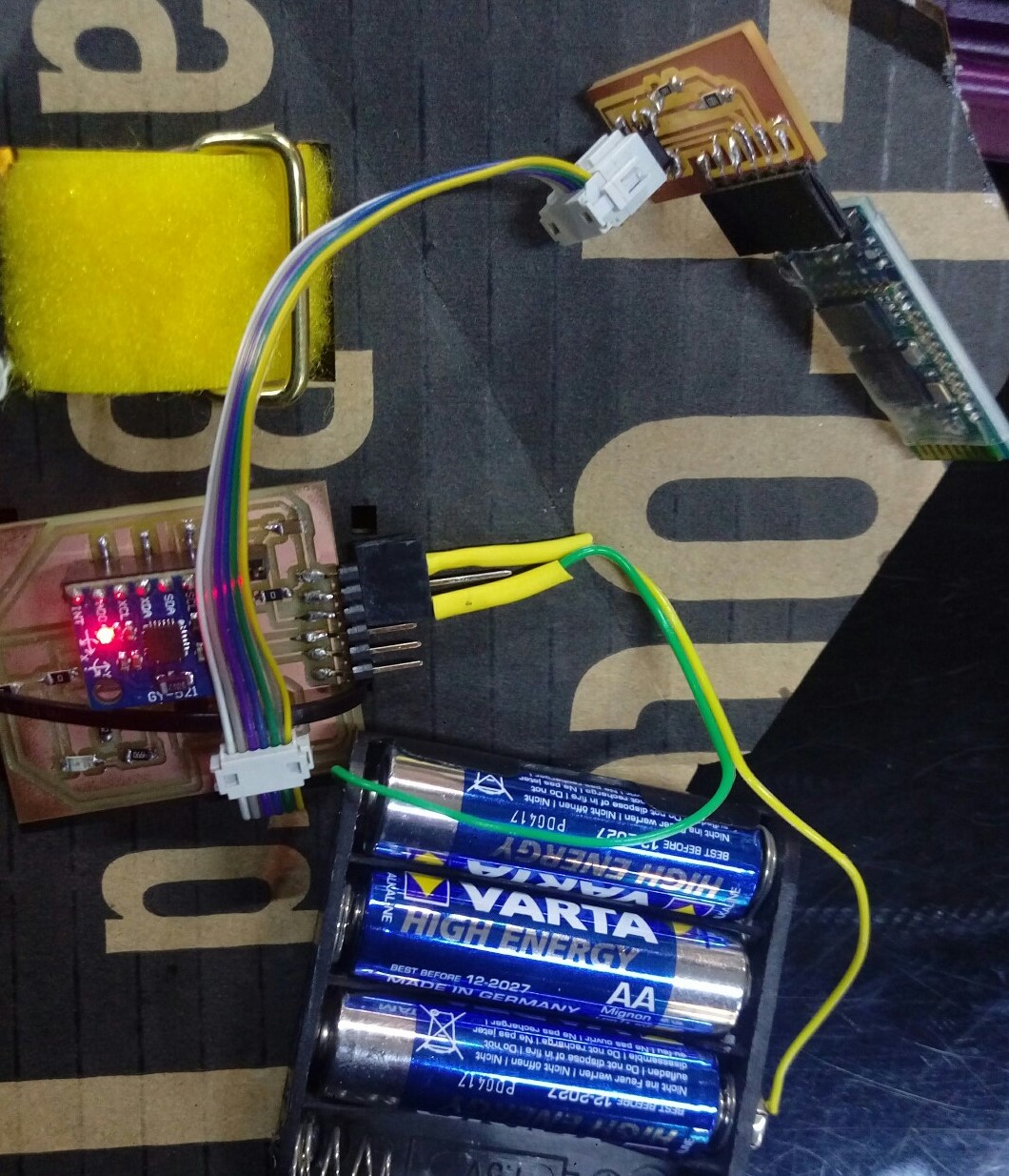
Controller Circuit
Made the circuit in input week .
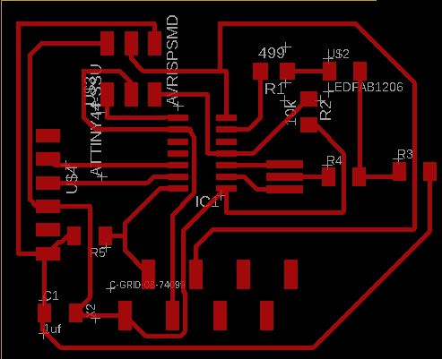
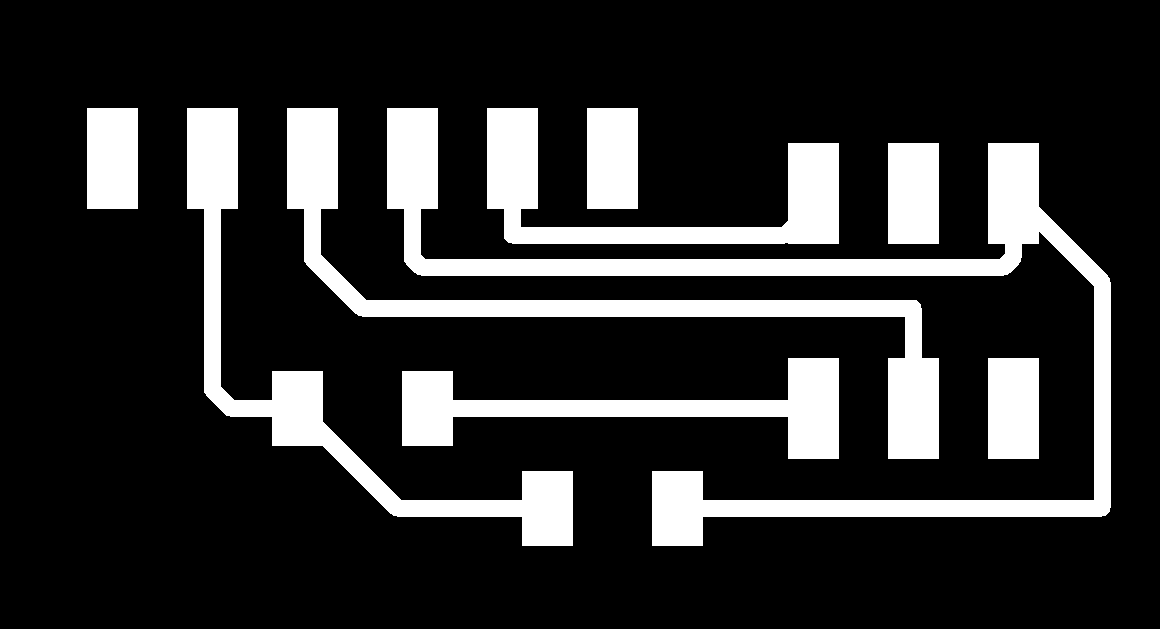
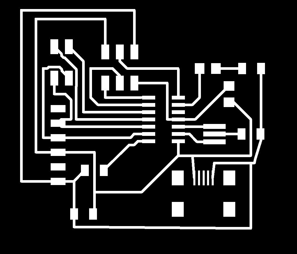
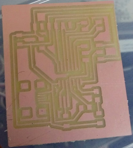
The final tracing & board PNG images
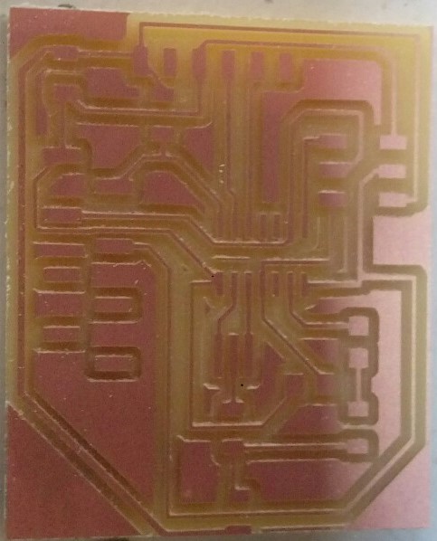
Eagle Board (right click + Save link as)
Eagle Schematic (right click + Save link as)
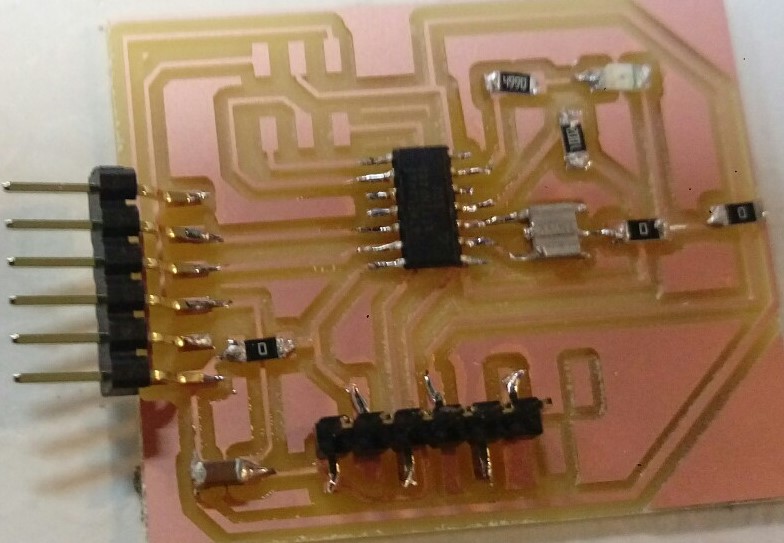
I have connected this circuit to bluetooth module using a circuit that I made for interface and application programming

& I have used 9v battery as a power supply & connected it to LM2596 DC-DC to reduce the voltage to 5v.
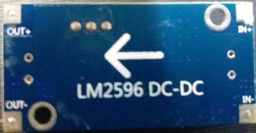
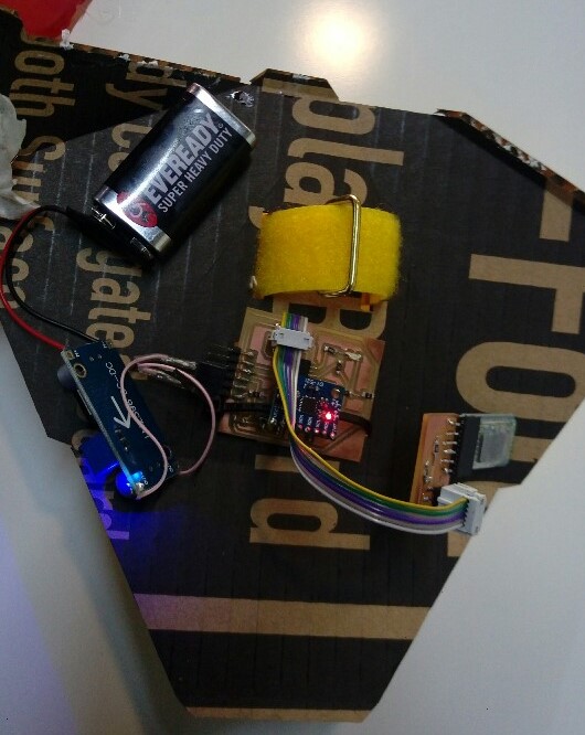
Then I replaced the 9v battery & LM2596 with 3 AA batteries which gives around 4.5v.
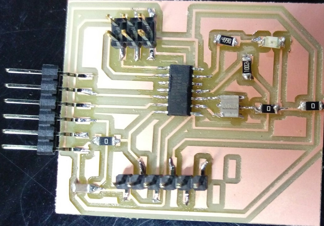
Dragon Circuit
Modified controller circuit by removing accelerometer circuit & adding header for motors & usb port for power.

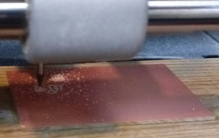
Then milled the circuit & soldered the parts. I followed the same steps as in week 5 .
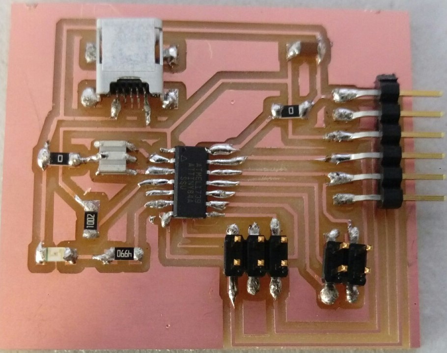
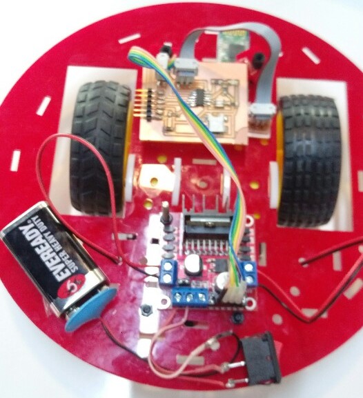
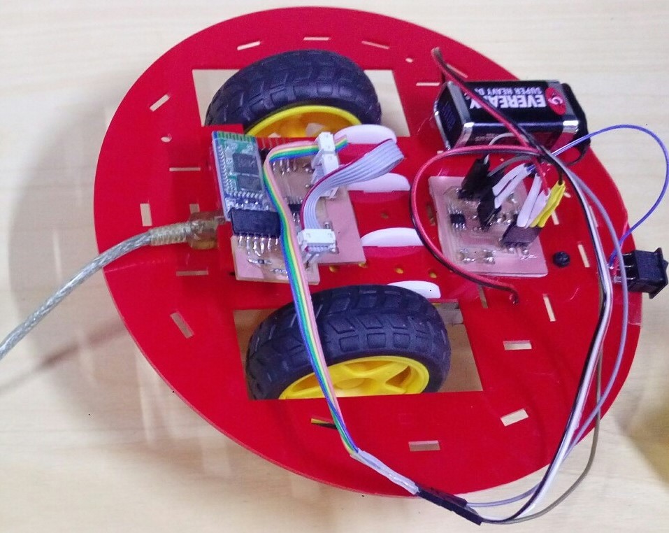
I have connected this circuit to bluetooth module using a circuit that I made & connected a motor driver to the circuit. I connected a 9v battery & a power switch & 2 DC motors to the motor driver. I used a power bank (5v) as a power supply for the main circuit.
Download schematic (right click + Save link as)
Download board (right click + Save link as)
Download board traces (right click + Save link as)
Download board border (right click + Save link as)
Driver Circuit
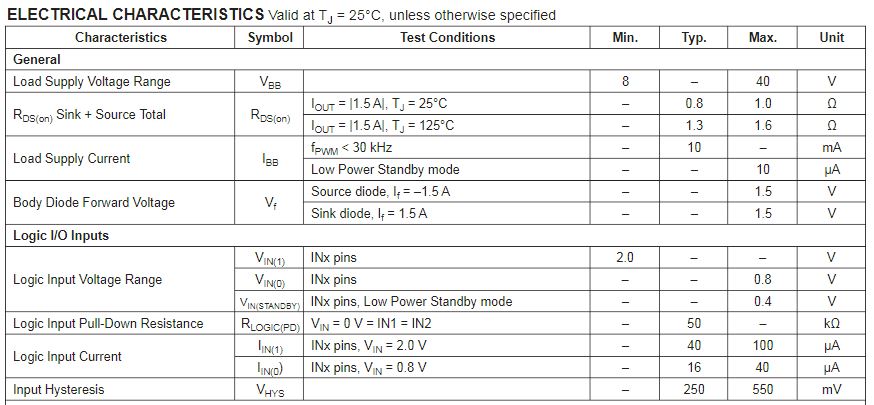
At first I used a made DC motor driver module, but then I made my own motor Driver circuit. I have used Neil circuit as a refrence. I have used A4953 Full-Bridge DMOS PWM Motor Drivers & this is it’s datasheet . A4953 is provided in a low-profile 8-pin SOICN package (suffix LJ).
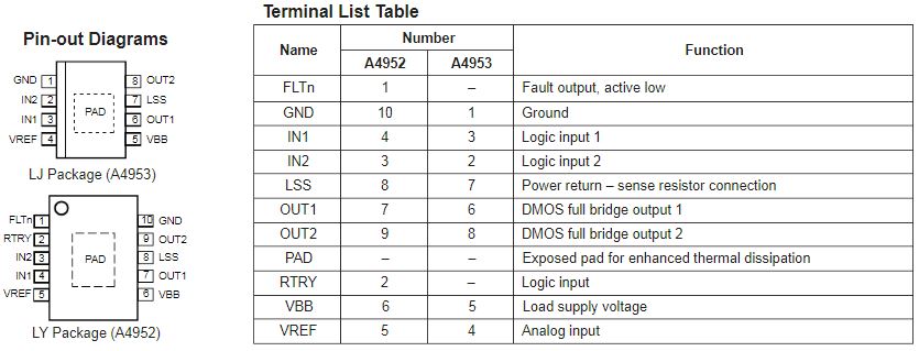
The output drivers are all low-RDS(on) , N-channel DMOS drivers that feature internal synchronous rectification to reduce power dissipation. The current in the output full bridge is regulated with fixed off-time pulse width modulated (PWM) control circuitry. The IN1 and IN2 inputs allow two-wire control for the bridge.
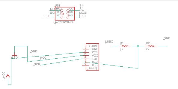
I have added 2 A4953 driver, 4 capacitors (used same values as Neil, 2 1uF & 2 10uF), 4 headers (1 for input signals, 1 for output signals, 1 for power supply, 1 for Vref), a power source & ground. Att some parts I needed less pins for header but I used 4 pin header for more stability.
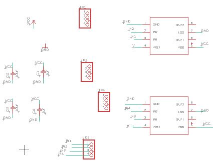
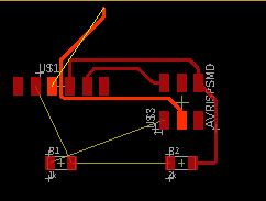
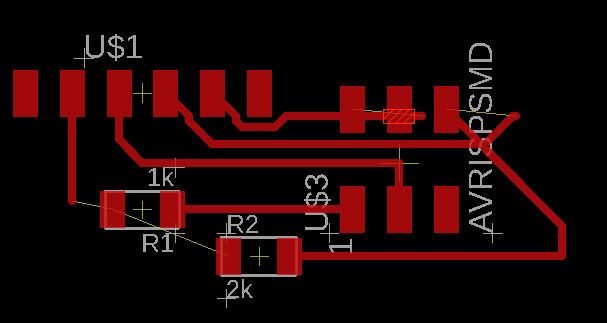
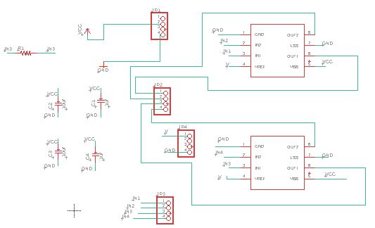
Then, I started connecting them but after several tries I had to add a jumper (0 ohm resistor) to connect all parts).

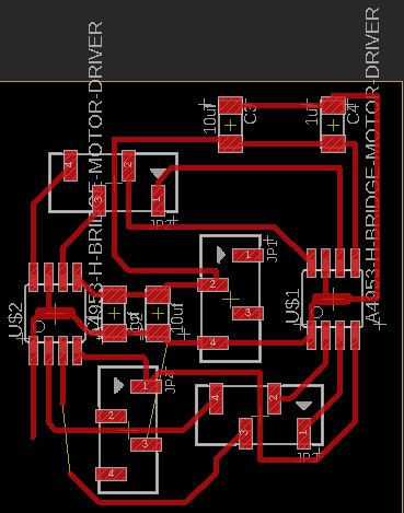
& this is the final connection
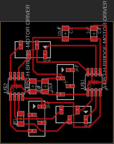
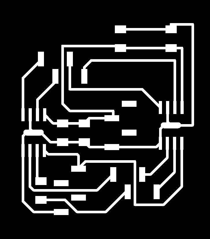
& these are the images I used to create the rml files.

Download schematic (right click + Save link as)
Download board (right click + Save link as)
Download board traces (right click + Save link as)
Download board border (right click + Save link as)
The minimum load supply voltage the driver needs is 8v that’s why I used a 9v battery.
And this is how the circuit looks like.
Intial testing with the new driver circuit
Final testing
Code
I combined & modified the codes I used in previous weeks like input week & networking week & this website for DC motor control.
Controller Code
#include <TinyWireM.h>
#include <SoftwareSerial.h>

SoftwareSerial mySerial(PA4, PA5);
int state = 0;
#ifdef DEBUG
#endif

int accelX, accelY, accelZ;
char mpu = 0x68;
int dirct = 0  ;
SoftwareSerial Monitor(PA1, PA0);  // We will only use Tx on PortB 4

void setup() {
  Monitor.begin(9600);
  TinyWireM.begin();
  delay(1000);

  // We need to do three things.  1. Disable sleep mode on the MPU (it activates on powerup).  2. Set the scale of the Gyro.  3. Set the scale of the accelerometer
  // We do this by sending 2 bytes for each:  Register Address & Value
  TinyWireM.beginTransmission(mpu);
  TinyWireM.write(0x6B); //  Power setting address
  TinyWireM.write(0b00000000); // Disable sleep mode (just in case)
  TinyWireM.endTransmission();
  TinyWireM.beginTransmission(mpu);
  TinyWireM.write(0x1B); // Config register for Gyro
  TinyWireM.write(0x00000000); // 250° per second range (defau<)
  TinyWireM.endTransmission();
  TinyWireM.beginTransmission(mpu); //I2C address of the MPU
  TinyWireM.write(0x1C); // Accelerometer config register
  TinyWireM.write(0b00000000); // 2g range +/- (defau<)
  TinyWireM.endTransmission();
  mySerial.begin(38400); // Default communication rate of the Bluetooth module
}

void loop() {
  getAccel();
  getDirrection();
Monitor.println(dirct);
      mySerial.println(dirct);

 mySerial.write('dirct');
}

void getDirrection(){

if (accelX>5000) //front
{
 dirct = 1;

}
if (accelX<-5000) //back
{

  dirct = 2;
}
if (accelY>5000) //left
{

  dirct = 3;
}
if (accelY<-5000) //right
{

  dirct = 4;
}
if(accelX < 5000 && accelX > -5000 && accelY < 5000 && accelY > -5000){ //stop
dirct = 0;

}
}


void getAccel() {
  TinyWireM.beginTransmission(mpu); //I2C address of the MPU
  TinyWireM.write(0x3B); //  Acceleration data register
  TinyWireM.endTransmission();
  TinyWireM.requestFrom(mpu, 6); // Get 6 bytes, 2 for each DoF
  accelX = TinyWireM.read() << 8; // Get X upper byte first
  accelX |= TinyWireM.read();     // lower
  accelY = TinyWireM.read() << 8; // Get Y upper byte first
  accelY |= TinyWireM.read();     // lower
  accelZ = TinyWireM.read() << 8; // Get Z upper byte first
  accelZ |= TinyWireM.read();     // lower
}
Dragon Code
#include<SoftwareSerial.h>
SoftwareSerial mySerial(PA4, PA5);
int dirct ;
int IN1 = PA3;  // MCU Digital Pin 9 to IN1 on L298n Board
int IN2 = PA2;  // MCU Digital Pin 8 to IN2 on L298n Board
int IN3 = PA1;  // MCU Digital pin 7 to IN3 on L298n Board
int IN4 = PA0;  // MCU Digital pin 6 to IN4 on L298n Board
SoftwareSerial Monitor(PA1, PA0);
void setup()
{
Monitor.begin(9600);
  //pinMode(ENA, OUTPUT); //Set all the L298n Pin to output
  //pinMode(ENB, OUTPUT);
  pinMode(IN1, OUTPUT);
  pinMode(IN2, OUTPUT);
  pinMode(IN3, OUTPUT);
  pinMode(IN4, OUTPUT);
  mySerial.begin(38400); // Default communication rate of the Bluetooth module
}

void loop()
{

 if(mySerial.available()){ //Checks whether data is comming from the serial port
    dirct = mySerial.read();
    Monitor.println(dirct);
 }

 // Controlling the Motor
 if (dirct == 1) {
  // Forward
  digitalWrite(IN1, HIGH); // Turn HIGH motor A
  digitalWrite(IN2, LOW);
  digitalWrite(IN3, HIGH); // turn HIGH motor B
  digitalWrite(IN4, LOW);  // To set the turning speed to 200 out of possible range 0 to 255
 }
   if (dirct == 2) {
  // Back

  digitalWrite(IN1, LOW);
  digitalWrite(IN2, HIGH);
  digitalWrite(IN3, LOW);
  digitalWrite(IN4, HIGH);

 }

 if (dirct == 3) { //right
  digitalWrite(IN1, HIGH);
  digitalWrite(IN2, LOW);
  digitalWrite(IN3, LOW);
  digitalWrite(IN4, LOW);
 }
 if (dirct == 4) {//left


  digitalWrite(IN1, LOW); // Turn the motor off
  digitalWrite(IN2, LOW); // Turn the motor off
  digitalWrite(IN3, HIGH); // Turn the motor off
  digitalWrite(IN4, LOW); // Turn the motor off
 }

 if (dirct == 0) {//stop


  digitalWrite(IN1, LOW); // Turn the motor off
  digitalWrite(IN2, LOW); // Turn the motor off
  digitalWrite(IN3, LOW); // Turn the motor off
  digitalWrite(IN4, LOW); // Turn the motor off
 }

}
Dragon Design
The biggest challange was deciding the easiest and most efficeint way to make the dragon.
Dragon Body
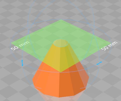
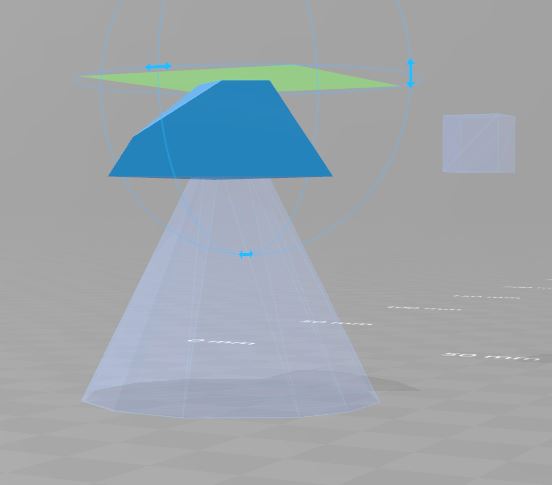
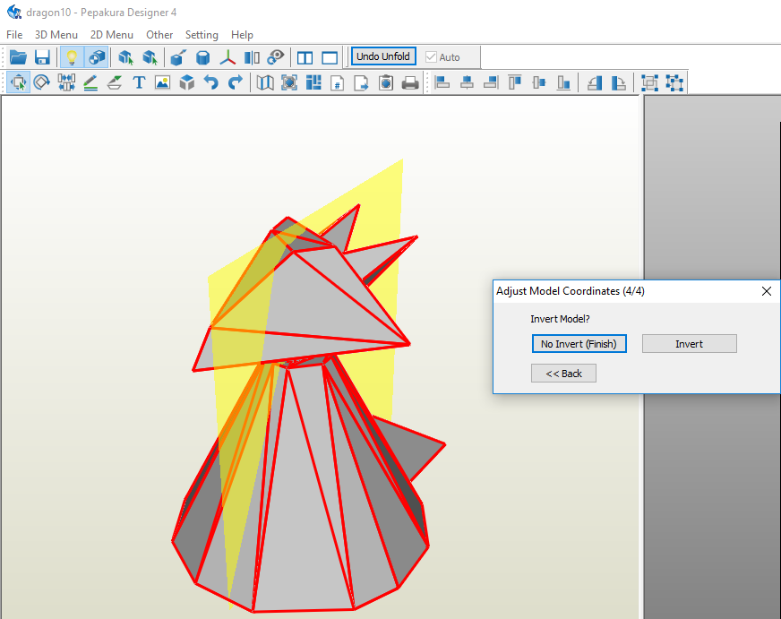
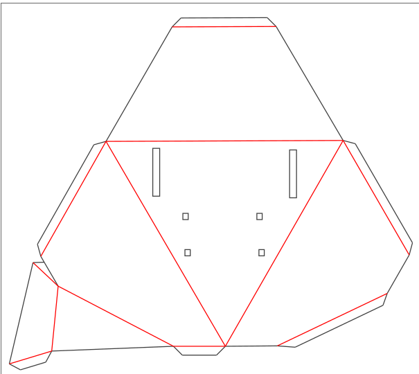
I made a new simple design using 3D Builder for the dragon.
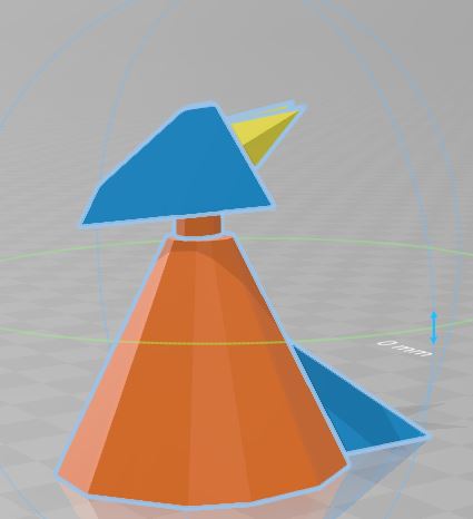
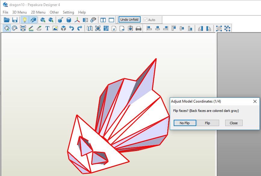
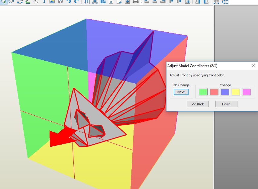
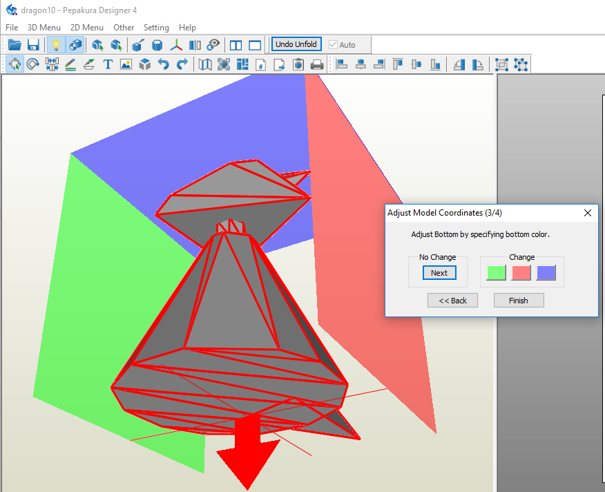
Then, I exported it in Pepakura & sprcified the directions & saved the file in dxf format.
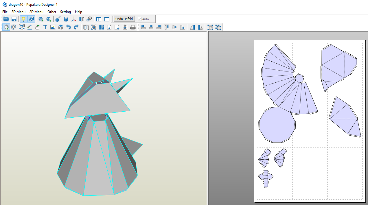
After that, I opened the dxf file using Inkscape & arranged the parts based on laser cutter size.
DXF File Download (right click + Save link as)
pdf File 1 Download (right click + Save link as)
pdf File 2 Download (right click + Save link as)
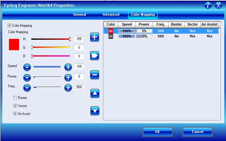
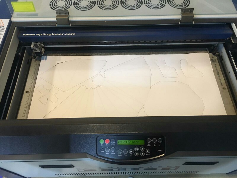
The dxf file generated by Pepakura, has dark grey colour for the parts that needs to be cut & red for the parts that need scoring. Set the laser cutting settings & laser cut the parts on a bit think paper. Used mat board settings as a refrence & modified them to cut the paper.
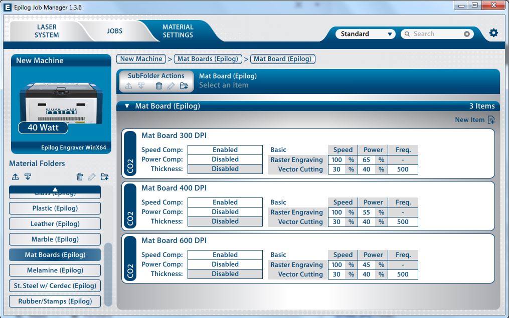
For the parts to be cut through I used speed 100 & power 30 & for scoring the parts than need to be bend I used speed 100 & power 5 both at frequency 500.
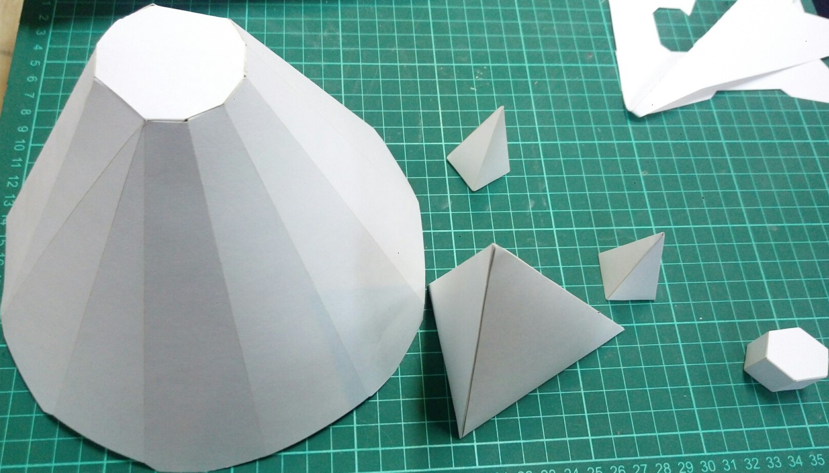
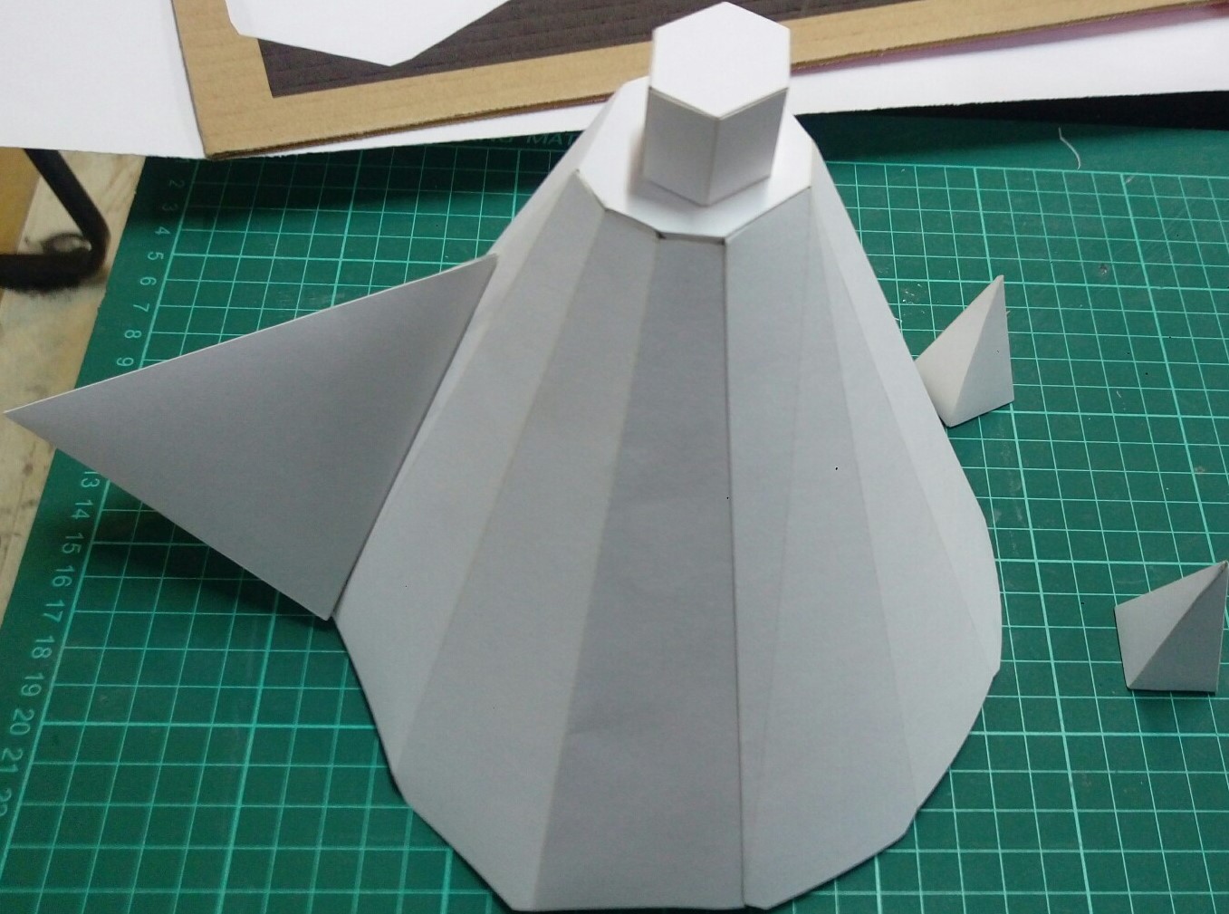
Assembeled the parts using stick glue.
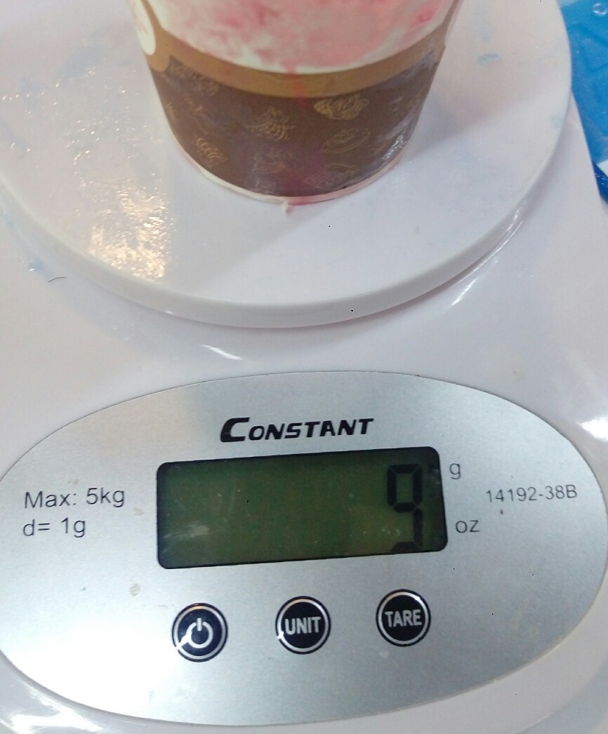
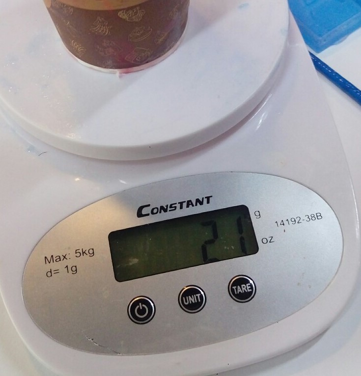
Made red colour resin by mixing 70% of resin & 30% of hardener (using weight calculation). Added few drops of colour & mixed them well.
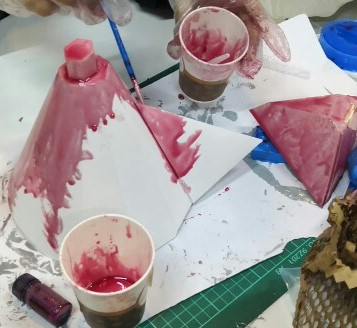
Started painting it with resin & it dried within less than a day.
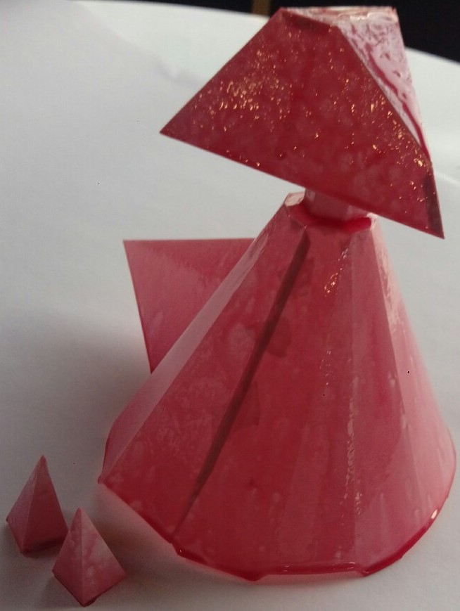
After it dried, I applyed a second layer.
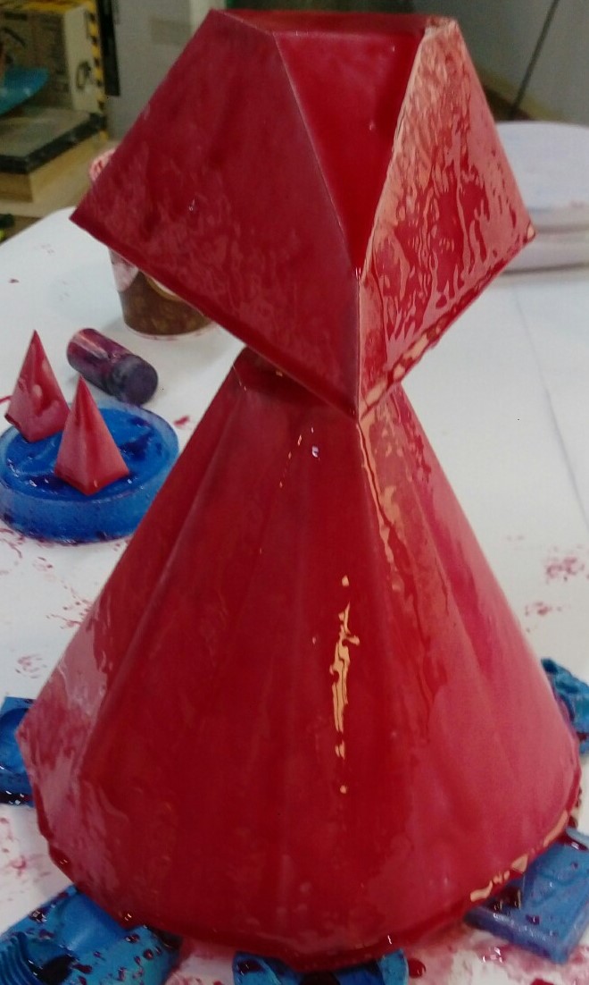
After drying
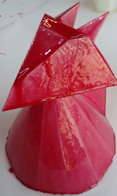
As a final touch I made wings from molds that I made before in week 10 .
DXF File Download (right click + Save link as)
PDF File part1 Download (right click + Save link as)
PDF File part2 Download (right click + Save link as)
Dragon Base Design
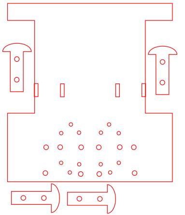
Important factors to consider in my design was the size of wheels & circuits to allow comfortable usage and the assembly method. I used Inkscape to design the base. At first, I made it in rectangle shape. I designed half of the shape then duplicated it & merged them. Made slots for motors support & added holes for wires & support wheel.
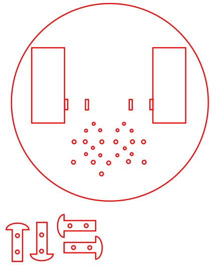
Then changed the shape to circle to give support to the dragons body & added more slots & holes to secure other parts.
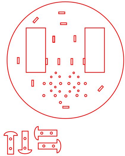
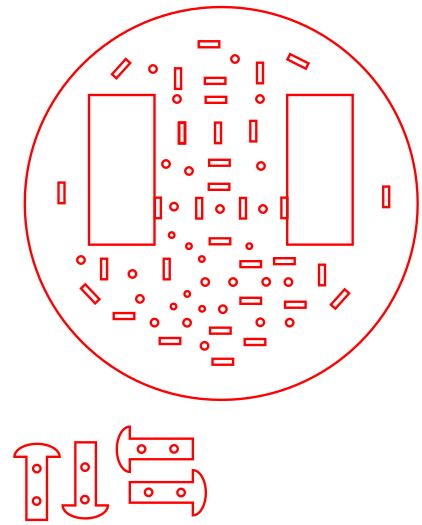

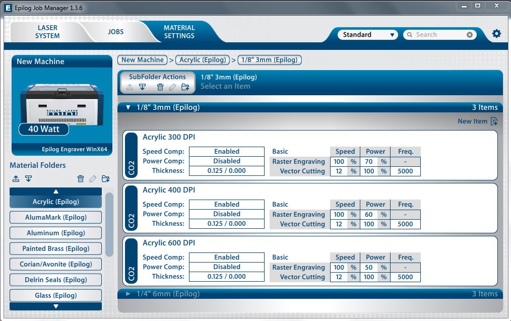
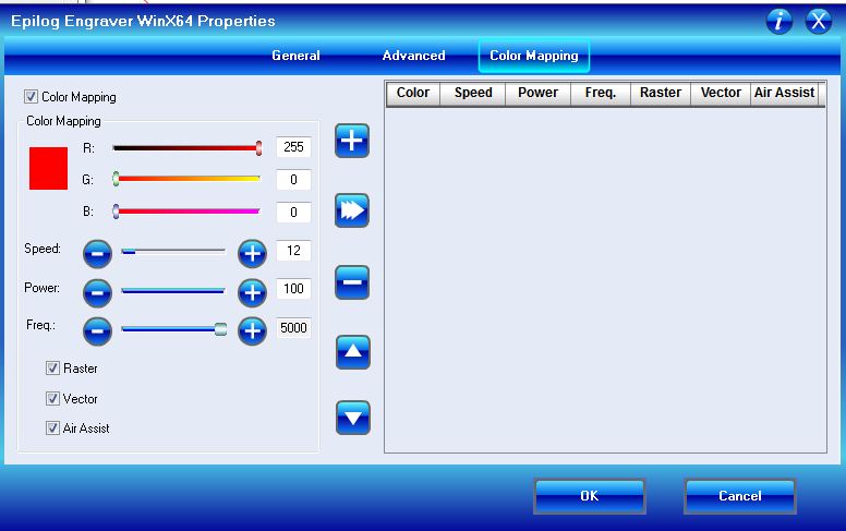
Set the laser cutting settings & laser cut the parts on acrylic. Used acrylic settings as a refrence to cut the base. I used speed 12 & power 100 with frequency 5000.
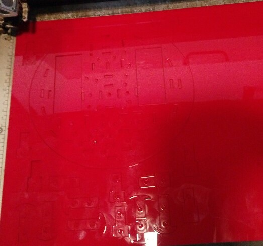
SVG File Download (right click + Save link as)
PDF File Download (right click + Save link as)
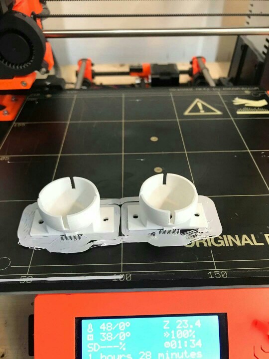
I needed an extra wheel for balance. Found a 3D pingpong ball holder design.
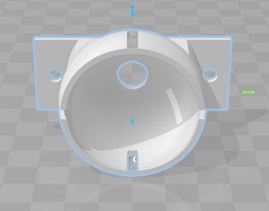
Pingpong ball size 40 mm & the ball we have is 30 mm. 3D printing steps & limitation can be found in this link . Printed it with 75% of original design size but was a bit small. 77% of original size was a perfect match.
STL File Download (right click + Save link as)
After assembly
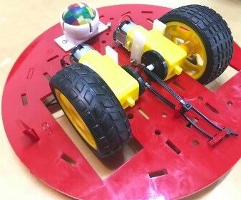
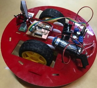
Modified arrangement
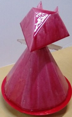
Dragon Controller
I used the head design generated from Pepakura & made some modifications to it. I adeed slots for the yellow strap & holes to fasten the accelerometer circuit.
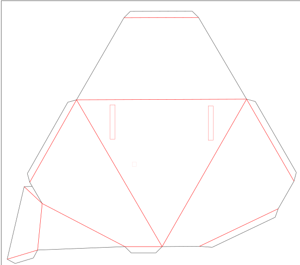
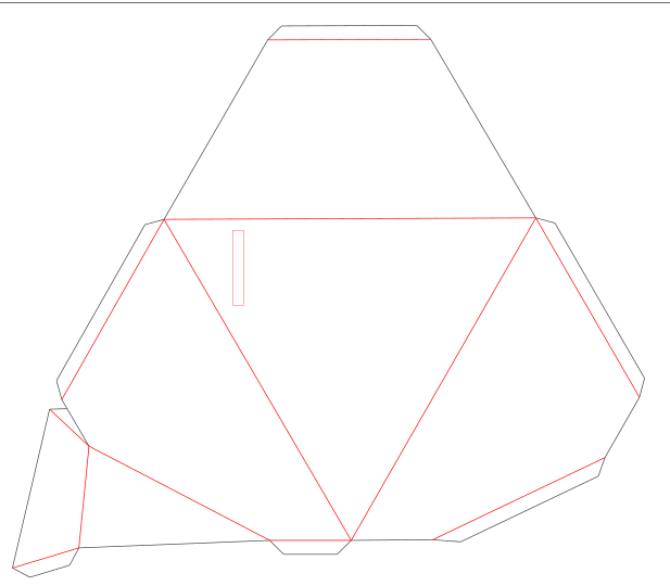
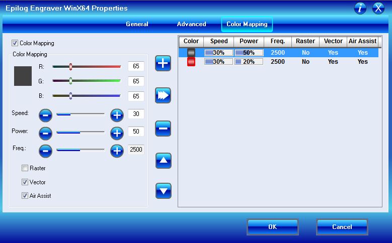
I laser cut it on mat board but changed the original settings a bit. For the parts to be cut through I used speed 30 & power 50 & for the parts than need to be bend I used speed 30 & power 20 both at frequency 2500.
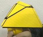
I fastened the strap & the accelerometer circuit. then, glued the the head parts together.
SVG File Download (right click + Save link as)
PDF File Download (right click + Save link as)
Final Looks
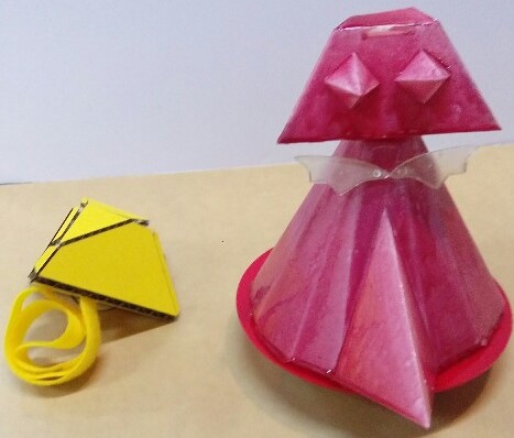

Dragon Robot by Ghadeer Alharmi is licensed under a Creative Commons Attribution 4.0 International License.