While networking is fine when connecting boards with each other, the same techniques and protocols are unsuitable for use with humans. And even though one could attach buttons and displays to their devices, they are often not very convenient. However, nowadays almost everyone has a smartphone or a PC (or at least access to one), which already is a very convenient input device, so why not this instead of clunky buttons and small LCD displays?
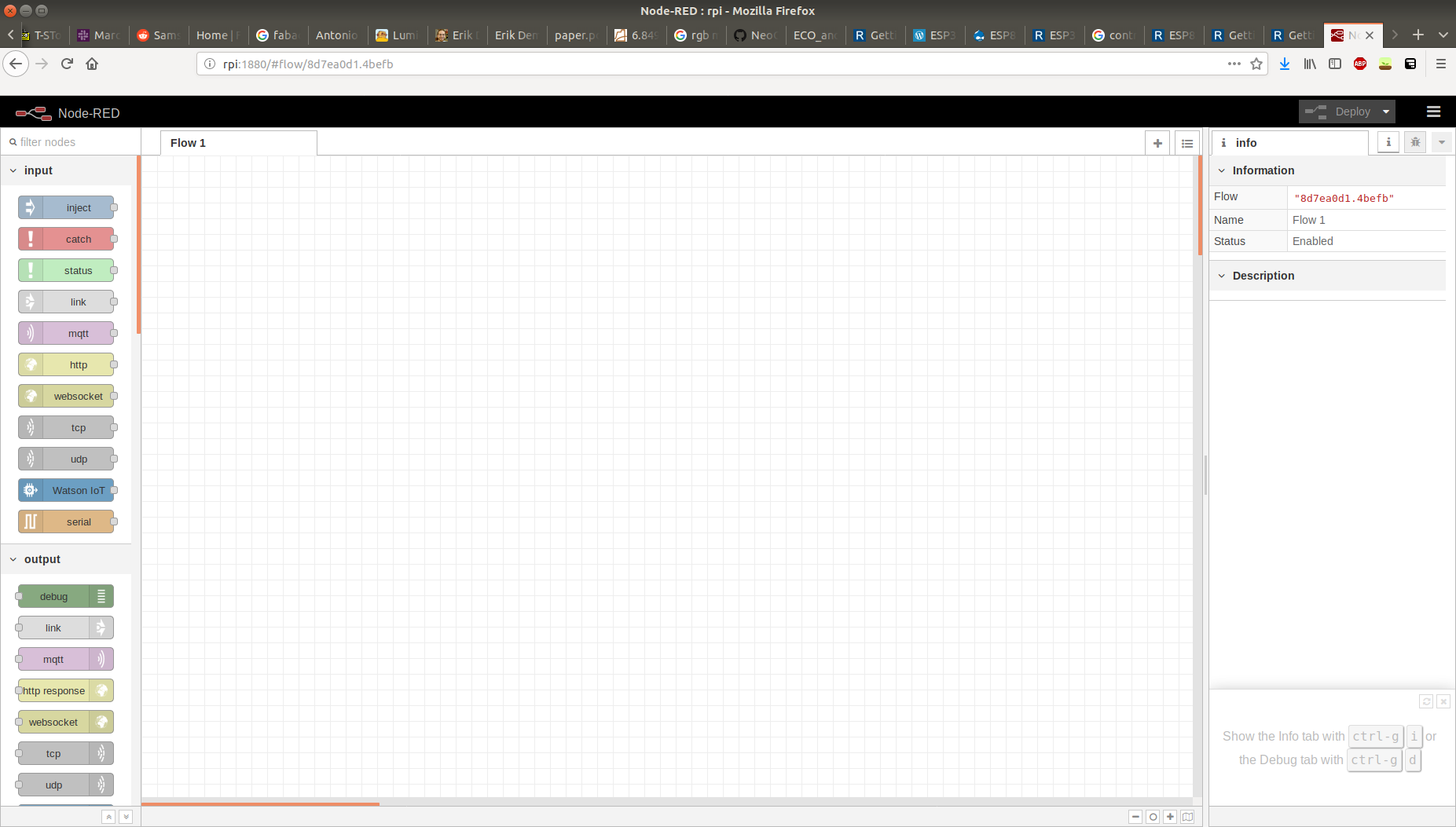
This week, I used Node-RED to setup a webserver on a RaspberryPi 3. This webserver provides a convenient user interaface to control various other devices which are connected to the Pi via the MQTT protocol. One of those devices is a 32x32 RGB LED matrix display controlled by an ESP32.
Setting up the Pi
First, I installed an MQTT broker and Node-RED. As broker, I used Mosquitto, which can be installed via
$ sudo apt-get update && sudo apt-get install mosquitto mosquitto-clients
To install Node-RED on the Pi, the easiest way is downloading and executing the provided install script as detailed in their getting started guide:
bash <(curl -sL https://raw.githubusercontent.com/node-red/raspbian-deb-package/master/resources/update-nodejs-and-nodered)
This script will update your NodeJS, clean your npm cache, and perform some other tasks. If you want to just install Node-RED, you can install it via npm.
I also installed the Node-RED dashboard, which provides a simple graphical user interface to interact with my nodes:
$ cd ~/.node-red
$ npm install node-red-dashboard
After the installation finished, I used the following commands to make both mosquitto and Node-RED autostart on boot:
$ sudo systemctl enable nodered.service
$ sudo systemctl enable mosquitto.service
Then, I restarted the Pi via
$ sudo reboot
After the Pi is back on, Node-RED should be running at port 1880.
If your Pi's ip address is 192.168.0.123, the dashboard can be found at 192.168.0.123:1880/ui.
To see if mosquitto was installed, run mosquitto -v.
Creating a flow in Node-RED
As a simple example, I created an interface that controls the RGB matrix. Each change in one of the control elements on the dashboard will send a MQTT message to the ESP32, which will update the LED matrix. Behavior like this is modeled via "flows" in Node-RED.
First, I added a tab called "Matrix" that will hold all user interface controls for the LED matrix. Then I added a group to this tab called "color" which will provide controls to light up the matrix in a single color. Next, I added three slider nodes and one MQTT output node, which will act together to forward color changes to the ESP32. Node properties can be edited by double clicking on that node. I gave all three sliders names and specified the mqtt topic they will publish on. For the mqtt output node, I specified the local mqtt broker as server, and left the topic field blank so it will get populated by the message. The three sliders are connected to the mqtt output ndoe. Finally, the flow has to be deployed by clicking on Deploy in the upper right corner.
Programming the ESP32
Fortunately, the ESP32 can be programmed with the Arduino IDE. To do so, I needed to add the following URL as "Additional Boards Manager URLs", under File->Preferences:
https://dl.espressif.com/dl/package_esp32_index.json
I used an ESP32 Dev Module. To use MQTT on the ESP32, I also installed the "PubSubClient" and "EspMQTTClient" libraries via the Arduino library manager. For the RGB LED matrix, I installed a library from github to control it with the ESP32. The code can be found in the download section. Working with MQTT and the PubSubClient library is quite simple. Declare a WiFi connection and a mqtt client:
WiFiClient espClient;
PubSubClient client(espClient);
Then, after setting up the wifi connection, connect to an mqtt server and set a callback for incoming messages:
client.setServer(mqtt_server, 1883);
client.setCallback(callback);
The callback has the following signature:
void callback(String topic, byte* message, unsigned int length);
Running the sketch, the ESP32 connects to the WiFi and waits for messages. Changing the sliders publishes messages on their corresponding topics, which get received and interpreted by the ESP32.

Finally, I modified the code for the ESP32 in order to use it in connection with one of my own boards. I connected one of my output boards via I2C to the ESP32, so that on each arriving MQTT message, the ESP32 sends a message via I2C to my board, which updates the color of its LED accordingly. The modifications needed are minor, because the Arduino library provides an implementation for I2C. On the other side, I reused code from the networking week. You can find all of the code in the download section.


