This week, we were introduced to machines that can cut arbitrary 2D shapes out of material.
As a group, we had to test the kerf, speed, and power of the laser cutter in our lab.
These are important parameters of the laser cutter that need to be kept in mind when working with the machine.
The kerf of the laser is the width of the cut.
It also depends on the material being cut.
Speed and power of the laser are pretty self-explanatory.
The laser cutter in our lab is an Epilog Zing 24, with a work area of 610x305mm.
A tutorial on its operation and more general information is available on our lab page.
First, we created a simple model on which we can test the kerf.
After cutting the parallel lines, we can determine the kerf by shifting the inner parts to one side, measuring the resulting gap, and dividing by the number of cuts.
We made 14 cuts and measured a gap of 1.76mm, therefore the kerf of our laser cutter is about 0.13mm. For this we used a power of 80 and a speed of 50
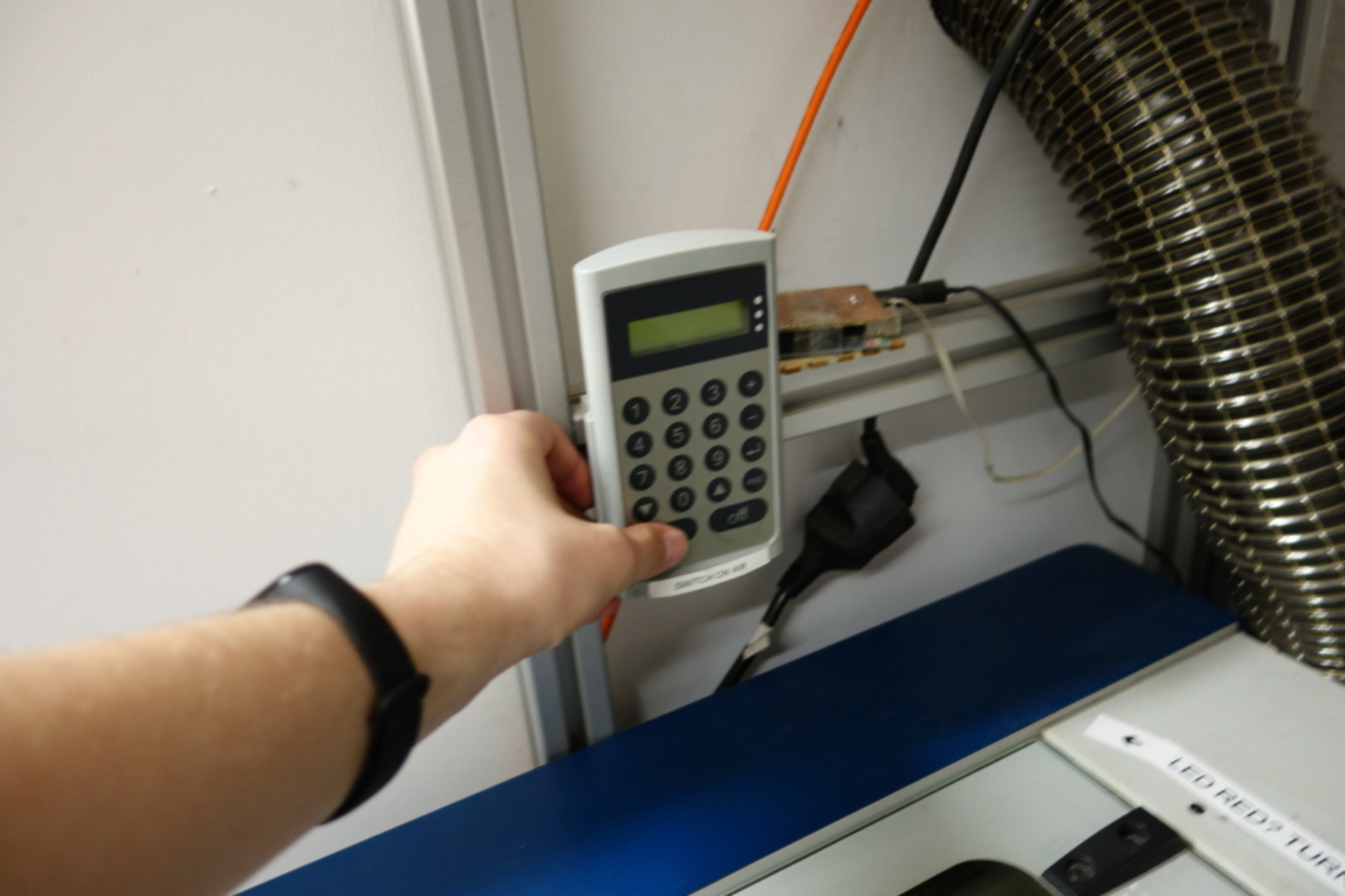
First, we turn on the air filter.
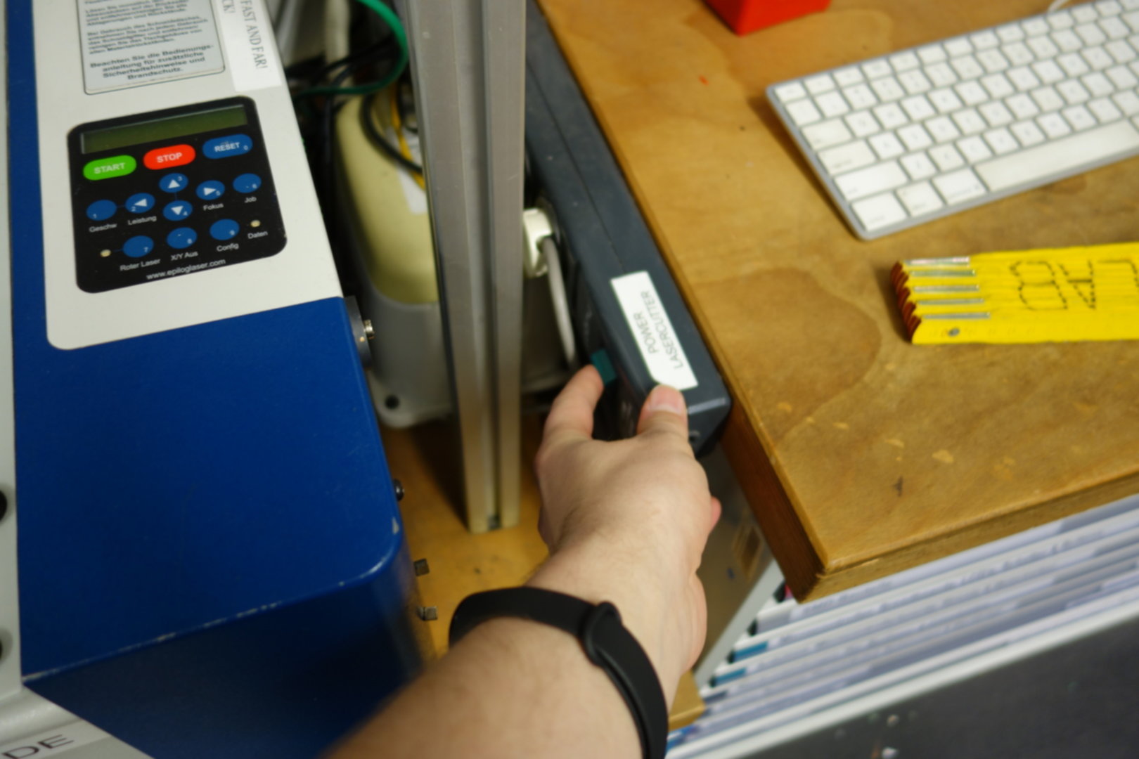
Then, we turn on the laser cutter.
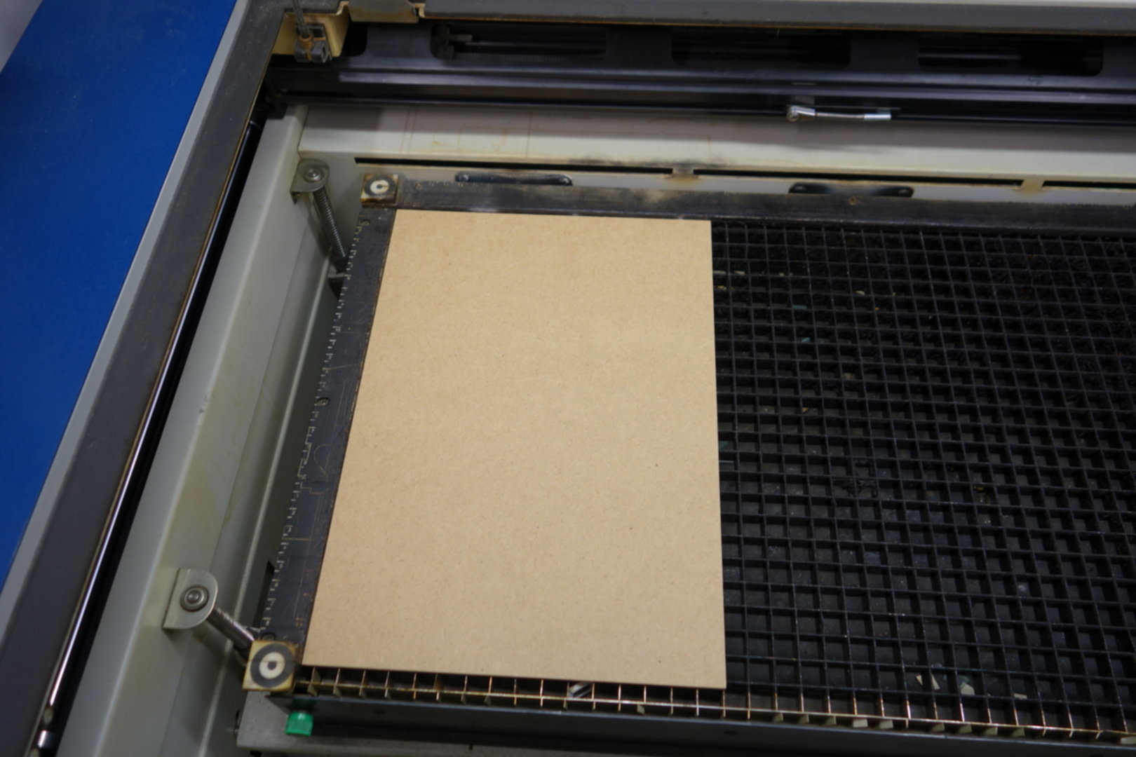
When inserting the material, make sure to align it properly to the edges.
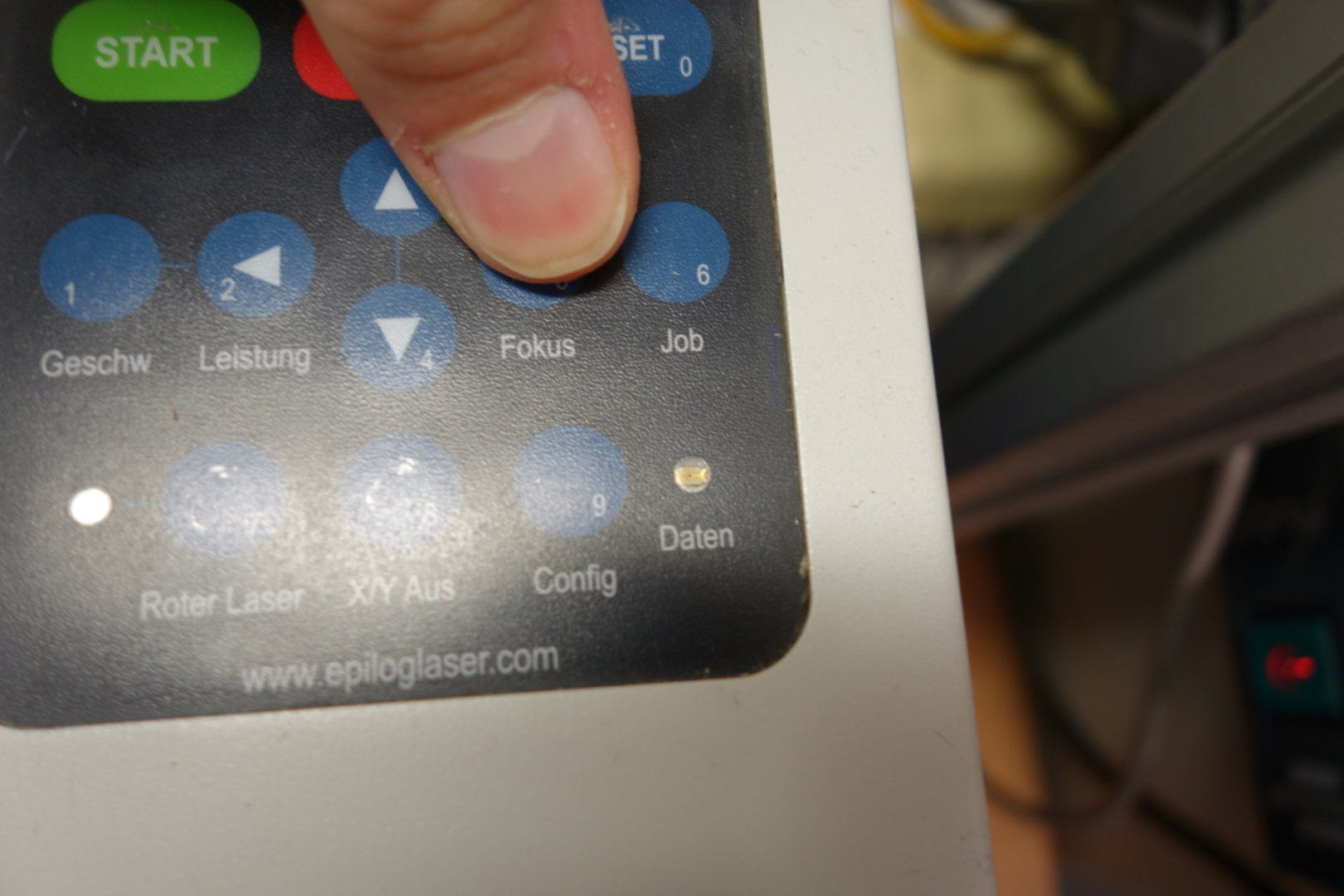
Before starting a job, we have to focus the laser, i.e. adjust it to the material's thickness.
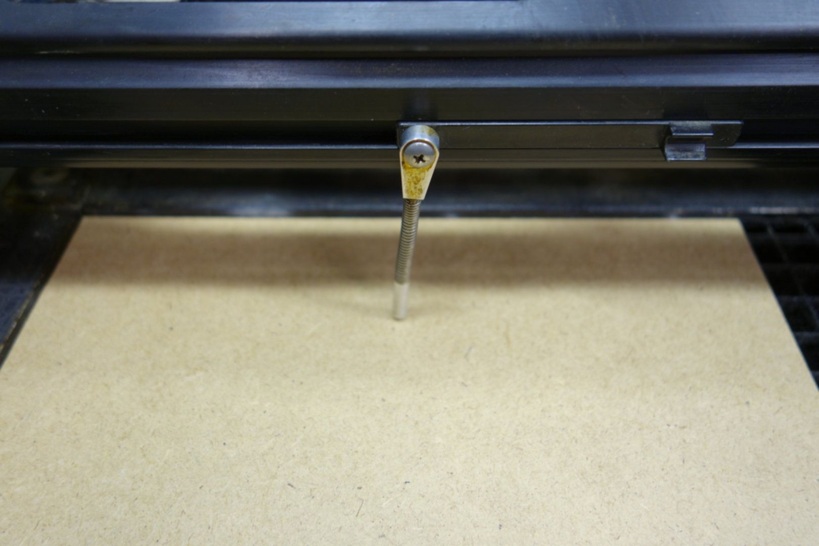
We adjust the height of the laser in a way that the metal pin barely touches the material.
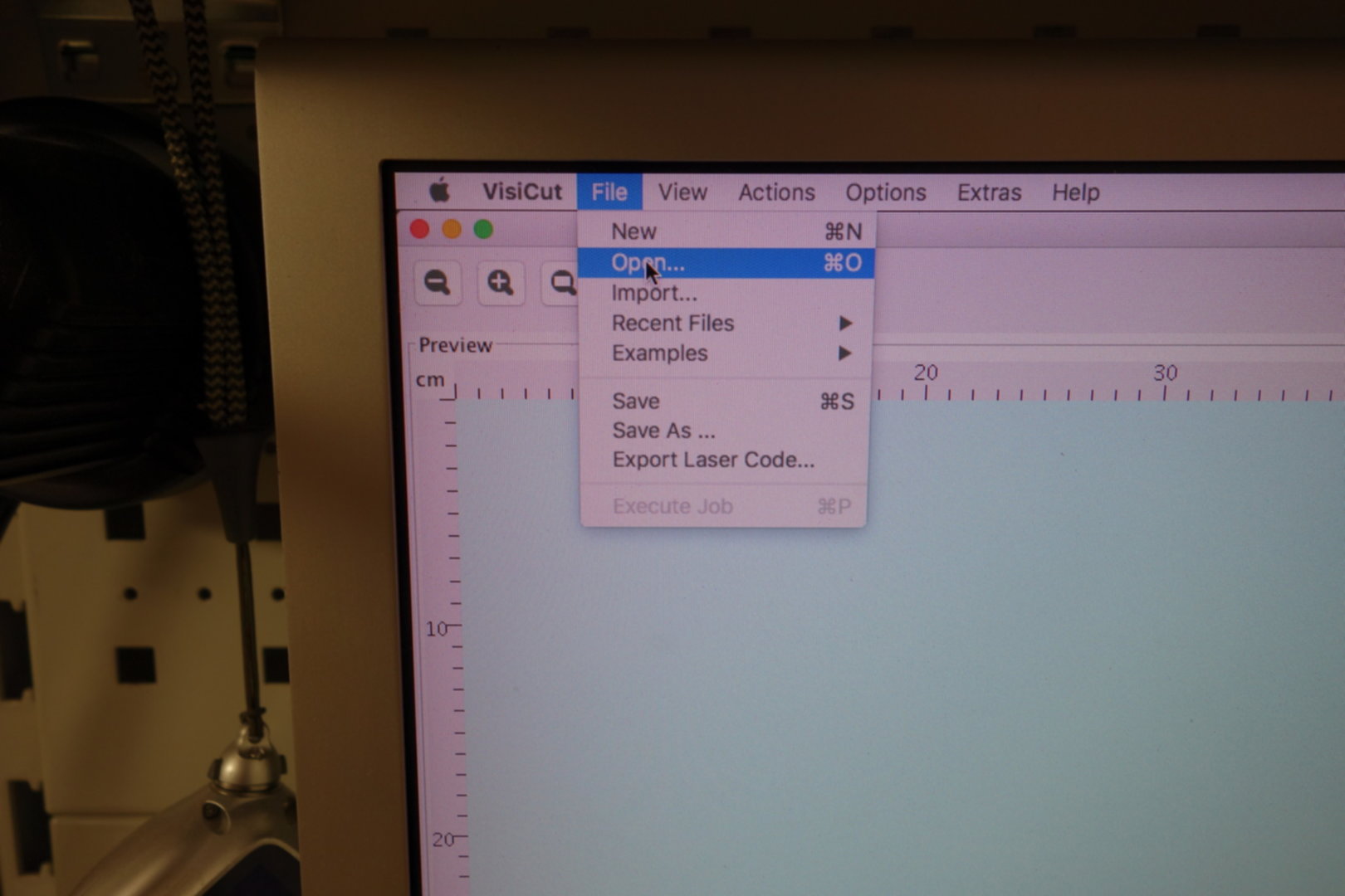
In Visicut, we open the .svg file of our model.
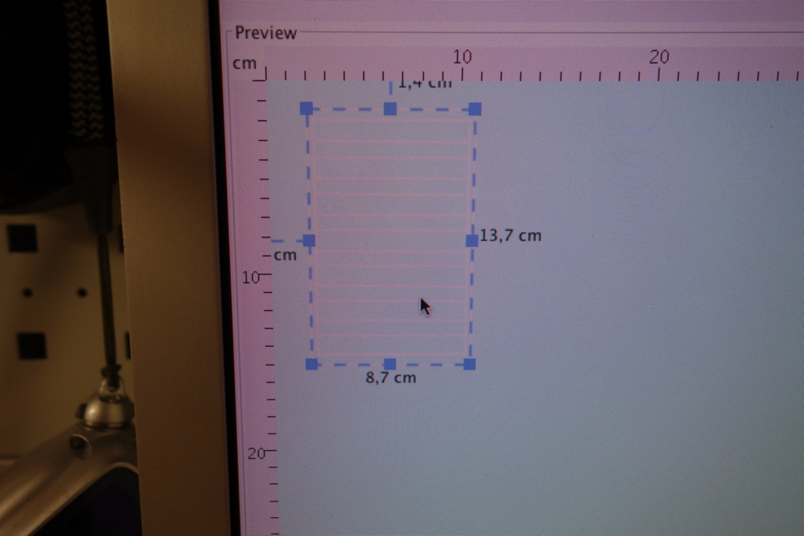
Then we ajust the position and scale to fit on our material.
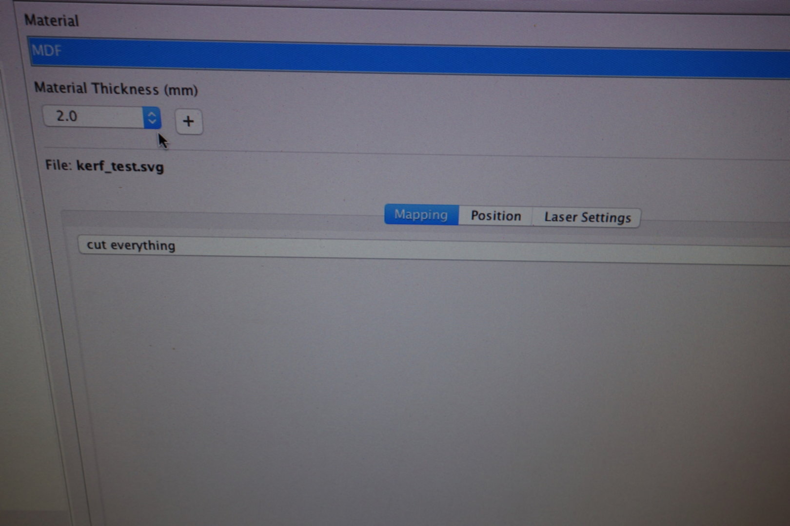
Visicut is able to automatically derive laser speed & power for a given material, thickness, and operation type (for example cutting or engraving).
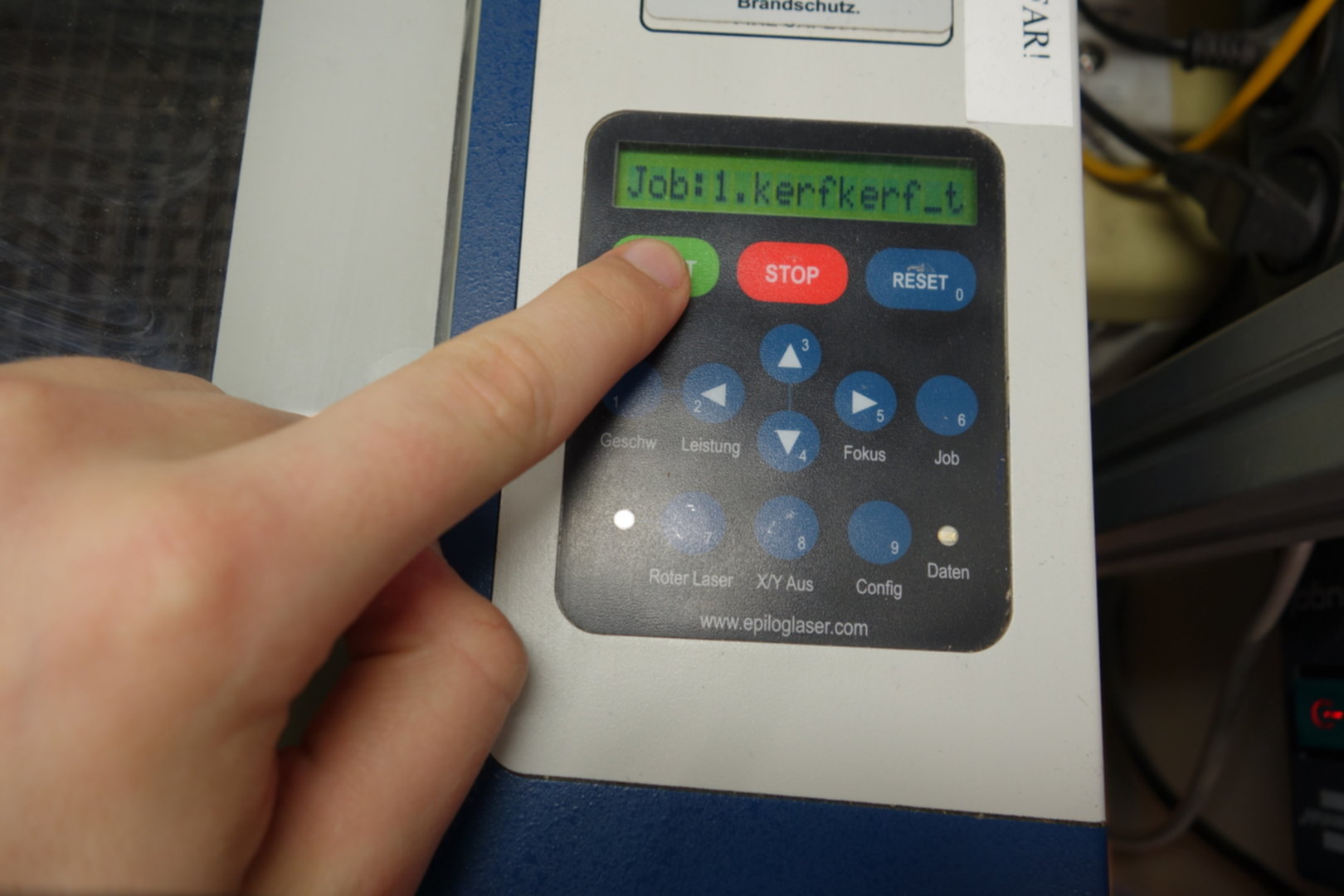
After Visicut transmitted the job to the laser cutter, we have to start it manually.
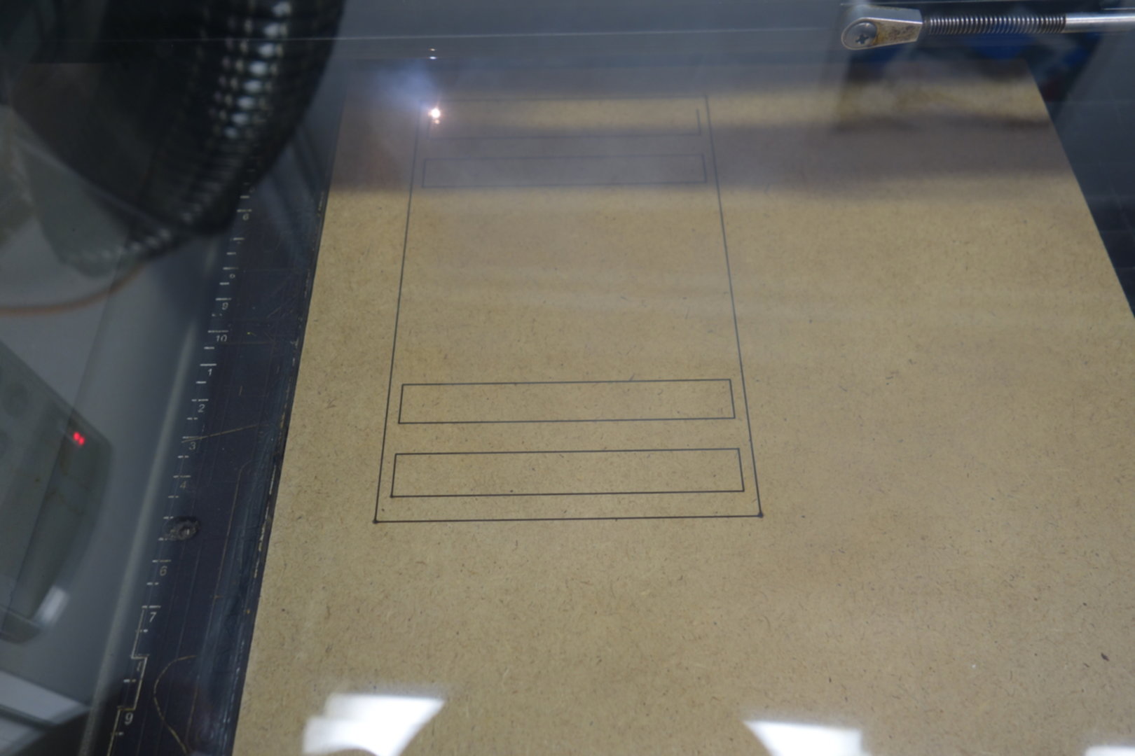
The laser cutter in action.
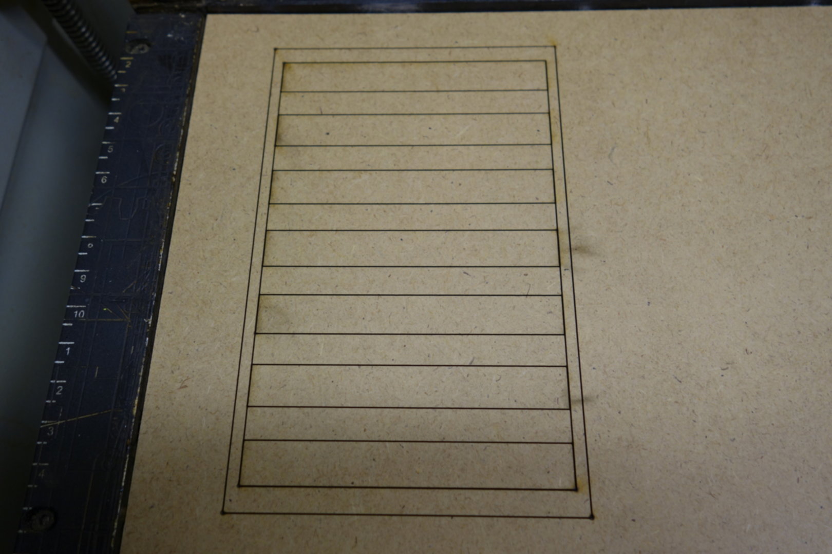
The finished cutout.
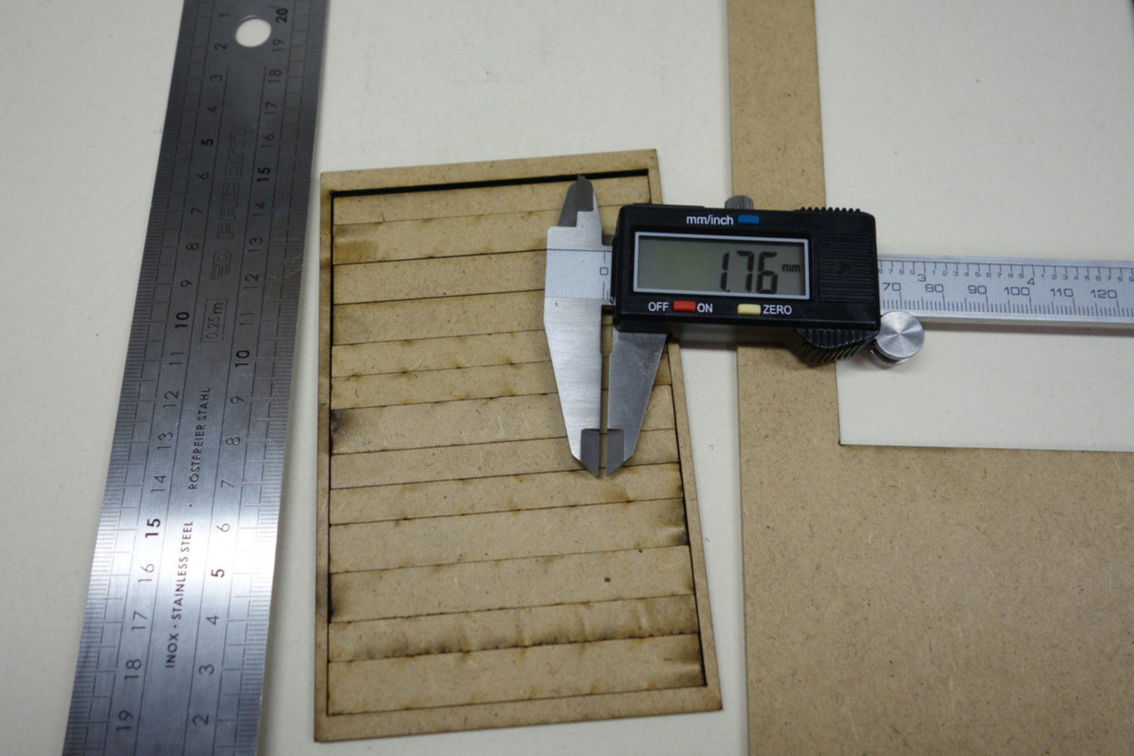
Now, we can shift the cutout bars and measure the resulting gap.
For 14 cuts, we measured a combined gap of 1.76mm, which leads to a kerf of about 0.13mm.
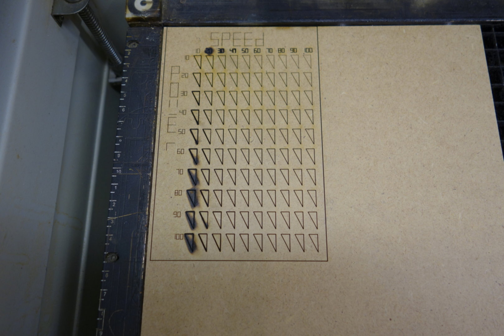
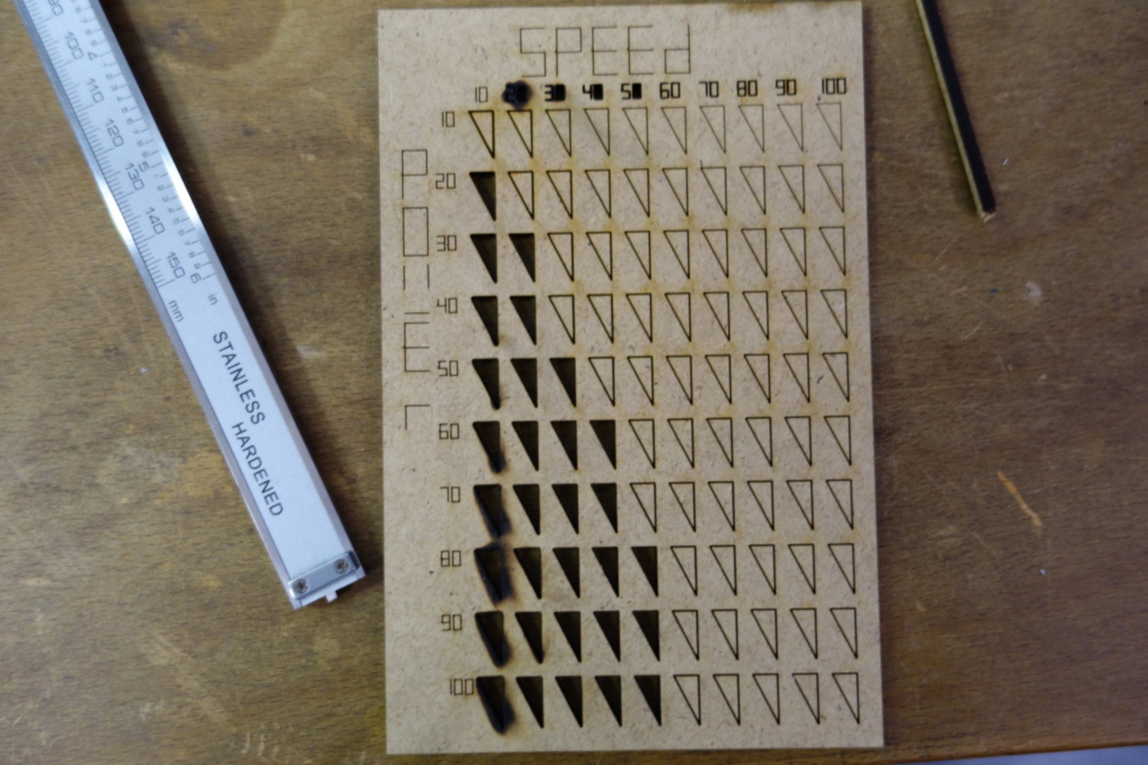
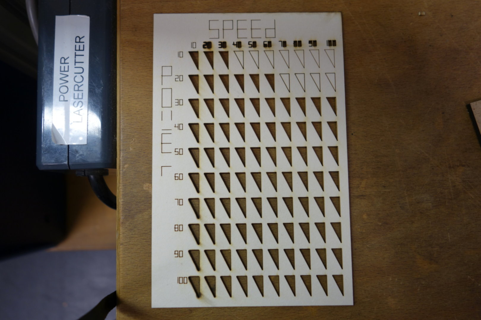
To test the appropriate speed & power settings for a given material, we used a special design.
It depicts a matrix of triangles, covering the range of possible settings for power and speed.
Depending on the values of the parameters and the used material, the laser engraves or cuts the triangles; for
high values of power and low values of speed, burn marks are visible.
We used a script to autoswitch speed and power so we did not need to adjust the for every triangle individually.
This script was made by the fabacademy students of 2018 in our lab.
Click
here for their page.
With this design, it is very fast & easy to determine the right settings for each material.
In the lab, we already have a collection of these boards.
Below, you can compare two boards of different thickness.
