Assignment 12_output devices
01 add an output device to a microcontroller board you've designed and program it to do something
(PROTOTYPE WITH ARDUINO)
For this assignment I want to work with a Servo because I think that could be useful to my final project, using internal servos in the modules to move the less inside.
Just like with the input assignment, I try the code first with an Arduino PCB. I attach the servo to the Digital pin 9 and connect the VCC and GND. The code was very simple to understand but was for understanding how the servo works.

So, the servo move to 0 and the serial monitor write 0, wait 2 seconds, and then move to 180 and the serial monitor write 180. Work perfectly.
MY PCB
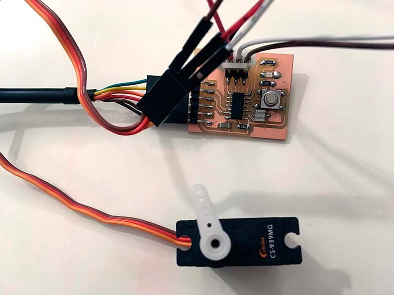
For this assignment I use the board I design for Electronic Design Week, you can check the process of design and fabrication in that week.
Then, just like inputs assignment, I add the serial library and change “Serial” for “mySerial”. I also change the pin of the servo to 5 (PA5 on Attiny44 / 1 or MISO on ISP).

The code was ok, but I have problem loading to the PCB because of use 101% of the space available. I erase the lines where the serial monitor writes 0 or 180, and the code weight 100% so that I could load the PCB.


I re-change the servo to pin 6 because the type of the jumper I was using only allowed me to connect that side of the ISP (GND, MOSI, VCC). So I connect the pin to MOSI-4, that is connected to pin7 of the Attiny44, that in Arduino is the PA6.


The connection wasn`t working very well, so I have to press the connectors in the ISP for the servo could work. And the servo work correctly!

Is a simple example, but help to understand how the outputs and code work. Regarding the size of the code, I have to find out how to reduce its size; probably related to the Arduino libraries.
02 measure the power consumption of an output device
For the final project, I am going to use steppers for my machine, so I seize to fulfil this assignment I haven't done.
I measure the 9V battery before connecting the stepper and the value was 8.7 V without load (the battery has some previous use). I connect the stepper and use it connected to the battery for 20 seconds, the measure while using and was 5.8 V with load.


Then disconnect the stepper and measure again and the value was 7.5 V without load. The stepper consumes a lot of current. If I want to use in the final machine, I have to search for another way to power them.
Because I re-use the board of Electronic Design Week, review my Networking Assignment for more details of design and fabrication of a board whit an output. Check my node boards, where the outputs are the steppers that move the Y and X-axis, and a micro servo that control the Z-axis.

Este obra está bajo una licencia de Creative Commons Reconocimiento-NoComercial-CompartirIgual 4.0 Internacional.