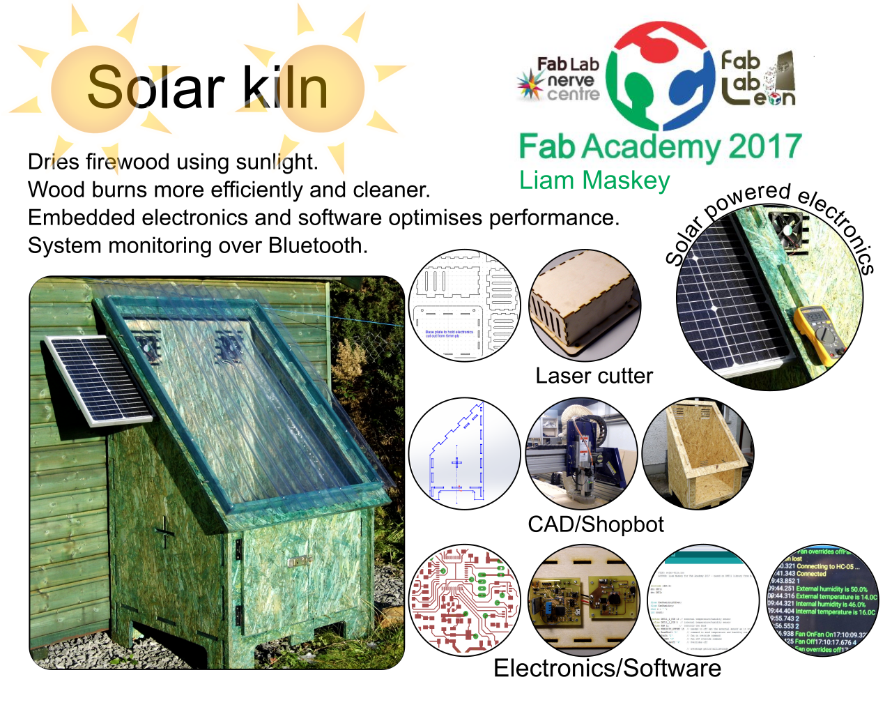
Final Project - Solar Kiln
Presentation
Table of contents
- Introduction
- Description
- Constuction
- Prototyping
- Full size solarkiln enclosure
- Electronics power supply
- Control electronics
- Arduino sketch
- Assembly
- Project timeline
- Downloads
- Links
Introduction
Originally, for my final project, I had intended to build a stove fan based on the Stirling engine, but after some conversations with my instructor it was decided this would not incorporate many of the skills and technologies learnt over the course of the Fab Academy and that a new project was needed. The solar kiln idea came to mind because I intended to do this for the 'Make something big' assignment and it could be easily adapted to include most of the main subject areas of the Fab Academy: Shopbot, laser cutting, 3D CAD, electronics and embedded software
Solar kiln - description
A solar kiln is an external storage compartment that uses sunlight to dry firewood or carpentry wood. Here the solar kiln will be used to dry firewood and will have a number of features to make it more efficient. The links at the bottom of this page give more detail regarding the theory and contruction of typical solar kilns
Wood with lower moisture content gives out more heat as it burns and there is less tar and creosote in the smoke which reduces soot build up in chimneys.
The image below shows a sketch of the solar kiln. The transparent roof works much like a greenhouse where sunlight enters and heats the air and
surrounding wood. Ideally the angle of the kiln roof should match the latitude of the location where the solar kiln is beig sited, which in my case is 54.5 degrees.
However this produces a geometry that has a very tall back and a shallow front . As a compromise I opted to make the roof angle 45 degrees.

The two fans shown in the diagram function to circulate warm air through the wood and out the rear vents. The fans are powered from a photo voltaic (PV) solar panel and controlled via a microprocessor which monitors two temperature/humidity sensors : one inside the solar kiln and one outside. The microprocessor compares internal and external humidity and only turns the fans on when external humidity is less than internal humidity. As the power output of the PV solar panel varies depending on ambinet sunlight the solar kiln electronics will include a method to regulate the power and to that end the kiln will include DCDC conversion using switch mode power supplies.
Construction
The solar kiln will be made of 18mm exterior plywood which will be treated and painted to help preserve it from the elements. The transparent roof section will likely be clear pvc corrugated roofing sheets. Refer to the Applications and Implications assignment for more details regarding the construction.
Prototyping
For the Computer controlled machining assignment I designed a version of my Solar kiln in Soldiworks. This was a 1/3rd scale model which was cut out using the Shopbot. The prototype allowed me to see if the design would fit together; if it was structurally sound; and whether the design was complete. The outcome is the final design will have the interior space divided into two equal partitions allowing wood at different stages of drying to be stored. The divided partition will give added strength to the kiln by joining the front and back sections together. There is also a requirement for two doors on the front to allow dried wood to be easily removed from the kiln. Finally somewhere on the angled face needs to be reserved for the PV solar panel.
Full size solar kiln enclosure
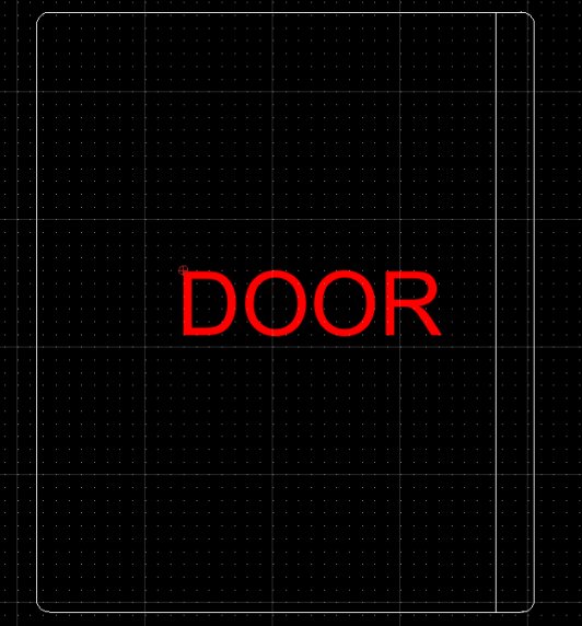
The full size design of the solar kiln enclosure was done in Solidworks with dxf's produced for all the parts to be cut out on the Shopbot. The list of enclosure parts is shown below and the dxf's for them can be downloaded at the end of this page.
- Front section
- Back section
- 2 x sides
- Bottom section
- Top
- Doors
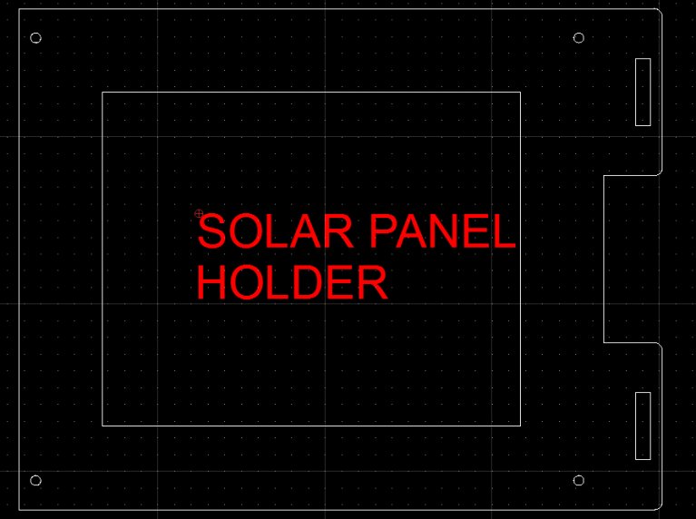
- Solar panel holder
- Roof frame parts
The screen shots below show the various drawings used to produce the Solar Kiln parts on Shopbot
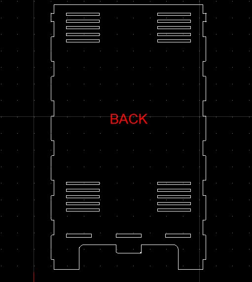
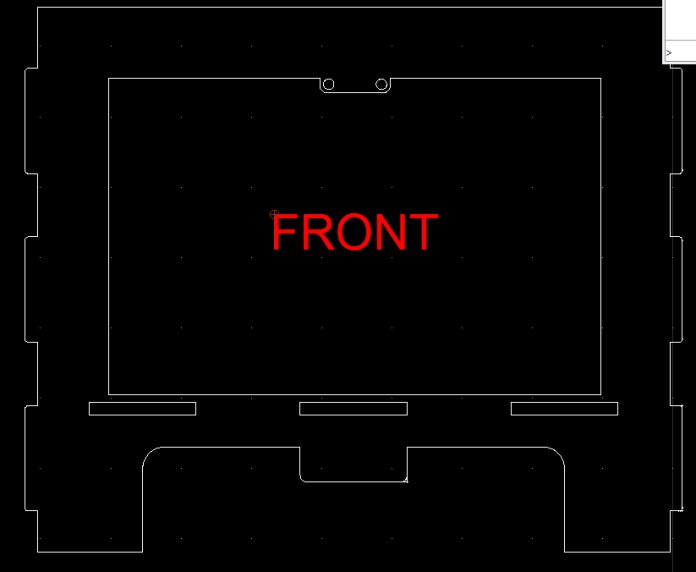
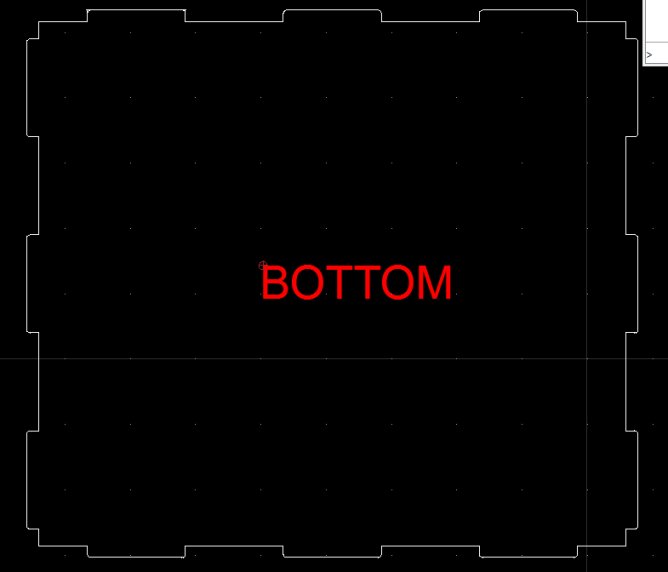
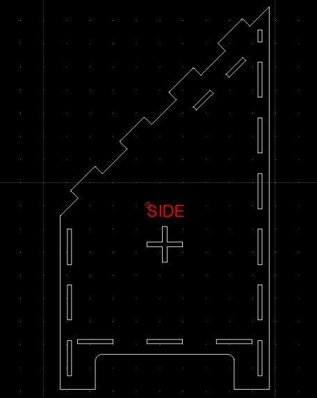
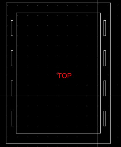
In order to reduce expense 18m OSB panels were chosen as the construction material. The original solar kiln design was to be 1800mm long. Because of the need to have a sharp 45-degree roof angle this meant the back section of the kiln would need to be 1600mm high, giving a final dimension of this part as 1600mm by 1800mm. The maximum panel the Shopbot can cut is 2440mm by 1220mm which means the back section could not be Shopbot cut. For this reason, I decided to reduce the kiln length to 900mm with the option of joining two, or more, solar kilns together.
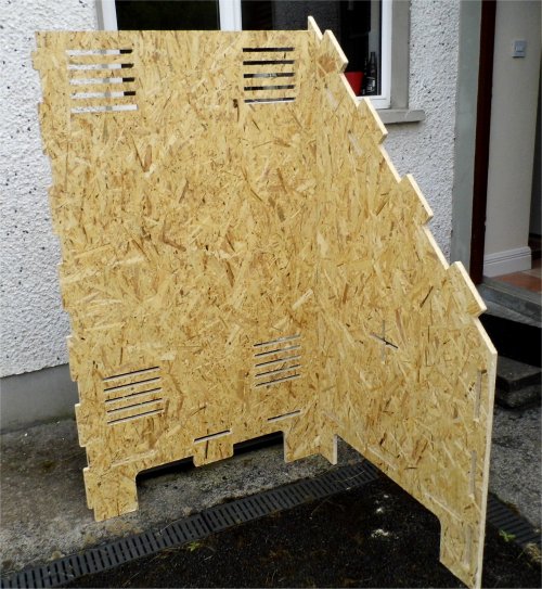
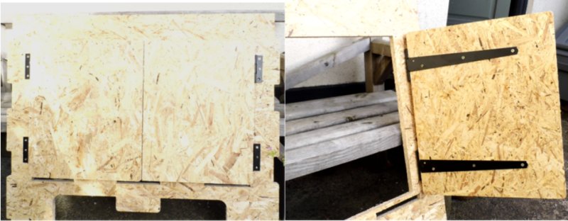
The dxfs were loaded into the Shopbot software tool paths created to cut out the pieces for the solar kiln and then the pieces cut out. Four sheets of 2440x1220x18mm OSB were required. Once cut out the parts were assembled to see if everything fitted together. Scrolling thorough the images below will give a good idea of how everything fits together. The transparent roof was not ready at this stage and the doors still had to have hinges fitted and mounted to the front section.
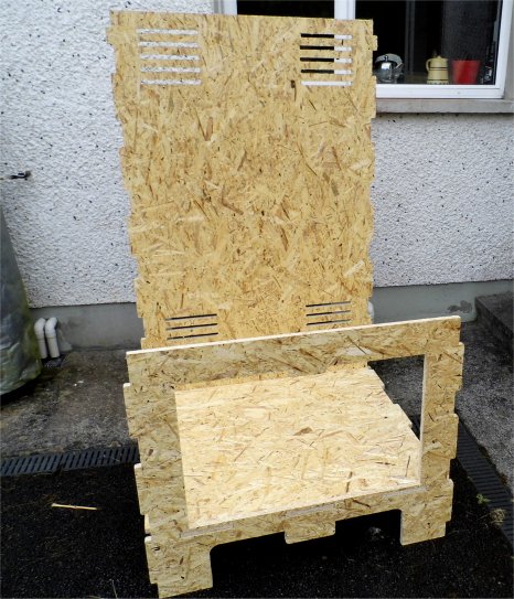
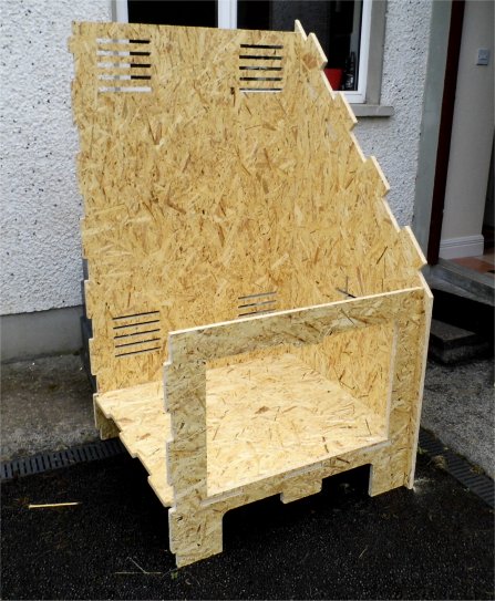
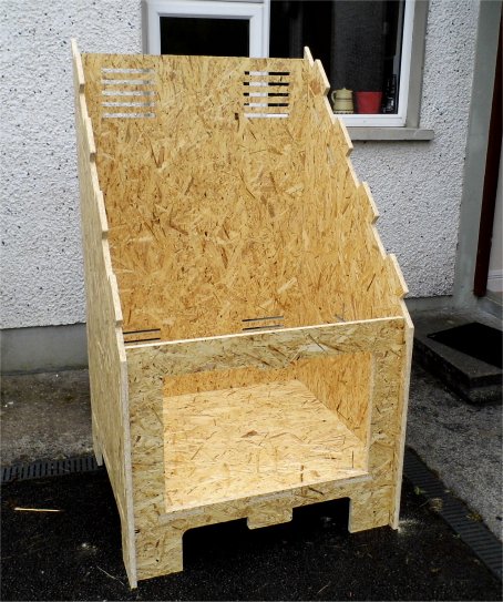
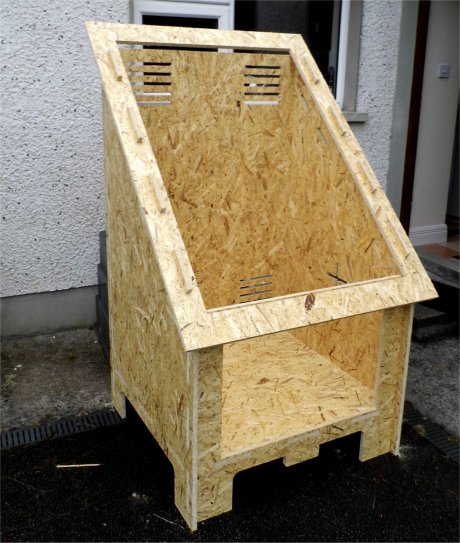
Hinges were fitted to the doors and then these were attached to the front section.
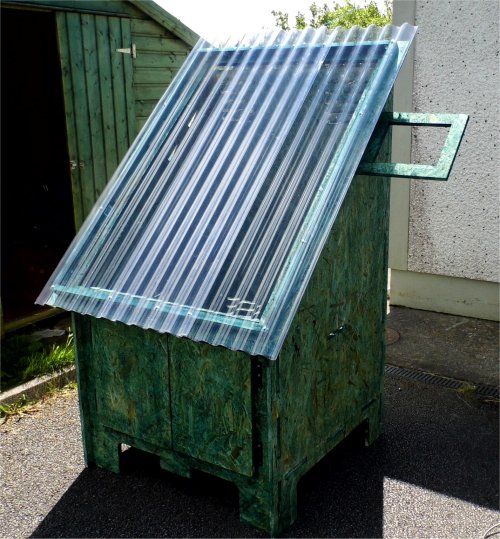
A frame for the transparent roof was made from 25mm by 50mm wooden batten. This was fixed together using small right angle metal brackets. The corrugated PVC roofing was cut to size using tin snips. When I tried cutting it with a jig saw or hand saw the plastic sheet started to break along the cut into pieces.

The solar kiln was taken apart, given a couple of coats of preservative and then reassembled, adding wood glue to the joints to make the construction more secure.
Electronics power supply
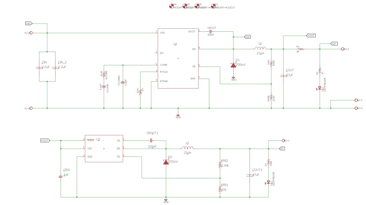
Electrical power for the solar kiln is provided by a small 20W solar panel. Depending on the level of sunlight and electrical load, the solar panel has a wide output voltage, ranging from 14 to 28V. Regulation is needed if this is to supply the 12V for the Solar kiln fans and other electronics. A buck DCDC converter was chosen to provide this regulation. The design of it was done using Webench an online design utility from Texas Instruments.
Webench produced a schematic, pcb layout and bill of materials. However most of the parts chosen by Webench and the pcb layout are not suitable for making a pcb with the Modela MDX-20 so I re-designed the schematic to use larger 1206 parts and laid out a new pcb.
A 5V supply was added to the design in order to power the Microprocessor and lower voltage electronics. Again this was done using Webbench and then editing the schematic to use larger parts so that the pcb can be routed on a Modela MDX-20. The schematic for the Solarkiln power supply is shown below with all the design files available for download.
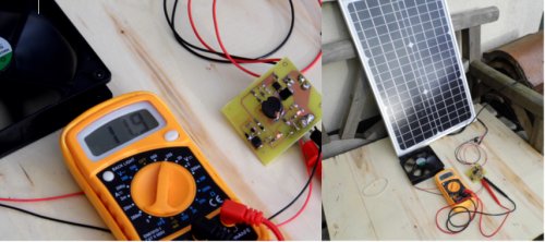
The power supply was assembled and tested to ensure that it could supply both 5V and 12V.
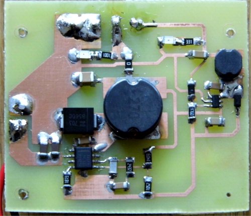
After bench testing the power supply was connected to the solar panel and a 12V 1.8W fan connected to the 12V output. There had to be a reasonable amount of sunlight before enough power could be generated to drive the fan. Both 5V and 12V supplies were present.
Control electronics
The control electronics for the solar kiln makes use of an Arduino compatible microprocessor the ATmega32U4-AU. This processor was chosen because it includes a USB programming interface which removes the need for the USB to serial IC as used in the Arduino UNO and other similar AVR processors. The schematic for the control electronics is shown below.
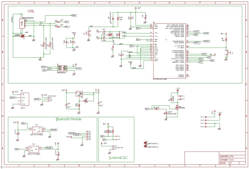
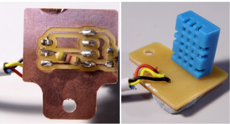
The control electronics features two temperature/humidity sensors, the DHT11, which are connected to input pins of the microprocessor. The DHT11 uses a single digital pin to serial transmit the measured temperature and humidity to a microprocessor as two 16 bit values. One of these sensors is fitted inside the solar kiln and the other fitted outside. The microprocessor compares the humidity of the two sensors and if the humidity outside the solar kiln is less humid than the air inside then the microprocessor will turn the fans on blowing the external air over the stored wood, drying it.
I designed the pcb in Eagle and produced png files so that it could be routed on the Modela MDX-20 but when I tried to route the pcb the trace geometries were too
small and the Modela could not route them properly. I decided to etch out the pcb using FR4 and the process previously described in
assignment 10
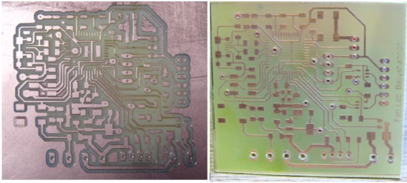
A small board was made for the external humidity sensor to allow it to be mounted. I forgot to include a pull up resistor (4.7K to 10K) to the sensors digital output signal so this was soldered afterwards.
The electronics were assembled and a test Arduino/Leonardo sketch created that would record the results of both humidity sensors and display them in Arduino's serial monitor. The sensors were mounted close together to see how how the sensors temperature and humidity readings agreed. From the serial monitor screen shot the temperature measurements were very close but there was a 4% difference in the humidity measurements. As I have no independent way to measure humidity I can't tell how accurate the humidity sensors are but as the circuit relies on the humidity difference rather than absolute values I decided to make the humidity difference in the application code greater than the difference in measurement accuracy of the two sensors by a wide margin that would accomodate the quoted accuracy of +/-5%..

To allow me to check the Solar Kiln sensors and how the control electronics was functioning I added a Bluetooth Module -HC-05- to the circuit and wrote an Arduino sketch that would monitor the external and internal humidity sensors and turn on the drying fans as appropriate.

The Arduino/Leonardo sketch was downloaded and a mobile phone with a Bluetooth terminal app connected to the control electronics. The commands to monitor and control the solar kiln are listed below and the operation of the communications between the control electronics and a Bluetooth enabled mobile phone are show in image of the phone screen.
| Bluetooth text | Function |
|---|---|
| 1 | Read internal and external sensors |
| 2 | Override to turn fans on |
| 3 | Override to turn fans off |
| 4 | Fan overrides off |

Arduino sketch
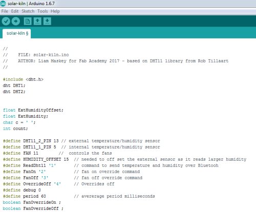
As previously mentioned the ATMEGA32U4-AUR can be configured to behave as an Arduino Leonardo. To do this the Arduino IDE was opened and a USB tiny programmer connected to the programming header on the solar kiln control electronics. Within the IDE, under the Tools menu, the board was selected as Arduino Leonardo and then the Burn Bootloader command selected. This configured the control electronics to appear as an Arduino Leonardo and allowed sketches for the control electronics to be written and programmed using the Arduino IDE.
The sketch interfaces to two DHT11 sensors using an Arduino library provided by Rob Tillaart - available here. The sensors are read approximately once per second and the readings averaged over a period of 60 seconds. If the humidity of the external sensor is lower by a set amount, then the fans are turned on by writing a logic high to the fan control pin. Additional code allows a Bluetooth module to monitor and control the solar kiln electronics.
Assembly
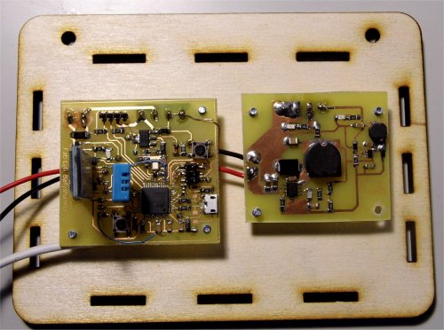
In order to protect the electronics, I made a box for them which was then laser cut. The box base plate was cut from 6mm ply wood and the sides from 3mm ply wood. The electronics were mounted to the base plate prior to assembly into the solar kiln.
The photo voltaic solar panel was fixed to its support panel and mounted on the side of the solar kiln. A voltmeter was connected to the solar panel power connectors and a voltage measurement of 22.3 volts indicated there was be enough power to drive the electronics.

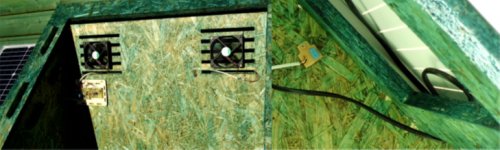
The main electronics was mounted on the inside of the solar kiln and the fans were placed over the rear vents. The solar panel power was connected to the electronics and the fans and external humidity sensor connected to the electronics control and monitoring inputs.
The video below shows the unti operating with everything connected up.
Project timeline
The design of my final project was delayed and it was obvious it would not be completed to an acceptable standard by the presentation dates for Fab Academy 2017. I reorganised the project schedule so I could present it in January 2018, at the start of that year's Fab Academy. The timeline of the Solar Kiln development is outlined below.
- June 2017
- August 2017
- September 2017
- November 2017
- December 2017
- January 2018
Design of enclosure in Solid works and cut out on the Nerve Centre Fab Lab Shopbot.
Assembly of enclosure including roof and doors didn't happen until the start of this month. The enclosure was now out in the open so needed several coats of preservative.
During this month I designed the schematics and pcbs in Eagle, ordered the parts, made the pcbs and assembled the two boards: the power supply board and the control electronics board. The embedded software development was started during this month.
The electronics were tested and a small laser cut enclosure made for them. The embedded software was also developed and tested.
The second half of this month saw the electronics placed in the solar kiln, the fans and solar panel connected and the whole lot tested.
The project is documented and a presentation slide and video is prepared.
The solar kiln project is presented to Neil and the Fab Lab community.
Links
- Accelerated seasoning of firewood. Cornell University Conservation Circular
- Virginia Tech Solar Kiln
Downloads
- Solarkiln drawings
- Solarkiln power supply layout
- Solarkiln control electronics layout
- Solarkiln bill of materials
- DHT11 data sheet
- Solar Kiln Arduino sketch