Computer Controlled Machining
Table of contents
Prototype of final project - solar kiln
For this assignment I decided to make a 1/3rd scale prototype of my final project, a solar kiln, out of 9 mm plywood using the Shopbot.
Test cuts
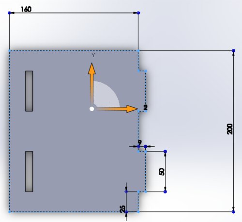
As I am only able to get to the Derry Fab Lab one day per week I decided to use my Stepcraft 420 to generate a test cut. This would give me an idea of how CNC cutting works and allow me to see how accurate the cut out pieces are in relation to the original design. The working area of the Stepcraft 420 is 300 x 420 x 140mm. I drew a test piece in Solidworks which had the dimensions of the two main prototype joints: a 50 mm x 9mm slot and a 50 mm x 9mm finger. The Solidworks design was saved as a dxf which I then imported into Cut2D software. One thing to note, the Solidworks design units have to be in millmetres as Cut2D expects dxf dimensions to be in millimetres. Originally the Solidwork's drawings were in centimetres and the dxfs imported into Cut2D 1/10th of their scale.
Cut2D
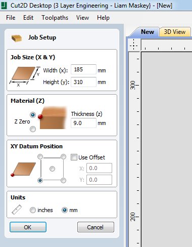
Cut2D comes from the same company, Vectric, that supplies the software for Shopbot so what is written here for Cut2D will apply to Shopbot software. With Cut2D opened I selected File->New and setup the job dimensions to match the size of the piece of plywood that would be cut.
The next step was to import the dxf of the design and this is accomplished by selecting File->Import Vectors and selecting the drawing.
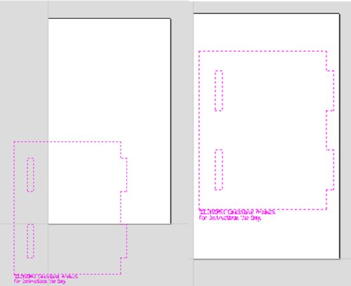
When first loaded the vectors can be offset against the work area. To fix this, under the Transform Objects menu select
Align Selected Object and from the available options chose Align to Material, selecting the option that centres the imported vectors
on the work piece.
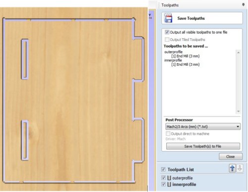
With the vectors imported I first of all selected the outer edge as a profile toolpath and added tabs to it. A 3mm end mill was selected and the routing depth set at 10mm allowing three passes with the mill cutting on the outer edge. Once the parameters for the toolpath had been set the calculate button was pressed and this generated a toolpath.
Next, a toolpath was applied to the inner slots. Again the routing depth was set to 10mm, 3 passes but this time the cut was to happen on the inner edges.
One thing I didn't notice until I had cut two test pieces was that for the outer profile some of the cuts were happening on the inside of the profile with the result that the join fingers were 3mm longer than needed.It was only when I looked closer at the generated toolpath that I observed that some of the paths were placed on the inside of the vectors.
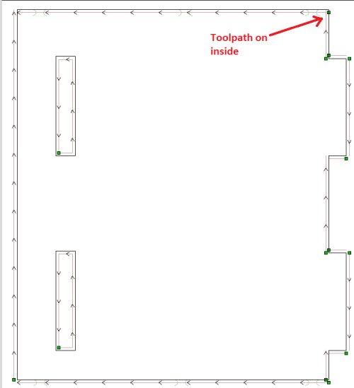
This can be fixed by selecting individual vectors and choosing the cut inside or outside options to suit and I will do this when cutting out the prototype, but for the test cuts this mistake was present.
Once the paths had been calculated they were saved to a file in the Mach 2/3 Arcs format.
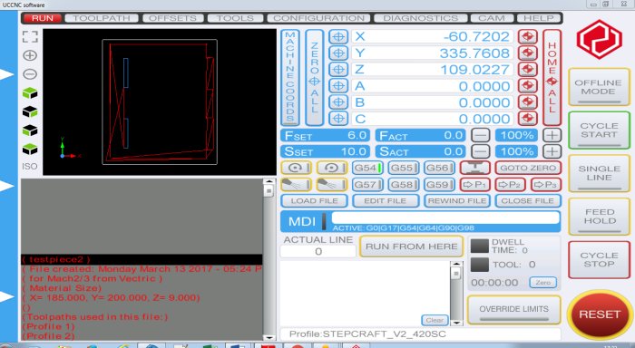
The software used to control the Stepcraft is from UCCNC. The screenshot below shows the test piece file loaded into the software.
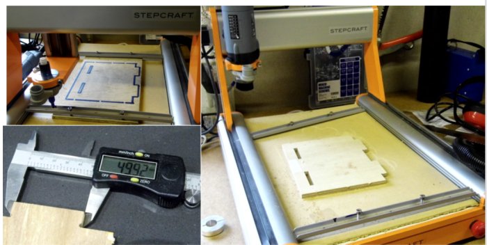
Before millling the test cut I placed a pen in the holder for the router and ran the Stepcraft so that it drew the test cut. Once I was satisfied
everything was ok I installed the router and cut out the test piece. I measured the cut outs and found that the finger was 49.92mm while the cut
out width was 8.7mm and the length 49.6mm.
Solar kiln design
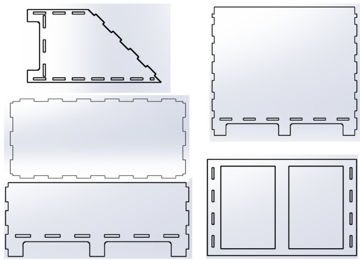
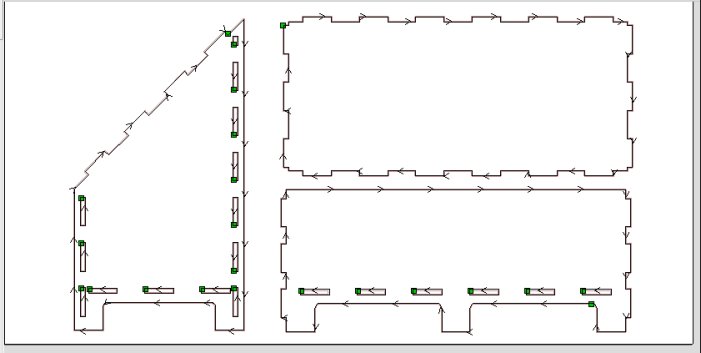
I decided to use Solidworks to design the solar kiln. Previously I had used Librecad to produce some prototype drawings and may go back to that software when my Solidworks license expires, however after an initial steep learning curve I found Solidworks intuitive, at least for the uncomplicated design here. The image below shows the main components of the solar kiln. Once the designs had been finalised they were saved as dxfs.
Shotbot
The Shopbot software PartWorks 3.0 was started and the work piece dimensions set to 1220 x 607 x 9mm as this was the size of the plywood sheets available. A number of dxfs were loaded and placed on the application working area. A 6mm compression bit was aready in the Shopbot and it was decided to used this for cutting. The machine vectors were set to cut on the Outside/Right and with this settng, the software automatically calculated the correct tool paths to cut the fingers on the outside and the slots on the inside. Also the job was set up to cut on one pass with a depth of 10mm. The Shopbot spindle speed and feed rate wer set at the following values:
- Spindle speed: 18000 rpm
- Feed rate: 100mm/s
Once the toolpaths had been calculated the toolpath file was saved in the correct Shopbot file format. This procedure was done for all the pieces to be cut. These files are available for download at the bottom of this page.
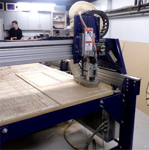
The plywood sheet was screwed to the Shopbot bed and the control software opened. The spindle was moved to the right hand corner of the work piece and zeroed in the software for X and Y. Next the spindle was moved to the centre of the work piece and the Z direction zero plate was used to zero the Z position. The spindle was then sent to the X and Y zero position, the toolpath file loaded and the command to begin cutting sent to the Shopbot. The following image shows the Shopbot cutting out the first set of parts.
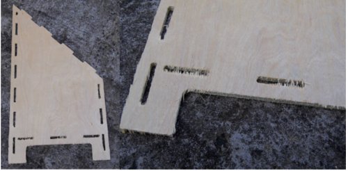
After the first set was cut it was obvious that the cut depth of 10mm wasn't deep enough as some of the parts were still connected to the main pywood sheet with slivers of uncut wood. I modified the toolpath to cut at 10.5mm and ran the cut again. This was a little bit better and the parts came off the plywood but I made the next set of toolpaths cut deeper at 11mm. However I found that this was still not satisfactory and now conclude that the Z zero position wasn't set properly because the plywood sheets were warped and when the zero was taken it was on a higher part of the warp with the result that some parts of the wood remained uncut or the underside of the cut was left rough.
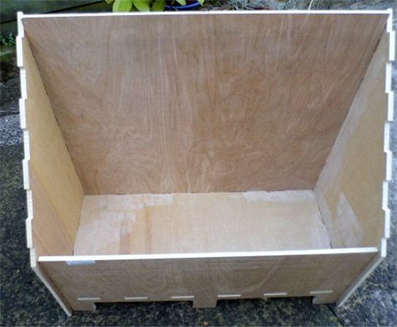
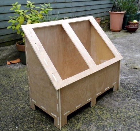
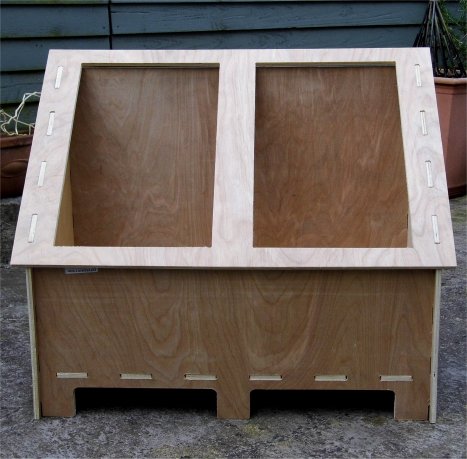
Completed prototype
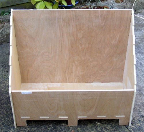
The images below show the assembled prototype. Because the Z position hadn't been setup properly there was some sanding and finishing required on the final parts to allow them to fit together. There was also a problem with the back of the solar kiln as it interfered with the top piece: that is the height of the back piece needed reduced. The prototype also showed that some supporting pieces need included in the design to increase strength and rigidity. Finally, the joints are too tight and they needed some sanding to get then to mate with the slots.
Conclusions
The lessons learned from using the Shopbot were:
- Take care to zero the Z position and do it at the lowest point of the plywood sheet.
- Do test cuts with the wood and bit that is going to be used, and feed this information back into the design parameters.
- The joints seemed okay but perhaps taper or round the corners to make for an easier fit.
- Further design needed on the solar kiln to make it more robust and useful.
- Wood is expensive!