

Assignment :
Group Assignment : Experiment with other architectures
Individual Assignment : Read a Microcontroller data sheet
program your board to do something, with as many different programming languages and programming environments as possible
If a hardware is the body of a person then the program running on it is his soul. So it is so much important that to program someone's soul with so much patience so that it won't destroy his physical existence.Hardware programing is an art of integrating life into inorganic materials . I have been so much facinated about computer science since my early ages.So I consider this as interesting oppurtunity to understand the inner workings of a microcontroller . I have previous experience in arduino programing and a little experience in avr c .We learned basic structure of assembly programming in college so I also wanted to test some assembly coding in attiny 44
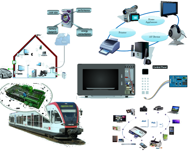
A microcontroller (or MCU for microcontroller unit) is a small computer on a single integrated circuit. In modern terminology, it is similar to, but less sophisticated than, a system on a chip or SoC; an SoC may include a microcontroller as one of its components. A microcontroller contains one or more CPUs (processor cores) along with memory and programmable input/output peripherals. Program memory in the form of ferroelectric RAM, NOR flash or OTP ROM is also often included on chip, as well as a small amount of RAM. Microcontrollers are designed for embedded applications, in contrast to the microprocessors used in personal computers or other general purpose applications consisting of various discrete chips like ADC(analog to digital converter),DAC [Digital-to-Analog Converter] etc.[wiki].
These devices are in every were. We can see embedded systems in your car ,TV, Refrigerator,Phone etc
AVR is a family of microcontrollers developed by Atmel beginning in 1996. These are modified Harvard architecture 8-bit RISC single-chip microcontrollers. AVR was one of the first microcontroller families to use on-chip flash memory for program storage, as opposed to one-time programmable ROM, EPROM, or EEPROM used by other microcontrollers at the time. AVR microcontrollers find many applications as embedded systems; they are also used in the Arduino line of open source board designs.
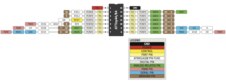
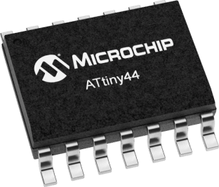
The ATtiny44 is a high-performance, low-power Microchip AVR RISC-based CMOS 8-bit microcontroller.It combines 4KB ISP flash memory, 256-Byte EEPROM, 256B SRAM, 12 general purpose I/O lines .The ATtiny44 consistof 32 general purpose working registers, an 8-bit timer/counter with two PWM channels, a 16-bit timer/counter with two PWM channels, internal and external interrupts, an 8-channel 10-bit A/D converter and a programmable gain stage (1x, 20x) for 12 differential ADC channel pairs. It has a programmable watchdog timer with internal oscillator.The a internal calibrated oscillator and three software selectable power saving modes makes it suitable for small embedded products . By executing powerful instructions in a single clock cycle the device achieves throughputs approaching 1 MIPS per MHz .It also balance power consumption and improve processing speed.
If you want to know more about ATtiny44 just go through the datasheet
These are some basic details about the chip.
| Parameter Name | Value |
|---|---|
| Program Memory Type | Flash |
| Program Memory (KB) | 4 |
| CPU Speed (MIPS) | 20 |
| RAM Bytes | 256 |
| Data EEPROM (bytes) | 256 |
| Digital Communication Peripherals | 1-SPI, 1-I2C |
| Capture/Compare/PWM | 1 Input Capture, 1 CCP, 4PWM |
| Timers | 1 x 8-bit, 1 x 16-bit |
| Comparators | 1 |
| Temperature Range (C) | -40 to 85 |
| Operating Voltage Range (V) | 1.8 to 5.5 |
| Pin Count | 14 |

Arduino is an open source computer hardware and software company, project, and user community that designs and manufactures single-board microcontrollers and microcontroller kits for building digital devices and interactive objects that can sense and control objects in the physical and digital world.[wiki]
Since i have some basics in arduino i decided to try arduino first .
Since the original Arduino software doesnot support the ATtiny44. I have to add some Board directorys for adding my ATtiny44 board to my arduino enviournment
open File -> Preferences
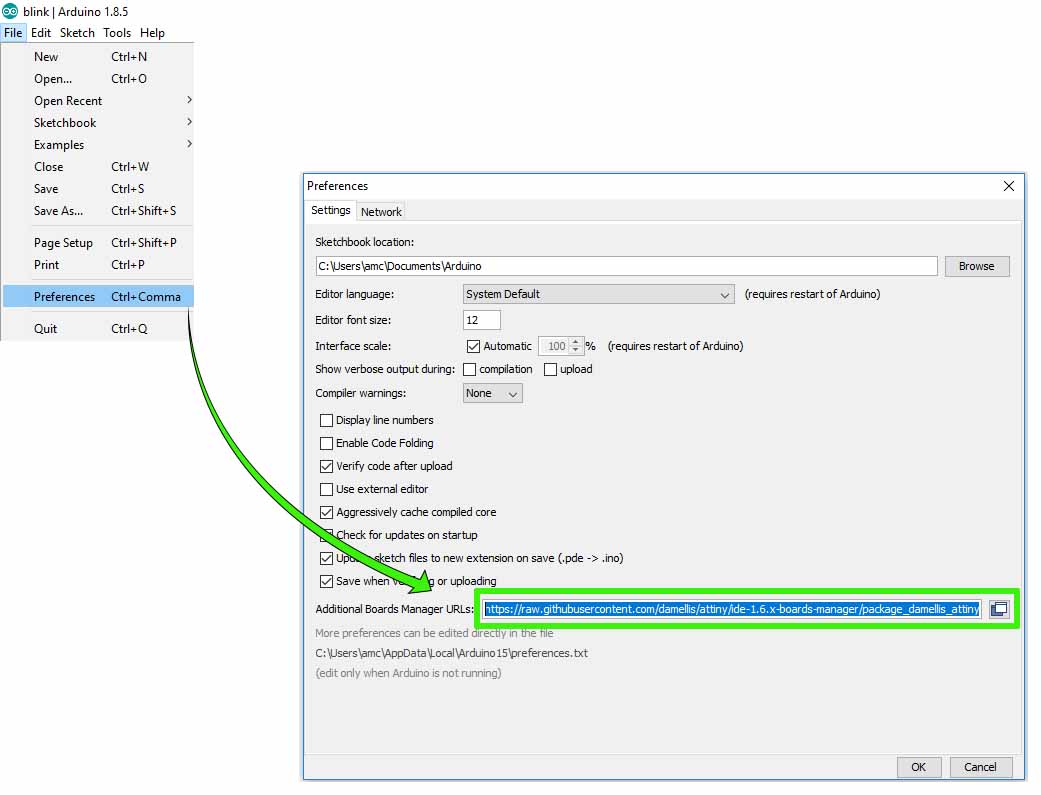
Copy and paste the below URL in the Additional Boards Manager URLs field.
Open Tools -> Board -> Board Manager
Search for attiny and click to install the board file.
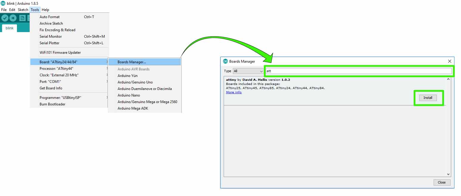
further, We need to install the operating system driver for our USBTinyISP.I usde a driver developed by Adafruit you can download that Here
So next we have to code our board in arduino .
Here is the ATTiny44 to Arduino PIN map
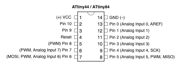
ATTiny44 PINs
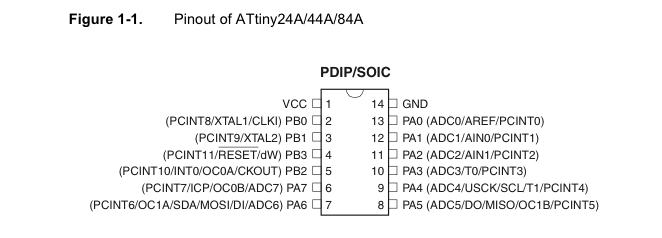
This is the schmatic of my PCB. we have to refer our schmatic befor coding our board.
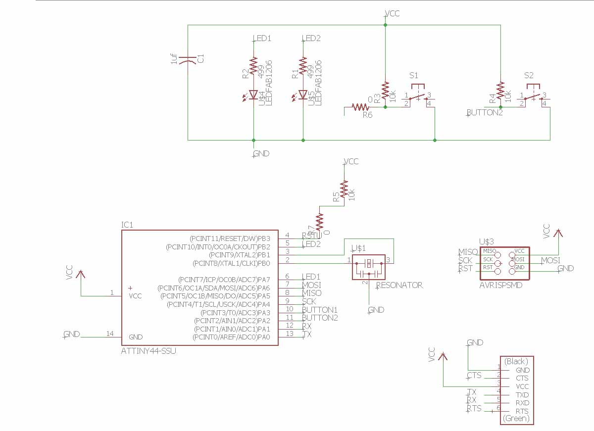
We are using the USBtiny programmer we made during the Week 5 assignment for programming our board. The ISP Programming of ATtiny 44 using six pins .These are the 6 pins.
#define LEDL 8
#define LEDR 7

#define SWL 3
#define SWR 2

void setup() {
  pinMode(LEDL , OUTPUT);
  pinMode(LEDR , OUTPUT);
  pinMode(SWR , INPUT);
  pinMode(SWL , INPUT);
}
void loop() {
  digitalWrite(LEDL, HIGH);
  digitalWrite(LEDR, HIGH);
  delay(1000);
  digitalWrite(LEDL, LOW);
  digitalWrite(LEDR, LOW);
  delay(1000);
}
Befor uploading the program to our board.We have to tell our IDE some more things.
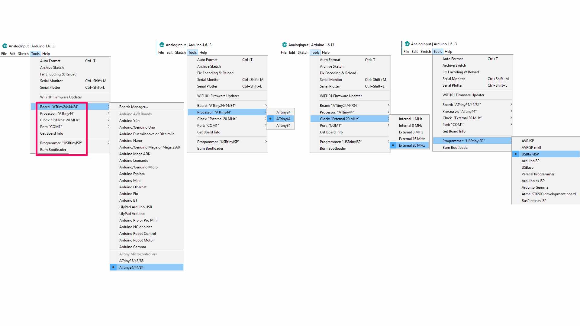
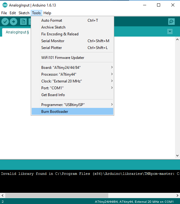
Remark! ATTiny44 is defaultly set to use the Internal clock .So if you are using Arduino to program it. It will not get program initially . We have to upload the Bootloader first.
#define LEDL 8
#define LEDR 7

#define SWL 3
#define SWR 2

void setup() {
  pinMode(LEDL , OUTPUT);
  pinMode(LEDR , OUTPUT);
  pinMode(SWR , INPUT);
  pinMode(SWL , INPUT);
}
void loop() {
  if (digitalRead(SWR) == 1) {
    digitalWrite(LEDL, HIGH);
    digitalWrite(LEDR, HIGH);
  }
  else {
    digitalWrite(LEDL, LOW);
    digitalWrite(LEDR, LOW);
  }
}
Studio 7 is the integrated development platform (IDP) for developing and debugging all AVR® and SAM microcontroller applications. The Atmel Studio 7 IDP gives you a seamless and easy-to-use environment to write, build and debug your applications written in C/C++ or assembly code. It also connects seamlessly to the debuggers, programmers and development kits that support AVR® and SAM devices.
Additionally, Studio includes Atmel Gallery, an online app store that allows you to extend your development environment with plug-ins developed by Microchip as well as third-party tool and embedded software vendors. Studio 7 can also seamlessly import your Arduino sketches as C++ projects, providing a simple transition path from Makerspace to Marketplace.
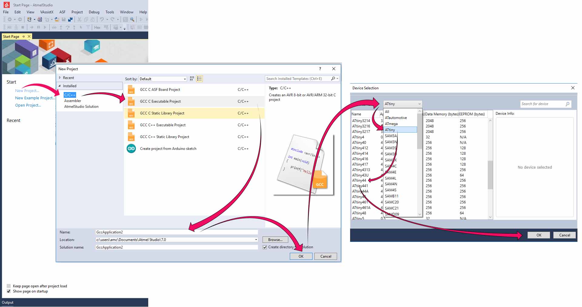
To start a new project .Just open the software and choose new project .Select Gcc C Executable Project .Then select a name and click Ok .Select Our Chicp from the next window and click on the okey button.Now the enviournment is created
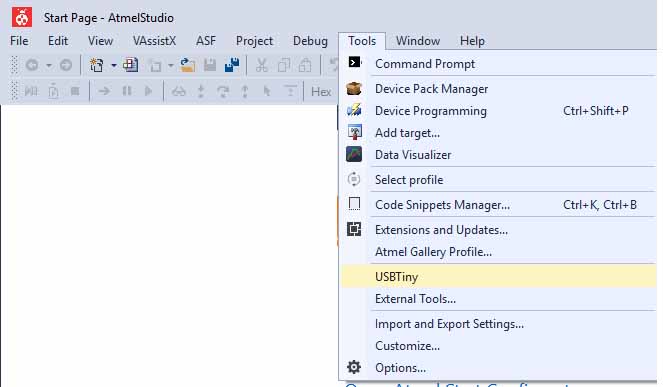
Next we have to add our programmer to our enviournment. Choose Tools -> External Tools -> Fill the spaces as shown below. Put this
-c usbtiny sp -p t44 -F -v -U flash:w:$(TargetDir)$(TargetName).hex:i in the argument space
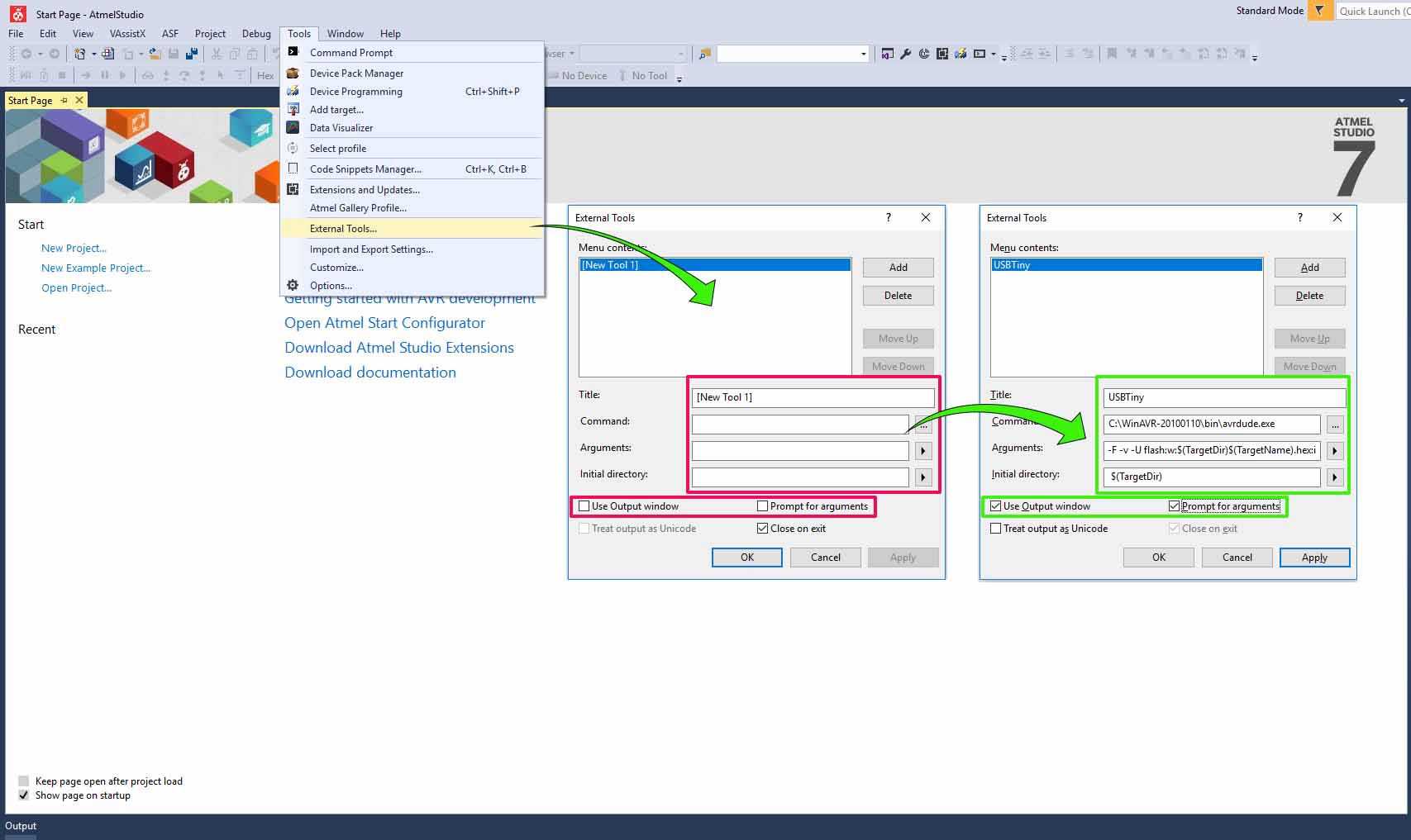
Check wether the programmer is properly configured.Open tools and check wether our programmer is added.Just test it by uploading a simple code.
I tried a simple code to blink the LEDs in my board
Before starting the programming a little bit about the programming.
DDRx DDR stands for Data direction Register, basically it is an 8-bit register which determines whether one pin will be an input or output pin. If you want the pin you connected the LED to be set as output then you should give that value of that as 1 on DDRx. Example I connected my LED to PA7, hence I have to make it as out put in DDRA.Hence I give the code to set the pin PA7 as out put by writing. DDRA=0xff; This is HEX equivalent for DDRA=ob11111111 What this does is that it will set all the pins on the PA7 as output pins.
PORTx while DDRx denotes the direction of the Pin, PORT denotes the state of it. That means if I give a value 1 in the PORT register of that pin It would be set to HIGH, or 5V in case of the micro controller.
PINx register is a dynamic register whose value will be automatically updated based on the received values of the sate of all pins, so 5V to that pin will write 1 to that register.
Now lets start programming .To build the code just click build -> Build Solution or press "F7"

#include <avr/io.h> // AVR input/output library
#define F_CPU 20000000 // Since we connected a 20MHz crystal into the circuit
#include <util/delay.h> // Delay library
main()
{
DDRA=(1<<7); //set pins 7 in the A port as output pins.
DDRB=(1<<2); //set pins 2 in the B port as output pins.
while(1) // infinte loop
{
PORTA|=(1<<7); //Turns pin7 ON.
PORTB|=(1<<2); //Turns pin7 ON.
_delay_ms(1000); //wait for one second.
PORTA&=(!(1<<7)); //Turns pin7 OFF.
PORTB&=(!(1<<2)); //Turns pin7 OFF.
_delay_ms(1000); //wait for one second.
}
}
This is the console result.If something wrong will happen It will be displayed here.
------ Build started: Project: GccApplication7, Configuration: Debug AVR ------
Build started.
Project "GccApplication7.cproj" (default targets):
Target "PreBuildEvent" skipped, due to false condition; ('$(PreBuildEvent)'!='') was evaluated as (''!='').
Target "CoreBuild" in file "C:\Program Files (x86)\Atmel\Studio\7.0\Vs\Compiler.targets" from project "c:\users\amc\Documents\Atmel Studio\7.0\GccApplication7\GccApplication7\GccApplication7.cproj" (target "Build" depends on it):
Task "RunCompilerTask"
Shell Utils Path C:\Program Files (x86)\Atmel\Studio\7.0\shellUtils
C:\Program Files (x86)\Atmel\Studio\7.0\shellUtils\make.exe all --jobs 4 --output-sync
make: Nothing to be done for 'all'.
Done executing task "RunCompilerTask".
Task "RunOutputFileVerifyTask"
Program Memory Usage : 114 bytes 2.8 % Full
Data Memory Usage : 0 bytes 0.0 % Full
Done executing task "RunOutputFileVerifyTask".
Done building target "CoreBuild" in project "GccApplication7.cproj".
Target "PostBuildEvent" skipped, due to false condition; ('$(PostBuildEvent)' != '') was evaluated as ('' != '').
Target "Build" in file "C:\Program Files (x86)\Atmel\Studio\7.0\Vs\Avr.common.targets" from project "c:\users\amc\Documents\Atmel Studio\7.0\GccApplication7\GccApplication7\GccApplication7.cproj" (entry point):
Done building target "Build" in project "GccApplication7.cproj".
Done building project "GccApplication7.cproj".
Build succeeded.
========== Build: 1 succeeded or up-to-date, 0 failed, 0 skipped ==========
Upload to the Chip using the programmer .Choose Tools -> USBTiny -> OK

This is the Console output.Fortunately everything happend perfectly.
avrdude.exe: Version 5.10, compiled on Jan 19 2010 at 10:45:23
Copyright (c) 2000-2005 Brian Dean, http://www.bdmicro.com/
Copyright (c) 2007-2009 Joerg Wunsch
System wide configuration file is "C:\WinAVR-20100110\bin\avrdude.conf"
Using Port : lpt1
Using Programmer : usbtiny
AVR Part : ATtiny44
Chip Erase delay : 4500 us
PAGEL : P00
BS2 : P00
RESET disposition : possible i/o
RETRY pulse : SCK
serial program mode : yes
parallel program mode : yes
Timeout : 200
StabDelay : 100
CmdexeDelay : 25
SyncLoops : 32
ByteDelay : 0
PollIndex : 3
PollValue : 0x53
Memory Detail :
Block Poll Page Polled
Memory Type Mode Delay Size Indx Paged Size Size #Pages MinW MaxW ReadBack
----------- ---- ----- ----- ---- ------ ------ ---- ------ ----- ----- ---------
eeprom 65 6 4 0 no 256 4 0 4000 4500 0xff 0xff
flash 65 6 32 0 yes 4096 64 64 4500 4500 0xff 0xff
signature 0 0 0 0 no 3 0 0 0 0 0x00 0x00
lock 0 0 0 0 no 1 0 0 9000 9000 0x00 0x00
lfuse 0 0 0 0 no 1 0 0 9000 9000 0x00 0x00
hfuse 0 0 0 0 no 1 0 0 9000 9000 0x00 0x00
efuse 0 0 0 0 no 1 0 0 9000 9000 0x00 0x00
calibration 0 0 0 0 no 1 0 0 0 0 0x00 0x00
Programmer Type : USBtiny
Description : USBtiny simple USB programmer, http://www.ladyada.net/make/usbtinyisp/
avrdude.exe: programmer operation not supported
avrdude.exe: Using SCK period of 10 usec
avrdude.exe: AVR device initialized and ready to accept instructions
Reading | ################################################## | 100% 0.01s
avrdude.exe: Device signature = 0x1e9207
avrdude.exe: safemode: lfuse reads as FE
avrdude.exe: safemode: hfuse reads as DF
avrdude.exe: safemode: efuse reads as FF
avrdude.exe: NOTE: FLASH memory has been specified, an erase cycle will be performed
To disable this feature, specify the -D option.
avrdude.exe: erasing chip
avrdude.exe: Using SCK period of 10 usec
avrdude.exe: reading input file "c:\users\amc\Documents\Atmel Studio\7.0\GccApplication7\GccApplication7\Debug\GccApplication7.hex"
avrdude.exe: writing flash (114 bytes):
Writing | ################################################## | 100% 0.23s
avrdude.exe: 114 bytes of flash written
avrdude.exe: verifying flash memory against c:\users\amc\Documents\Atmel Studio\7.0\GccApplication7\GccApplication7\Debug\GccApplication7.hex:
avrdude.exe: load data flash data from input file c:\users\amc\Documents\Atmel Studio\7.0\GccApplication7\GccApplication7\Debug\GccApplication7.hex:
avrdude.exe: input file c:\users\amc\Documents\Atmel Studio\7.0\GccApplication7\GccApplication7\Debug\GccApplication7.hex contains 114 bytes
avrdude.exe: reading on-chip flash data:
Reading | ################################################## | 100% 0.15s
avrdude.exe: verifying ...
avrdude.exe: 114 bytes of flash verified
avrdude.exe: safemode: lfuse reads as FE
avrdude.exe: safemode: hfuse reads as DF
avrdude.exe: safemode: efuse reads as FF
avrdude.exe: safemode: Fuses OK
avrdude.exe done. Thank you.
This video shows the result.
Next I decided to add alittle bit of physical intraction to my board .I programmed to turn on and off the LED with respect to the status of the switch.
#include <avr/io.h> // AVR input/output library
#define F_CPU 20000000 // Since we connected a 20MHz crystal into the circuit
#include <util/delay.h> // Delay library
main()
{
DDRA|=(1<<7); //set pins 7 in the A port as output pins.
DDRB|=(1<<2); //set pins 2 in the B port as output pins.
DDRA&=(~(1<<2)); //set pins 2 in the A port as input pins.
DDRA&=(~(1<<3)); //set pins 3 in the A port as input pins.
while(1) // infinte loop
{
if(!(PINA&(1<<2))){
PORTA|=(1<<7); //Turns pin7 ON.
PORTB|=(1<<2); //Turns pin7 ON.
}
else{
PORTA&=(~(1<<7)); //Turns pin7 OFF.
PORTB&=(~(1<<2)); //Turns pin7 OFF.
}
}
}
This is the result video.
This week we had to compare the performance and development workflow of different architecture . As part of our asignmet we tried STM32 and ARM Architecture .You can access the details in Salman's documentation.