

Assignment :
characterize your lasercutter, making lasercutter test part, making test part that vary cutting settings and dimensions(group project)
cut something on the vinylcutter
design, make, and document a parametric press-fit construction kit, accounting for the lasercutter kerf, which can be assembled in multiple ways
A vinyl cutter is a type of computer-controlled machine. Small vinyl cutters look like computer printers. The computer controls the movement of a sharp blade like a knife. This blade is used to cut out shapes and letters from sheets of thin self-adhesive plastic (vinyl).
A vinyl cutter can be used for cutting stickers,Creating mask for screen printing ,making flexible circuita etc.
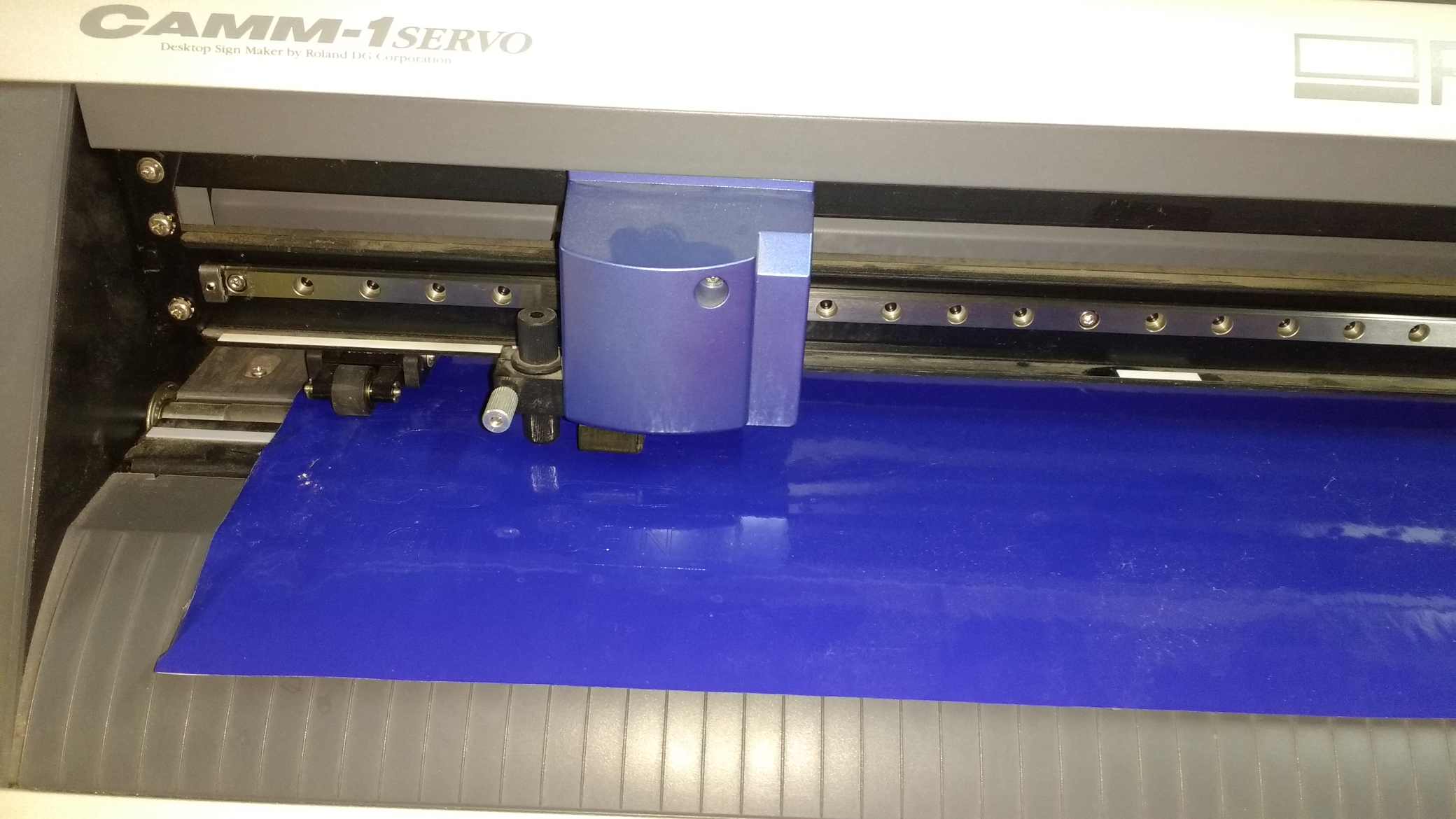
These are the functional parts of the roland vinyl cutting machine.

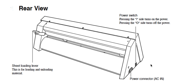
To place the vinyl sheet in the machine push down the sheet loading liver.
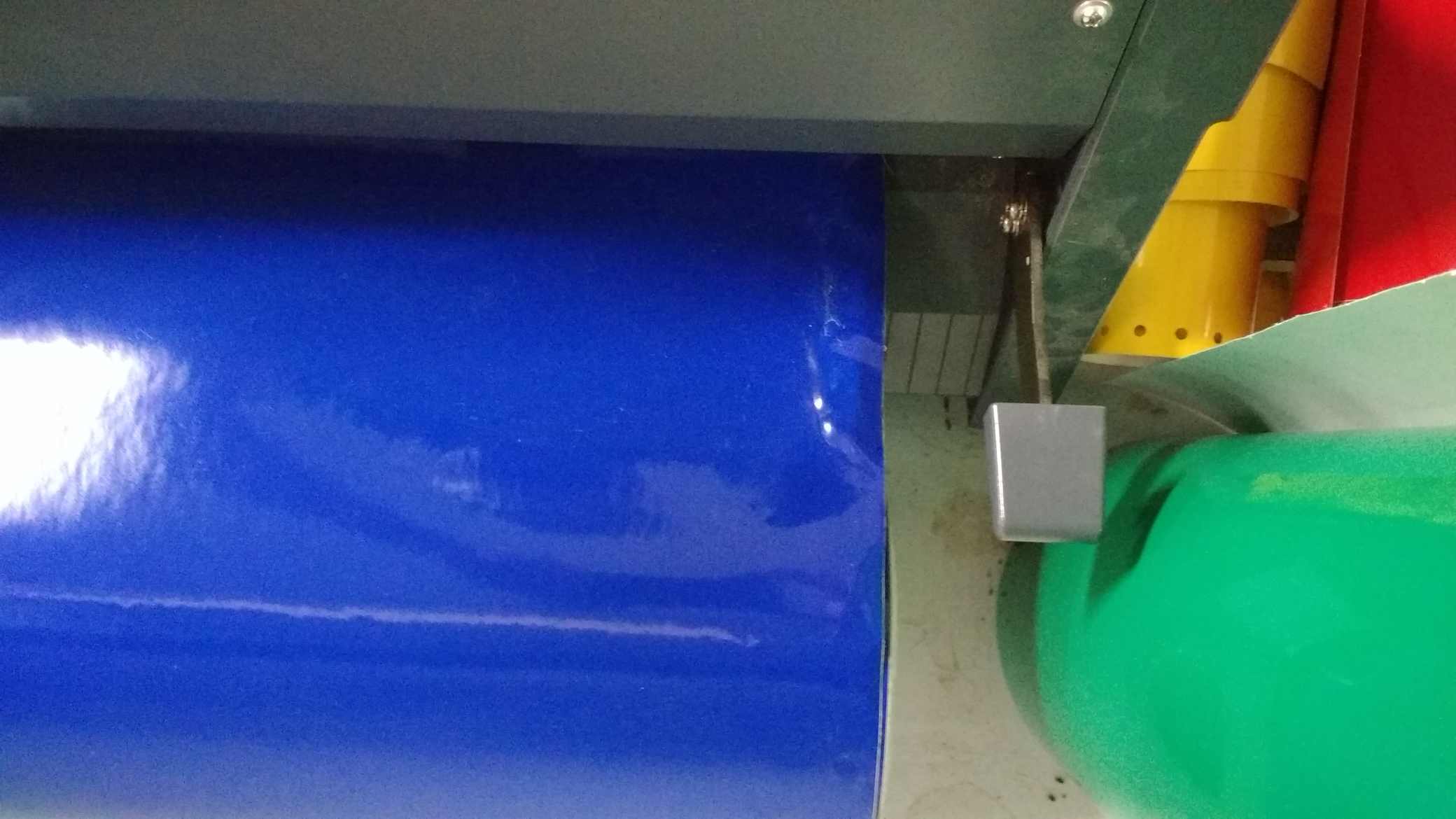
Place the sheet in between the rollers and pull up the loading liver.
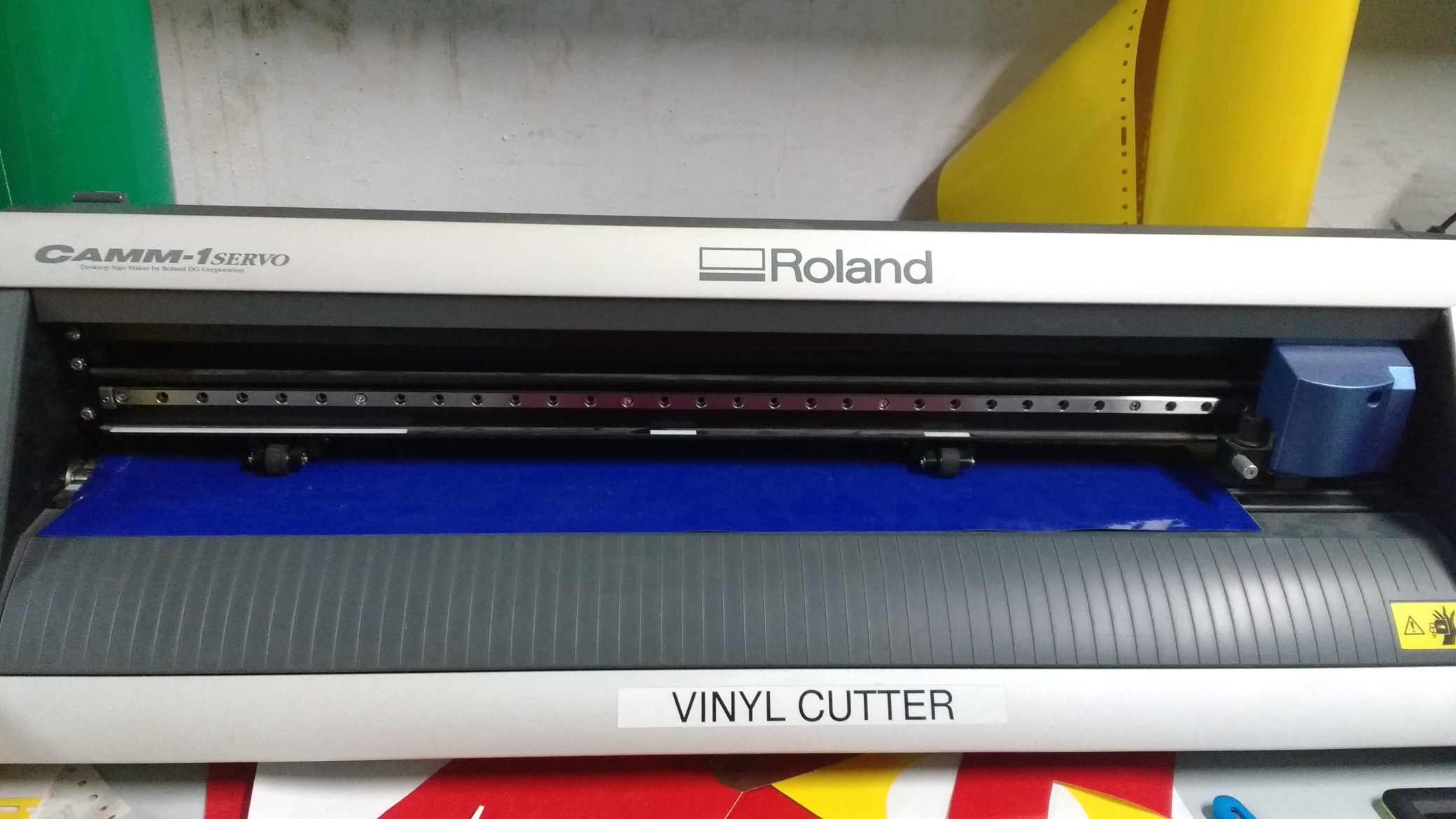
Always make sure that the pinch rollers are placed under the white lines and it is placed over the sheets also.
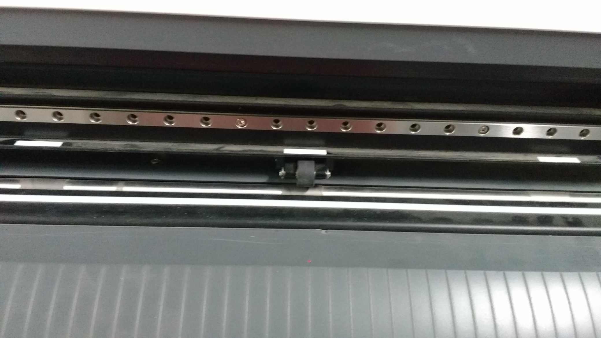
Make a test cut to ensure that adjucent parts could be peeled without any interference . if it is not working proerly adjuest the force on the machine or adjuest the screw which control the blade height.
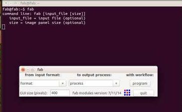
To start a cutting open a terminal and type "fab" .From the window opend select Image(.png) as format and Roland vinyl cutter as process.select "make_png_cam"
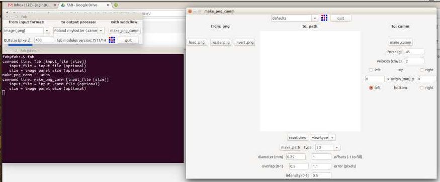
Select load png and open the required png file.
select the setted vinyl as tool and go for make path.
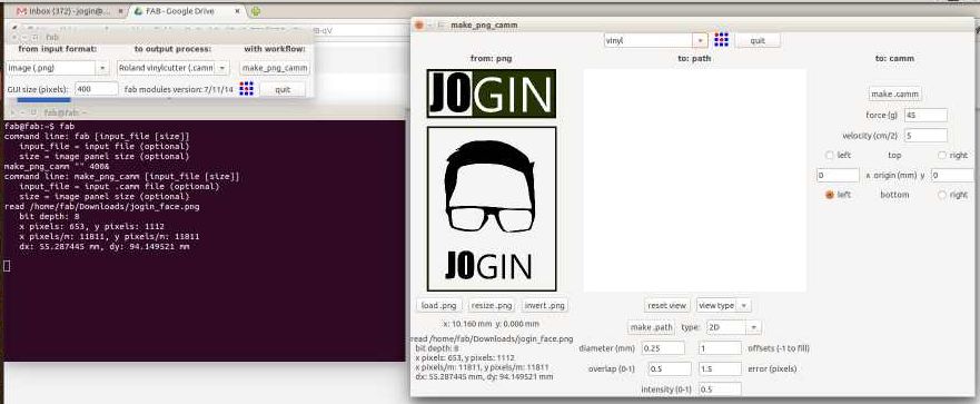
verify the path and make sure everything is fine .
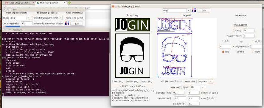
Set the force and velocity properly according to your test cuts . I have choosen force as 45 and velocity as 4 cm/second.there after move the head to the proper position to set origin double press on the origin button to set the position
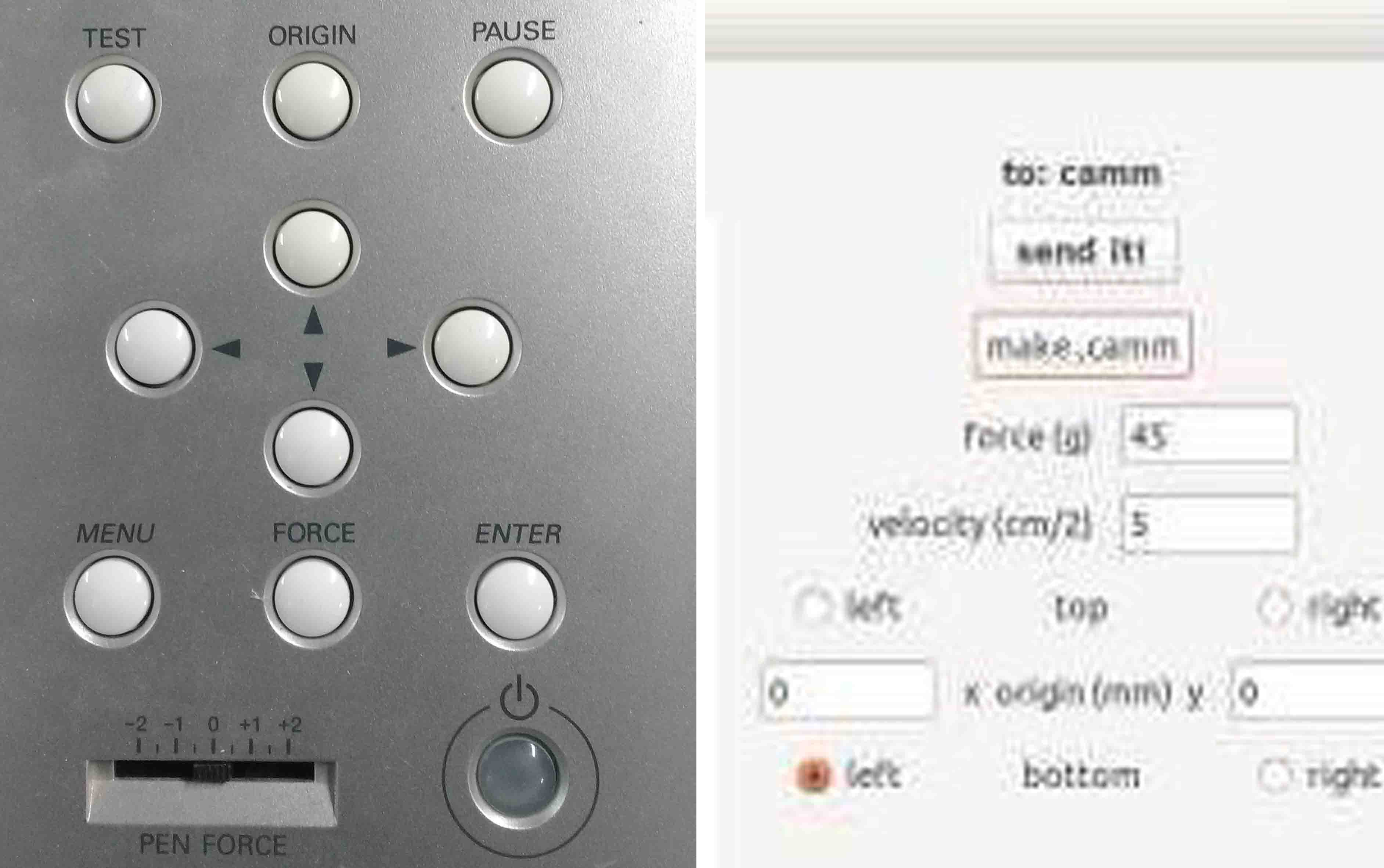
Press the "make cam" and there after press the "send it" button on the software.
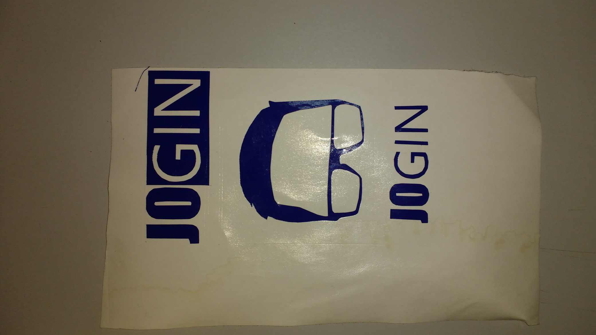
After completing the cutting remove all the unwanted pieces from the sheet.
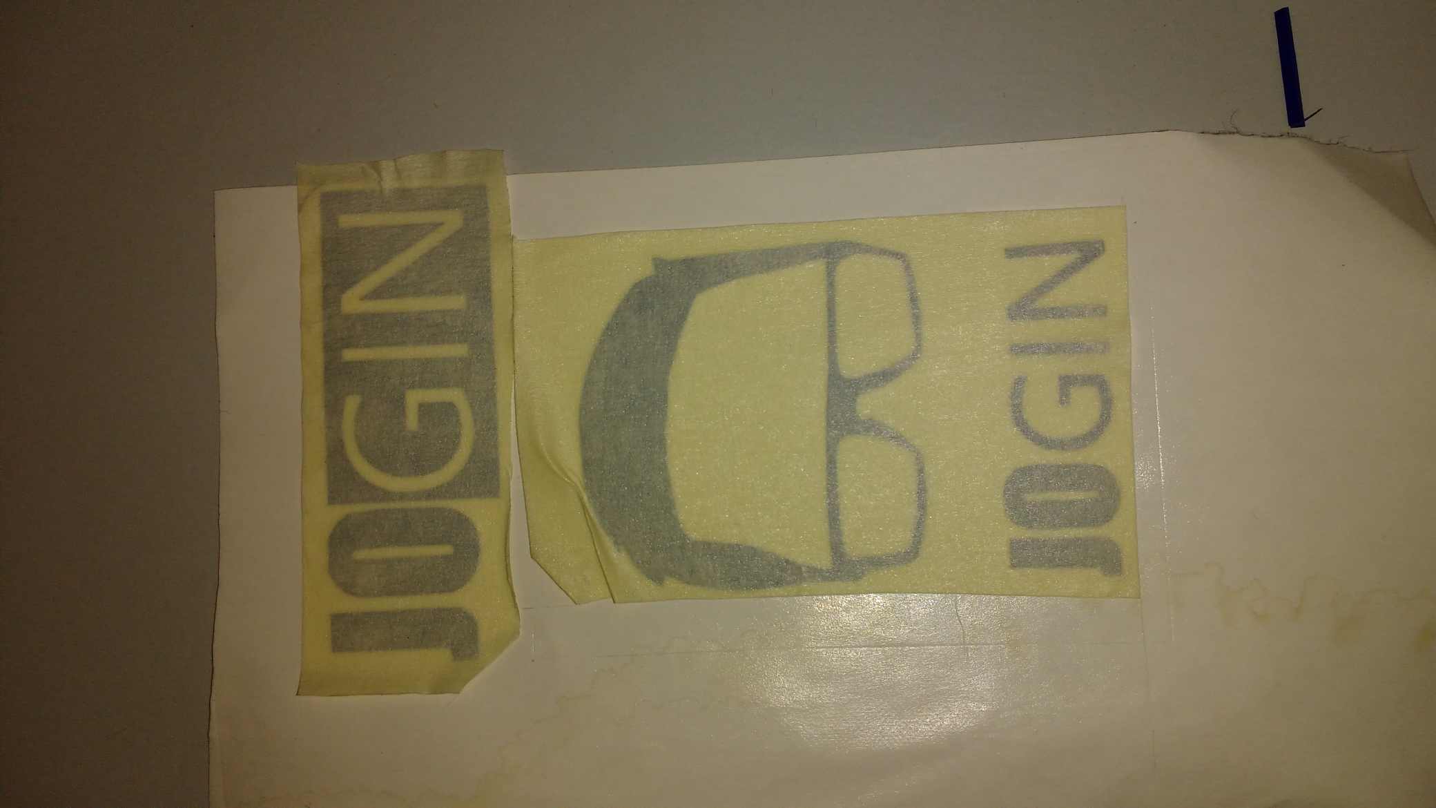
Stick a piece of masking tape above the required parts and carefully remove each parts.
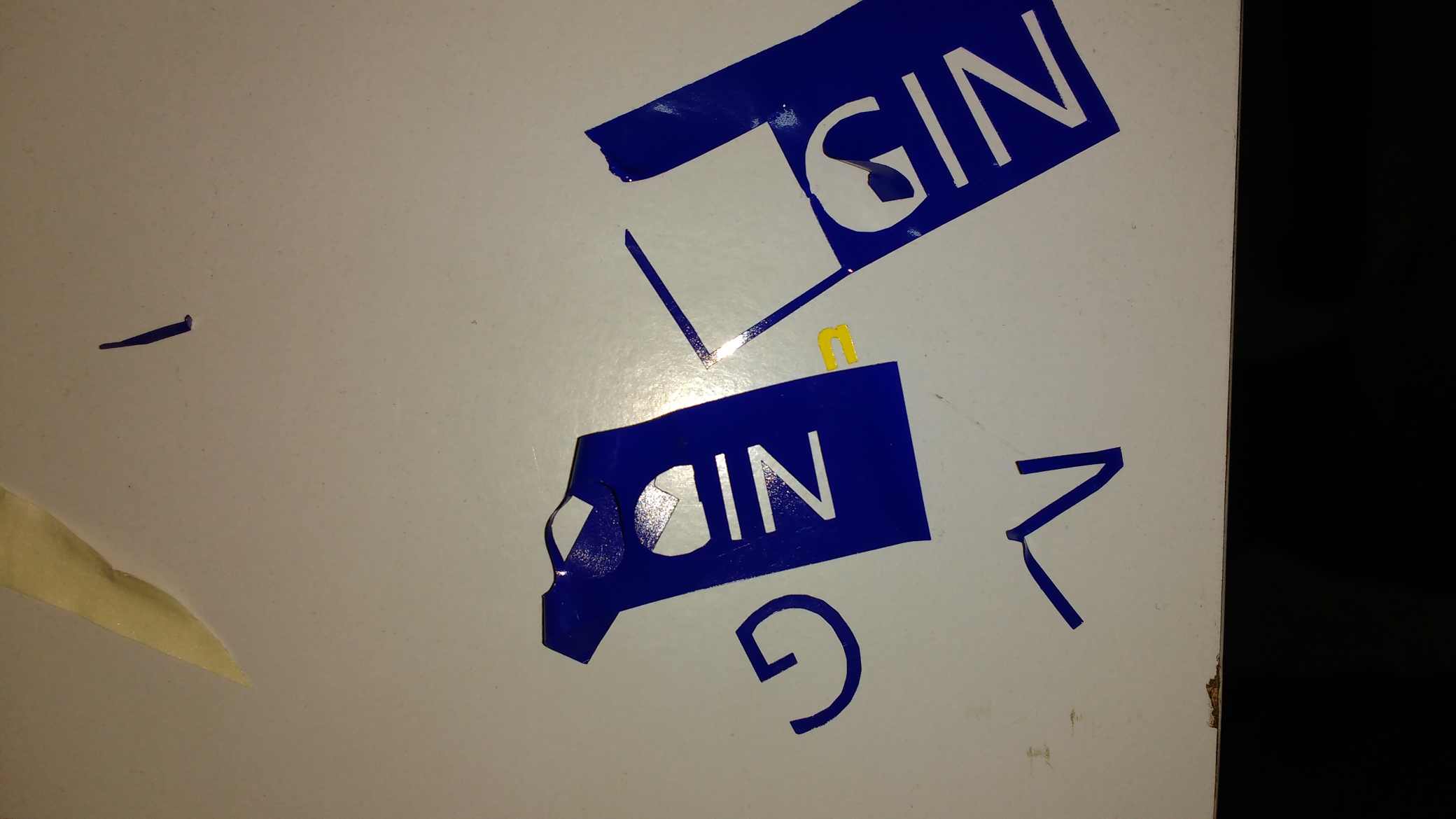
Mistake is a certain guest. The parts I designed were too small to seperate I couldn't able to transfer them properly.

I cutted a new piece again. This time some how it worked. I put my stickers on my powerbank.
These are my designe files.

You can download the files from here.
Computer aided laser cutting is a manufacturing technology normaly used to cut sheet metals, acrylic, cardboard etc.Basically a laser cutting machine workes by focusing a high energy beam of photons in to a single point .The focused beam vepourise the material where it falls there for the successive movements of the focus point in a sheet creating a cutting path
In our lab we use a trotec speedy 100 laser cutter
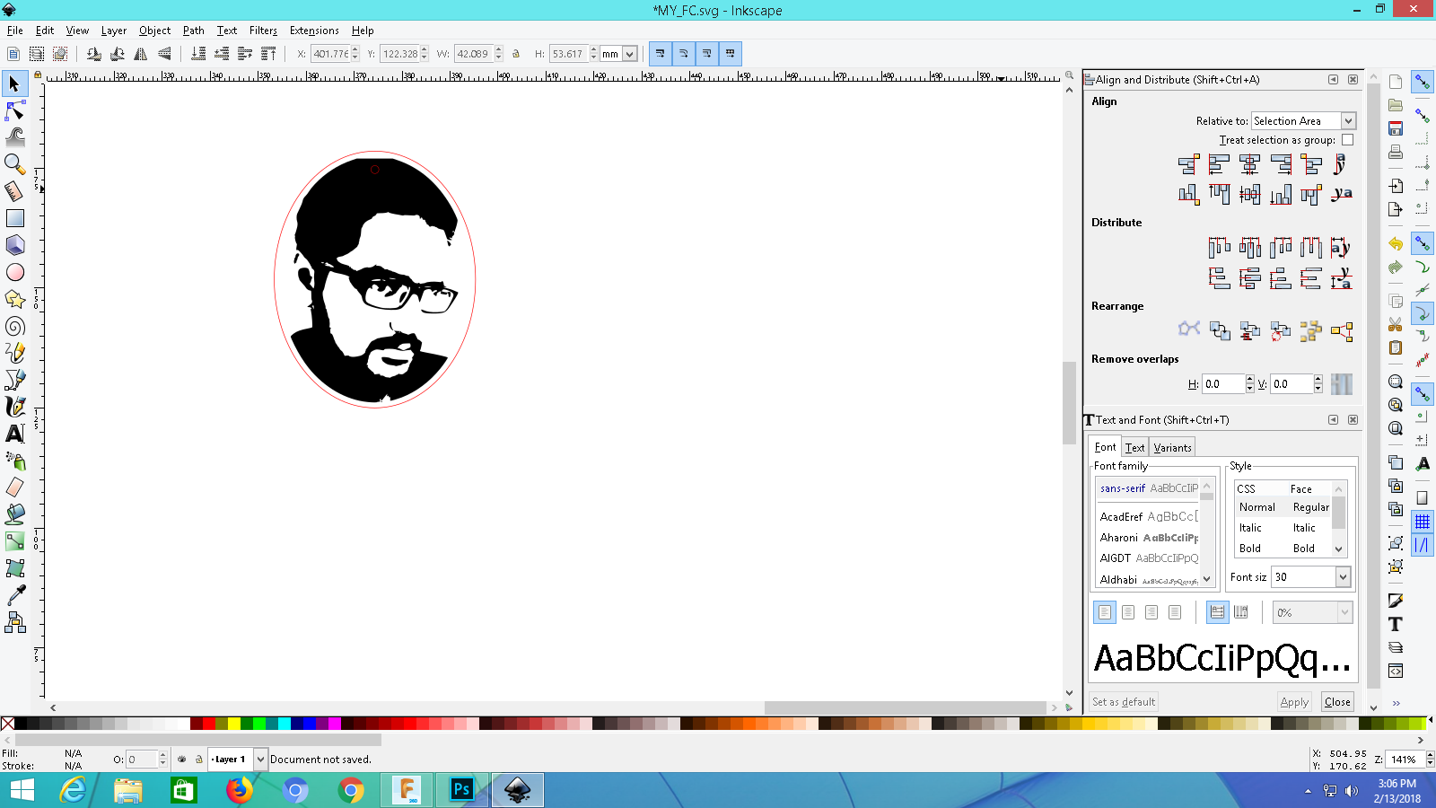
As a test cut I decided to engrave a photo of mine in a piece of wood.i decided to use inkscape for making the vector file .I took a photo of mine and opened it on inkscape. Go to the path menu -> Trace Bitmap -> Choose gray (Scan in 8 steps) -> press ok . Choose one with suitable brightness and contrast.Remove the unwanted images.
In our laser cutter the cutter will engrave all the black coloured components and cut through the red coloured components. Since I wanted a locket I draw a red elips arround my image to cut in that shape.
To focus the laser.
.jpg)
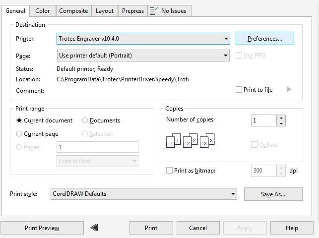
Select to print the document(Ctrl + P).Choose "Trotic Engraverv10.4.0" as printer
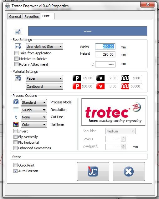
Go to preference -> print -> material Setting -> paper/plastic/wood and their corresponding thickness -> proceed to print.
The trotic software will popup .From the list choose our file .Double click on the file and ensure wether the proper file is choosen.
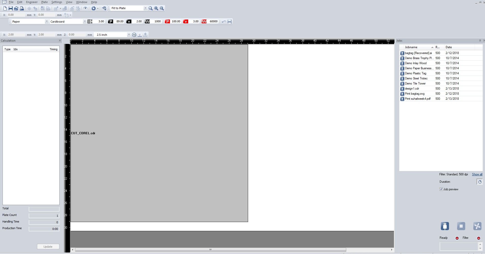
By jogging on the keypad move the laser head to an appropriate position
.jpg)
drag the file to the newly choosen origin.
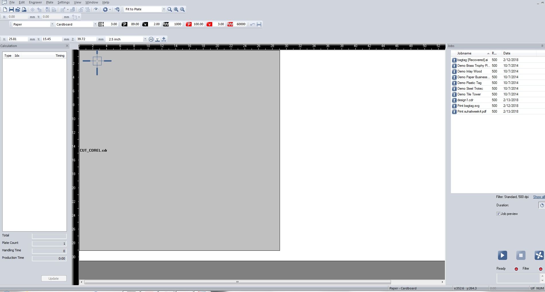
The machine will start to engrave 1st and later will move to cut the elips.
.jpg)
My completed keychain.
.jpg)
And Mistakes are a part of life. Since the color I chooed in the previous trys were not black so the machine didn't recognized them .
.jpg)
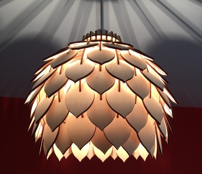
I have a little pasion for interior designing .I also done some gypsom and MDF works before .So initially I thougt I should do something in that area.I decided to design a lamp shade .Some thing like this
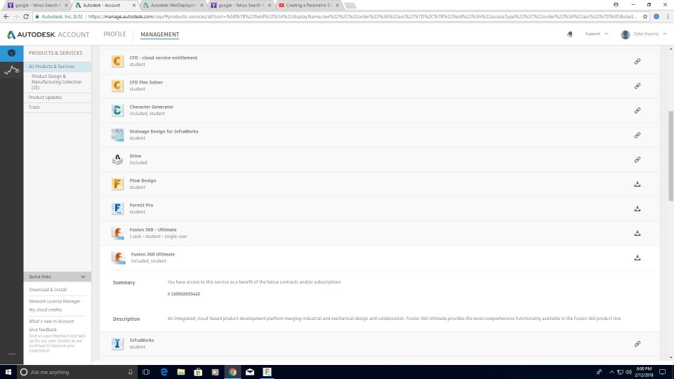
I choose to use autodesk Fusion 360 for this project . Fusion is free for 3 years for students . So i go to my autodesk accound and downloaded it .I is much easier to install and use.
I go through a quick introductory session .Allmost all the commands are self explaining also in addition to that if you hover the mouse pointer above a button a short animaation will popup to show the use of that tool.
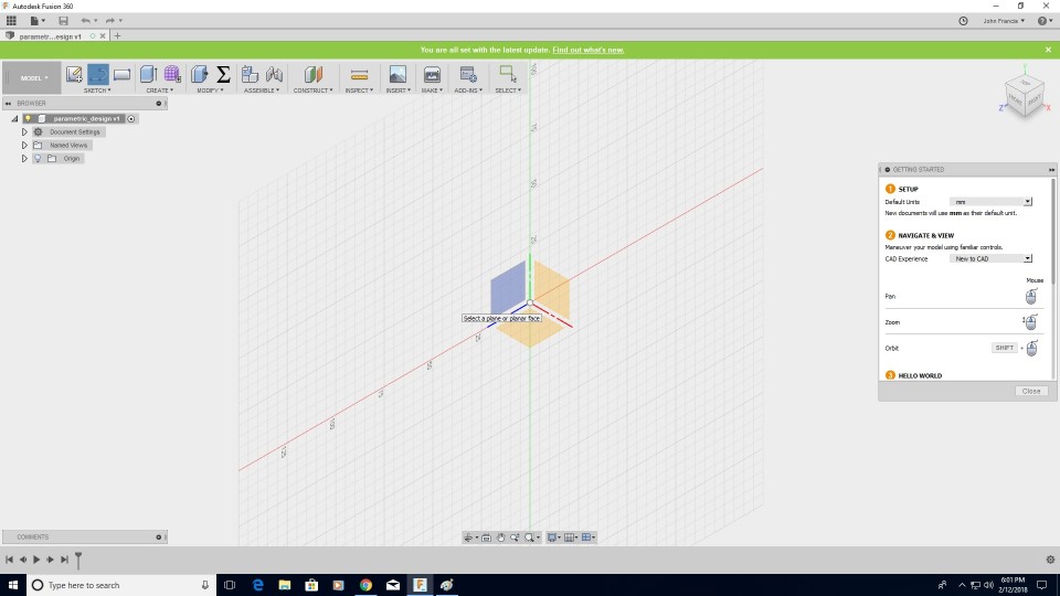
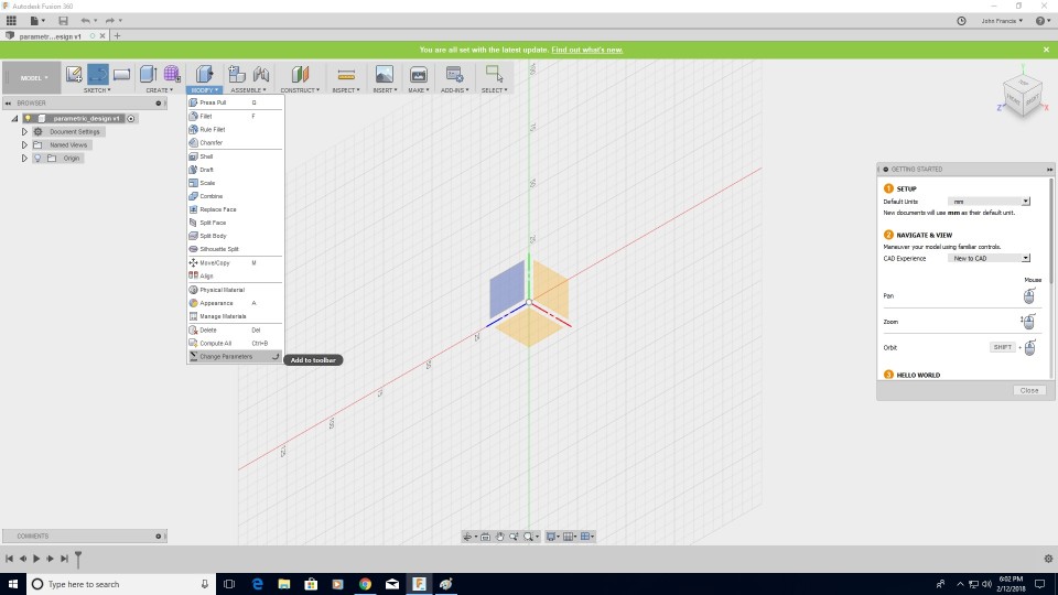
Since we have to do parametric drawing I decided to set some parameters initially itself. Go to the modify -> Change Parameters
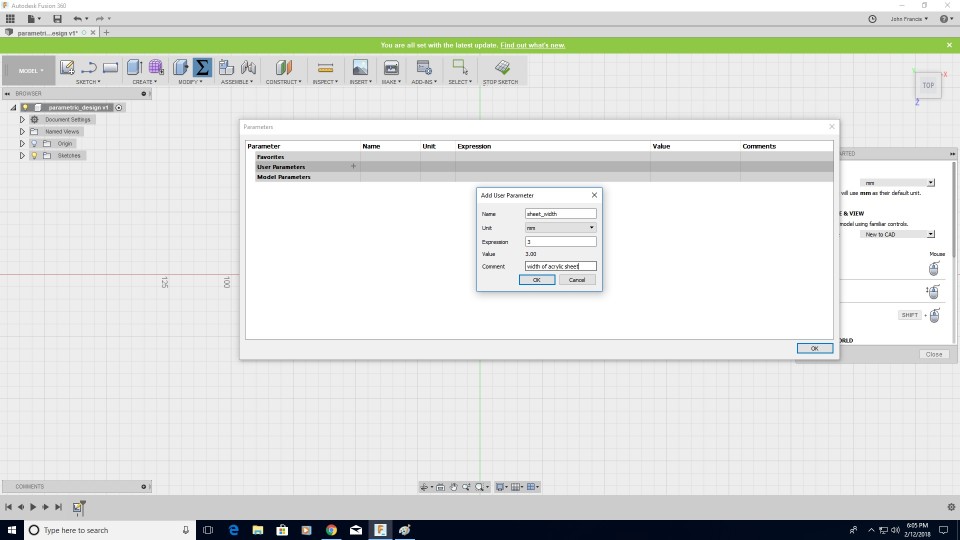
Click on the "+" symbole next to the User Parameter menu.A window will popup named "Add User Parameter". Give a name to our parameter ,choose the unit and provide an expression or a value to the parameter .If we need we could provide additional hint comments to tha parameter.If we are using autodesk dynamo-studio(Similar to Grasshopper in Rhino) we can directly link these parameters to dynamo and could create some creative computational models.
I created some essential parameters and started my designing.I wanted to populate my designe my lamp shade with different sized leafs .So I wanted to change the size of my leaf except the 4mm grove at the top when I change the width of my leaf. I designed every other parameter of the leaf as a function om my width .Now if change the width of the leaf The whole leaf will rearrange itself by keeping the aspect ratio and the width of the grove unchanged.
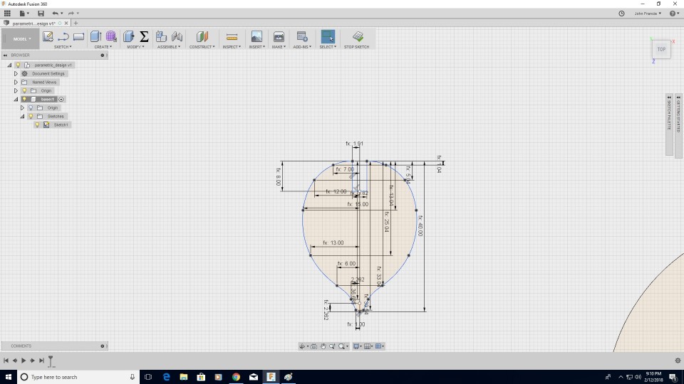
Up on moving forward I found that I need more time to complete my assignmet .Since I didn't Had the Luxury of time I decided to choose a little simple one for now.
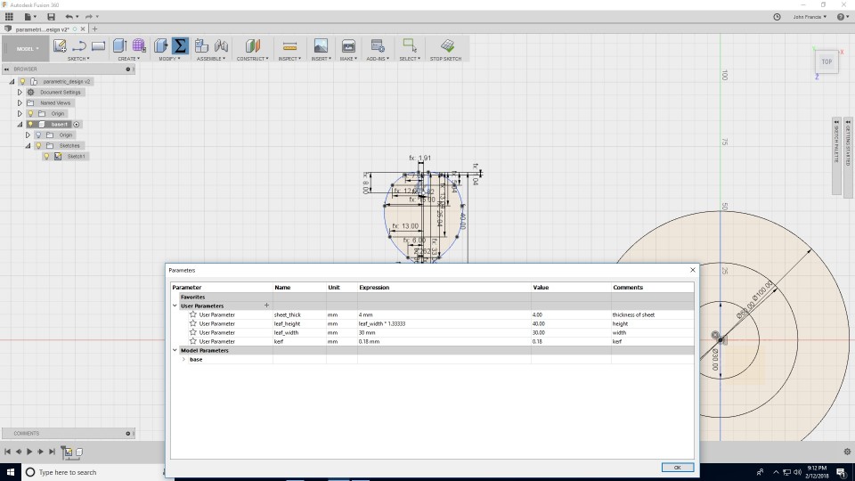
I have learned a lot about fusion by now .So designing a new one was not that hard for me. I decided to make a lego like structure that can morph to different shapes by rearranging the individual blocks.
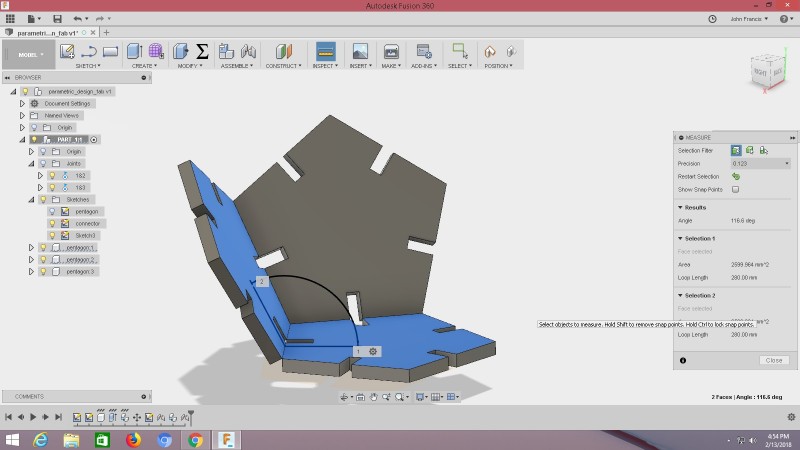
My design consist of 2 shapes a pentagonal build piece and a "L" shaped linking piece.It is much harder to calculate the angle of the "L" shape by manuel calculation. There I found the easynes of a designing software. I cauld easly assemble the components in a 3d space and there after I cauld able to measure the angle between them using Inspect -> measure.
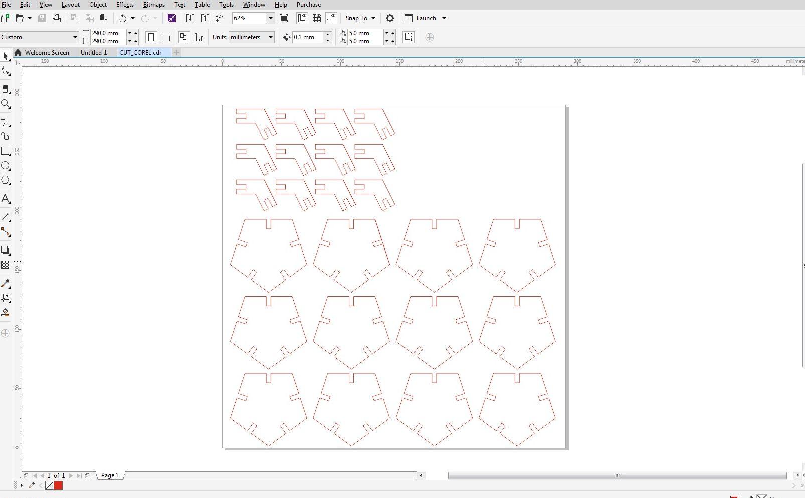
For the easynes I opened the file in Inkscape .I changed the colours to red and joined all open vectors.
The end results are Given below.
.jpg)
.jpg)
.jpg)
The laser burns away a portion of material when it cuts through. This is known as the laser kerf and ranges from 0.08mm – 1mm depending on the material type and other conditional factors. Although above c0.45mm is only experienced when cutting thicker foams. Any areas in our design where cut lines come closer than 0.5mm together could burn away entirely. Any details narrower than 1mm are likely to be very fragile and in some cases can cause the material to warp whilst cutting. As a benchmark, the recommended minimum cut widths be no smaller than the corresponding thickness of the material. For example, if cutting from 3mm acrylic, it’s best not to allow any widths less than 3mm. We can go smaller but this can make your pieces very fragile which might not be suitable for our application.
Kerf is determined by material properties and thickness. But other factors also have an impact on how much the laser takes away. The focal length of the lens, pressure of compressed air both have an impact. Kerf widths can vary even on the same material sheet, whether cutting a straight line or a curve line or from laser cutting in the x or Y dimension. The manufacturing tolerance of the material can also impact the kerf.

| Materials | Thickness | Average Kerf |
|---|---|---|
| Acrylic | 1mm-3mm | 0.18mm |
| Acrylic | 5mm-8mm | 0.21mm |
| Acrylic | 10mm-15mm | 0.3mm |
| Acrylic | 20mm | 0.32mm |
| HIPS, PETG, Styrene, | 1mm-3mm | 0.45mm |
| Birch plywood | 0.8mm | 0.08mm |
| Birch plywood | 1.5mm | 0.16mm |
| Birch plywood | 3mm | 0.2mm |
| Birch plywood | 6mm | 0.22mm |
| Birch plywood | 12mm | 0.3mm |
| MDF | 3mm | 0.16mm |
| MDF | 6mm | 0.2mm |
| MDF | 12mm | 0.28mm |
| Veneered MDF | 6mm | 0.17mm |
| Greyboard | 1200microns | 0.08mm |
| Greyboard | 2400microns | 0.12mm |
| Paper | 90 – 350 gsm | 0.08mm |
| ENGRAVING PARAMETER | CUTTING PARAMETER | |
|---|---|---|
| Power | 75 | 75 |
| Velocity | 90.00 | 0.90 |
| Freq | 500 | 5000 |
This is our kerf scale By inserting a piece of acrylic in each slot we cauld find the dimension for perfect press fit
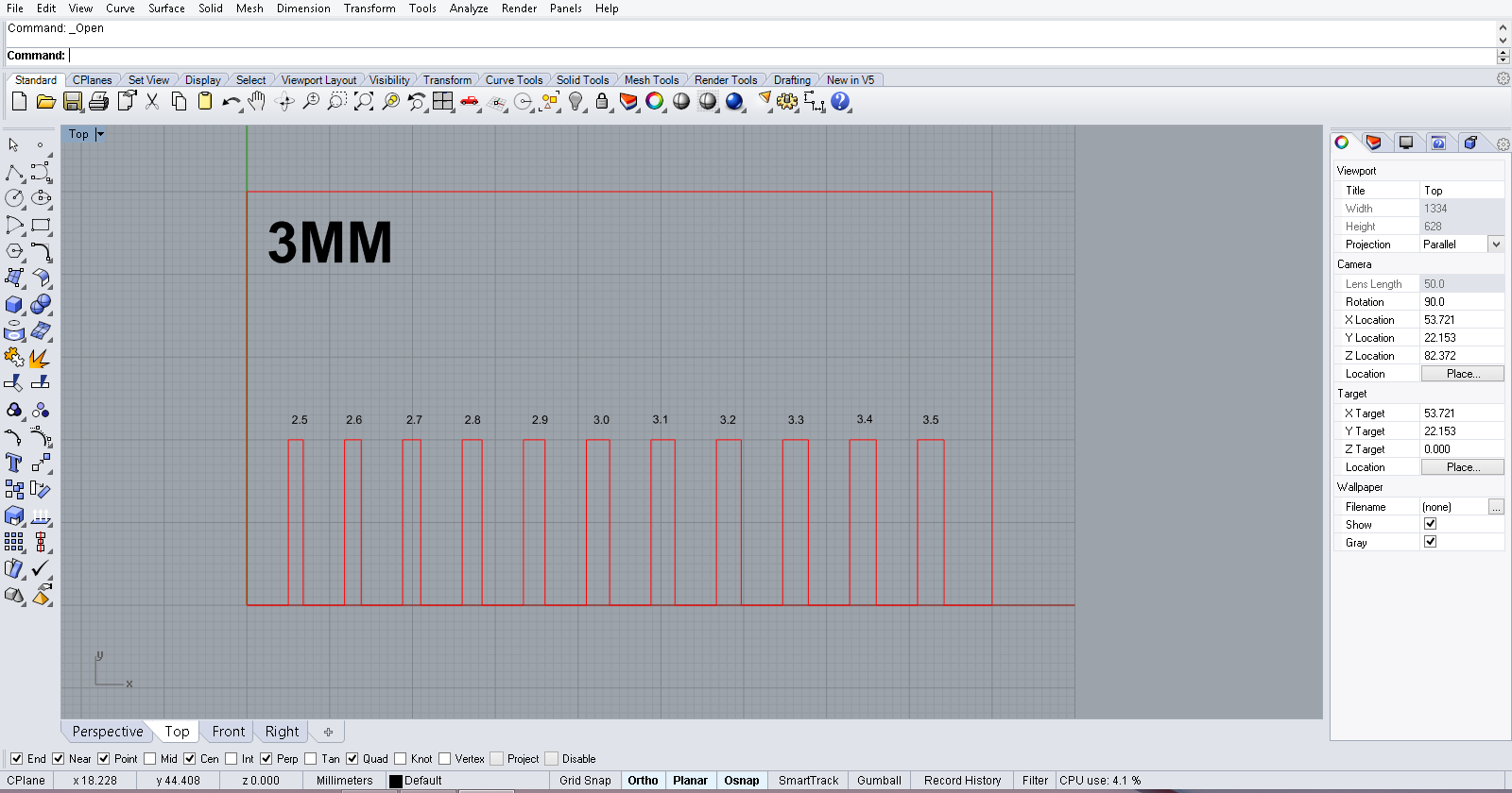
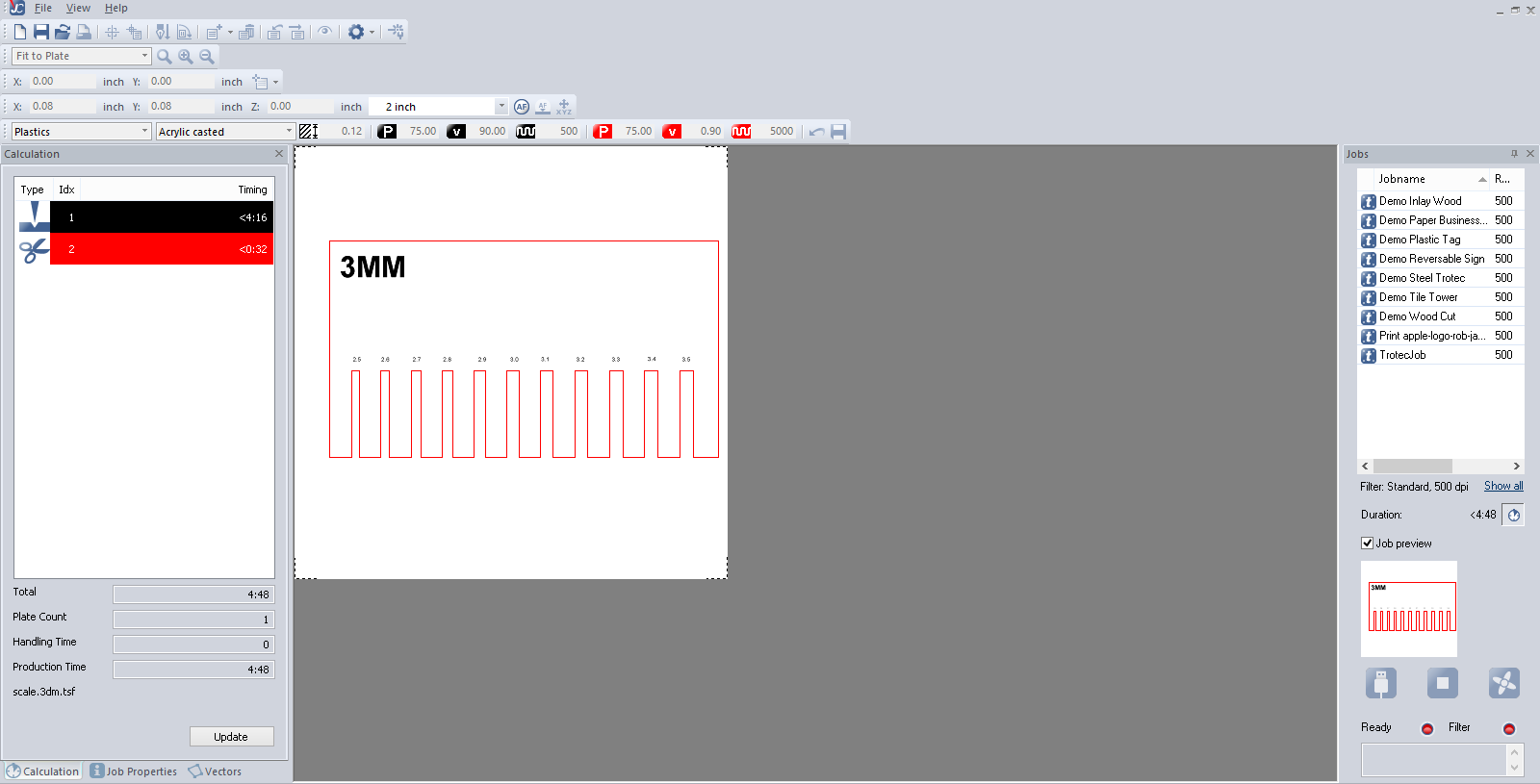
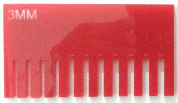
The kerf we got in our lab is 0.20 mm.