What do I need to do this week?
Customize my board
Software used:I decided to make the Neil FabISP version because in my opinion the USB connector is more stable than a pendrive model. Here's how it looks like:
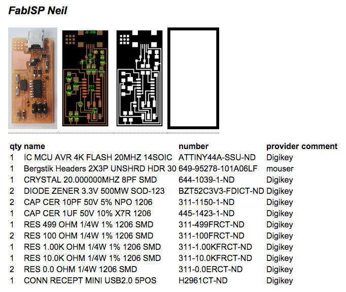
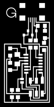
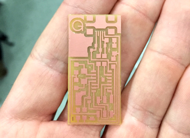
So I made two modifications in PNG file with the milling traces, first I changed the MIT logo to my logo, and second I removed the white border to reduce the milling time because this trace will be cutted in a second step. Here's the result:
Milling
Software used:Tips:
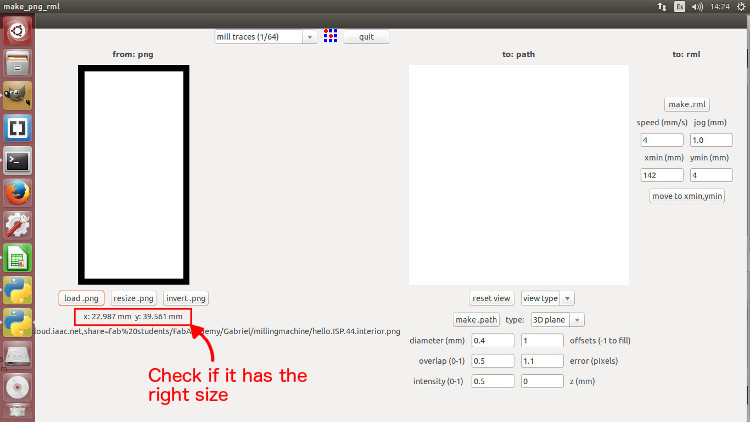
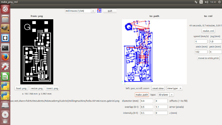
After the Z alignment I loaded the PNG file with my logo and adjusted the settings in Fab Modules to sent it to cut.
FAIL: I had exported the PNG file with 72 dpi and the original file has 1269,448. Basically the image size became bigger and the machine went to a different position from the previous origin and started to cut.
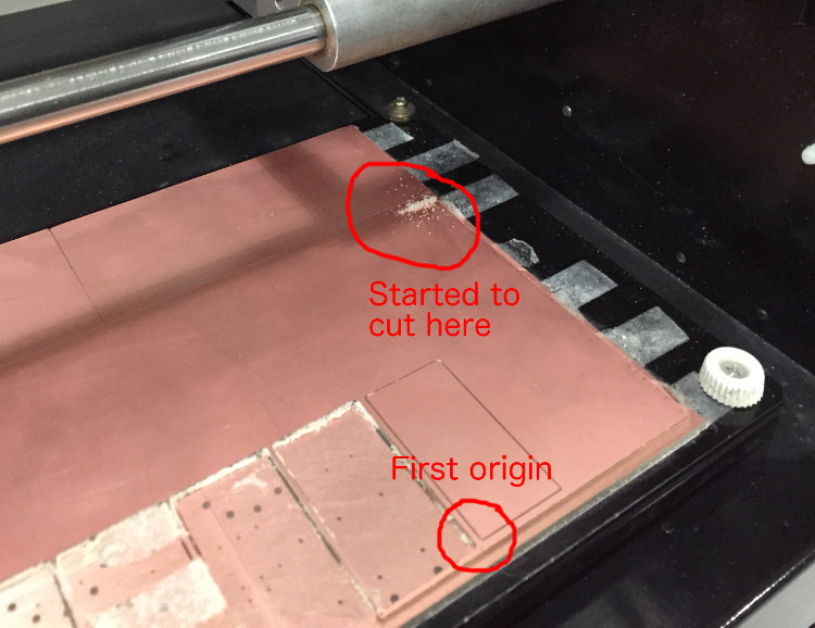
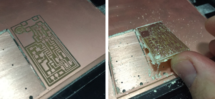
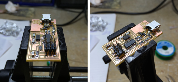
So I had to export a new PNG file and set the Z alignment again. Here's the final milling result:
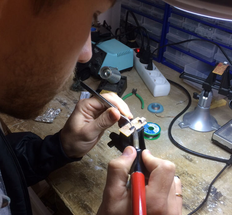
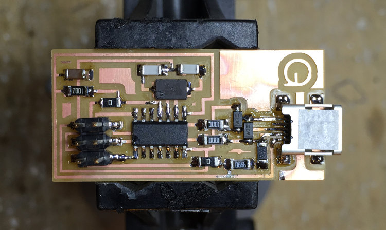
Stuffing
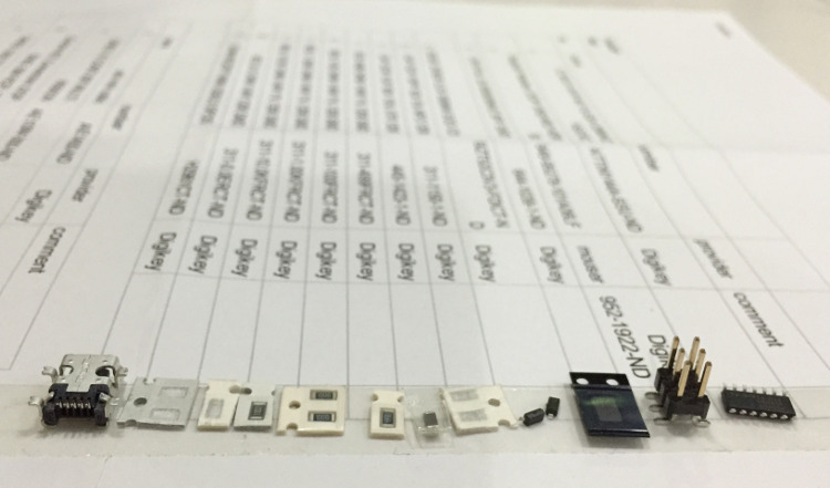
The first step was to separate all the components. To make sure that I wouldn't mix everything I used a double sided tape beside the components list:
Tips:
FAILS:
What I did to solve it?
Unsoldered these two components just heating the solder points with the iron and pulling with tweezers when the solder got in melting point, then I soldered again in the right position.
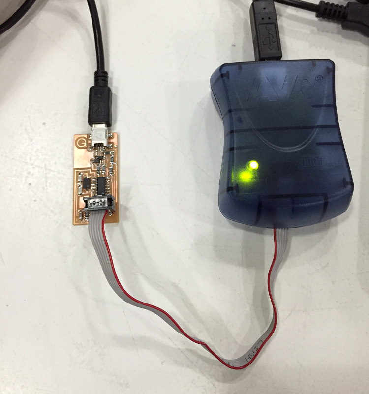
Programing
After soldering process I took risk because I pluged the board directly to my computer USB port, and after that I discovered that if something was wrong I could burned my board or my computer. Fortunately everything was fine, and my board is working. So, I did the tutorial for programing in MAC and I had one problem with Xcode installation, it didn't work in my computer. Then I decided to start programing without the Xcode to see what would happen, and what happened was when I did "make clean" command it asked for a software to be able to make the command and also asked if I would like to install it. I chose YES and after a few minutes it was done and I could finish the programing without problems.
| ← week 3 / computer-controlled cutting | week 5 / 3D scanning and printing → |
|---|