A Rotational Casting Machine for Fab Labs (Still in Development, Unfortunately)
General Design and Results
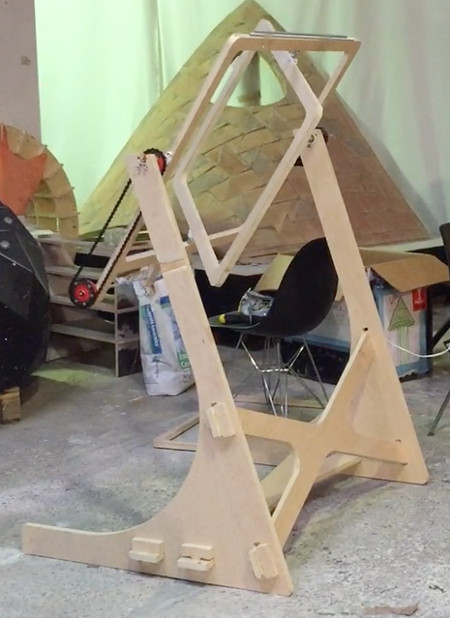
After two-three weeks of work, I have finally been able to bring together the rotocaster I have been breaking everybody’s ears about. A rotocaster is quite a simple machine that could be very useful for any fab lab – basically, it is a two-axis, rotational piece that allows to cast hollow pieces as well as various complex shapes – but the main challenge it represents is the subtle mechanical design it requires. It doesn’t involve anything too fancy, but a cumulative misalignment of a few centimeters can render the machine completely unusable, which is pretty much what happened in my case.
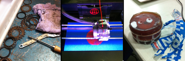
For the general design of my piece, I wanted to make something that could easily and cheaply be made (around 100EUR, as mentioned during the Application week) from widely available materials and technics. Apart from the machine’s electronic component, it can all be made through some milling, 3d printing and casting. I also decided to include some bike parts in my design, not so much because they couldn’t be reproduced or printed in any other way, but rather because it was quicker and cheaper to simply grab them at any second-hand bike shop.
In the end, everything came together quite nicely, but I would be lying if it’d say that the machine is currently usable. After MANY attempts, I would always run into the same problem – the bike chain going out.
I indeed made many tests and corrections – changing the bike chain, fixing the 3d printed pieces more solidly, moving them, adding weight at the other end of the outer frame, &c. – and I indeed went from the chain dropping after a single turn to the chain dropping after 6-7 of them, but I could never really make it actually usable.
The main problems of this first prototype is that the distance between the outer frame and the supports is too big, the holes within the edges are not straight enough and the bike bikes are a bit too rusty, which all together make it impossible for the bike chain to stay in place more than few rotations. I unfortunately do not have enough time to make a new, working version of the machine by the end of Fab Academy, but I am still confident that this piece constitutes a solid first iteration on which anybody interested in making a rotocaster can build upon. The only remaining element to figure out would be how to fix a mold to the machine, but I am sure that some screws with circular heads at each corner or two holed planes that can be tightened nuts and screws within the inner frame would do it. But anyway – here is a video of the stage at which the current iteration is at:
Neil, we are recording from Théo Richer on Vimeo.
Structure
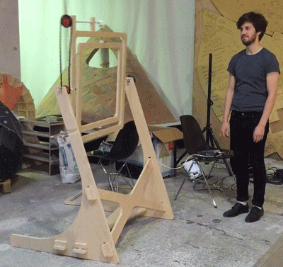
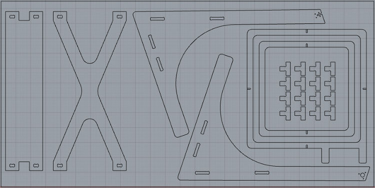
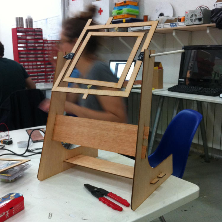
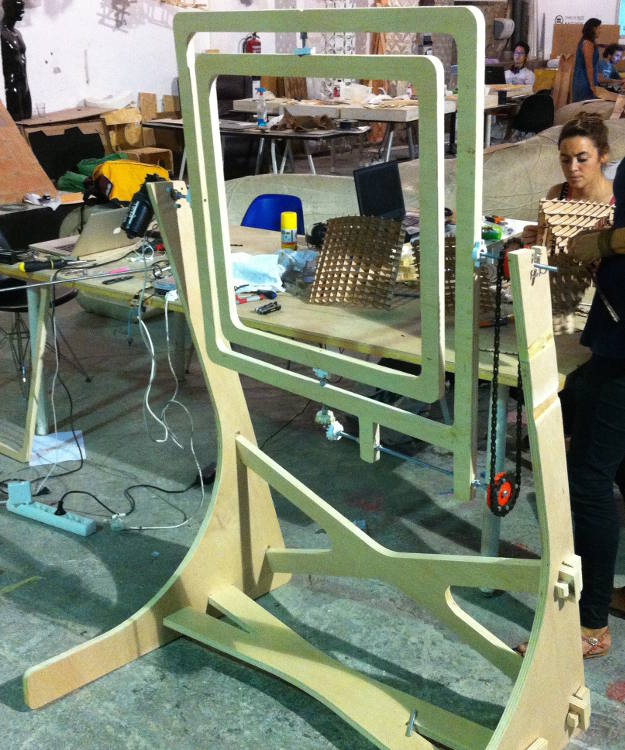
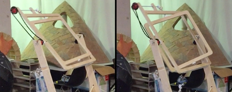
For the general structure, I gave myself the objective of designing a piece that could be milled out of a single 2500 by 1250 sheet of 20mm thick plywood and that wouldn’t require any screws or nails (well, the wood provider Fab Lab BCN works with ended up being out of sheets of this dimension when I made the order, but this still all works on paper). To do so, I started by drawing the two biggest frames that could fit on a sheet, and then designed the other pieces in consequence of the remaining space. To make everything hold together, I decided to have two cross-shaped supports at two different angles, which could be joined with the other pieces through wood splines.
While designing the structure, I made two tests in cardboard, which revealed to be extremely useful. In the first case, the test made evident that I had misplaced the holes for the wood splines and, in the second case, that the supports for the frames were out of balance. These mistakes might seem obvious, but there sure don’t look so when you are modeling/drawing on Rhino, so making these two small models proved to have been really useful.
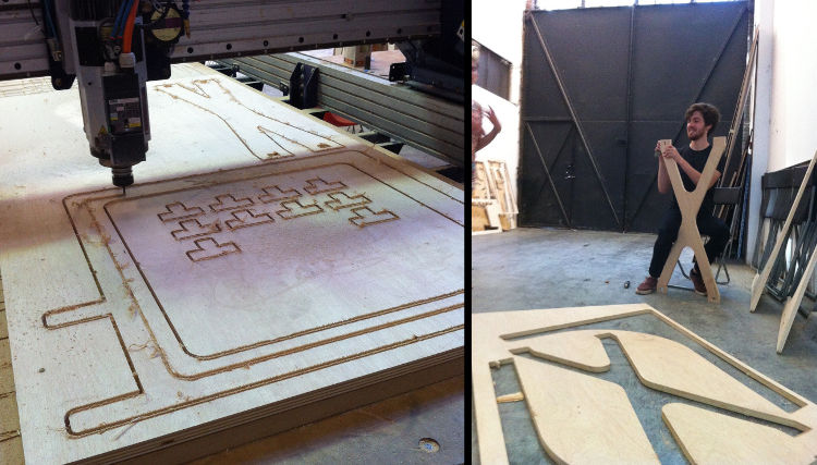
The following milling of the actual piece went well, even though the milling machine proved to be a bit miscalibrated – some holes lost their original proportion and some lines were milled from within while they were set to be milled from outside, but nothing that dramatically affected the usability of the pieces. I then carefully sandpapered everything and assembled the structure by joining everything with wood splines.
The resulting structure ended up being quite stable and the splines indeed made a good job at keeping everything holding together. If I had to redo this project again, I would drastically reduce the distance between the outer frame and its perpendicular supports. In my current design, there is in total 15 centimeters of space, which could easily be cut by half to assure a better alignment between the frames and the structure and consequently more stability for the structure as a whole. Despite all that, I could still reduce quite importantly the aforementioned instability by milling holes in the middle of the frames’ edges using the 4, then 6 and finally 8mm mills – that way, as the thread were more deeply inserted in the frames, I could assure a better alignment of everything.
Rhino file/milling pattern available here
Mechanical Design
To bring everything into motion, I had to find a way to translate a first rotational motion into a second, perpendicular one. A wiper motor directly connected to a first frame, establishing the first movement. This first rotation was made possible by a first 3d printed piece screwed into the frame – a piece pushing the frame as the motor goes – as well as a second one containing a bearing connected to the other end of the structure – allowing the frame to spin freely.
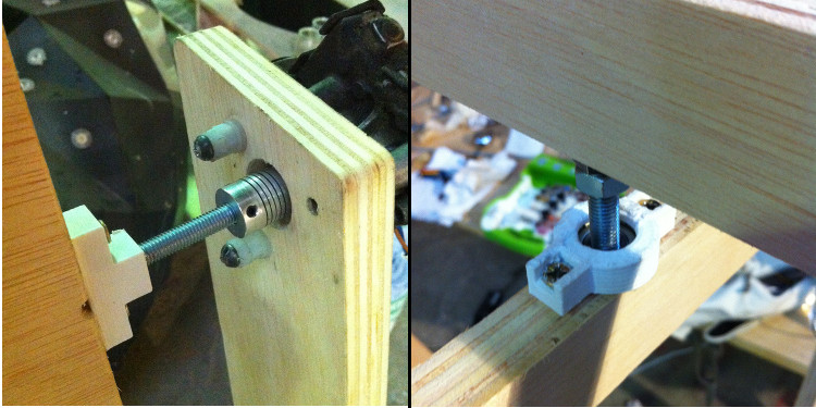
The second rotational axis was made possible by a series of other pieces: a first one directly fixed into the structure that contained a bearing and held a bike chainring, a second, rotating one holding a second chainring and finally two pinions changing the orientation of the movement. In the first two cases, I struggled a bit to find a design that would minimize hangouts and the like, but could in the end manage to make two usable pieces (Pretty? No. Usable? Yes.). I 3d printed them with a filling of 60% so they would be strong enough to support the pressure, but had the bad surprise of realizing that the printers tend to make holes smaller they intended, as the PLA can freely expand when there is nothing around. The bearings and threads could therefore not fit into the pieces, and I had to smoothen the pieces using a sandpaper header installed on a small drill.
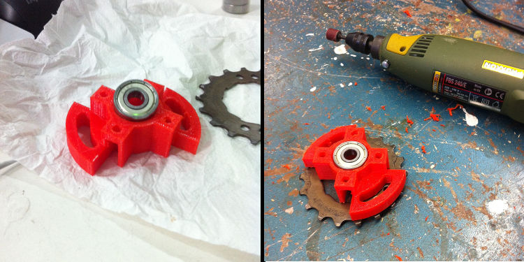
For the two pinions, molding and casting them proved to be a better idea as they were identical and required a very high material resolution. I indeed had some problems with casting them, which I already reviewed during the Molding and Casting week, but nothing that stopped them from being usable.
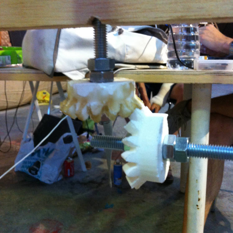
Put in motion, all these pieces allowed to smoothly change the axis of rotation. As the first frame turns, a bike chain connecting the two first aforementioned pieces makes the second one rotate in the same axis as the frame. This second piece being attached to a thread passing across the two top parts of the first frame, its rotation makes the thread itself turns, including the first pinion attached to its other extremity. As the latter spins, the other pinion connected to it at a 90 degrees angle starts to spin as well, changing the orientation of the movement. This movement is then transmitted to the second frame through a thread passing across the first one, and the second frame starts spinning using the same two aforementioned pieces used to make the first frame spin.
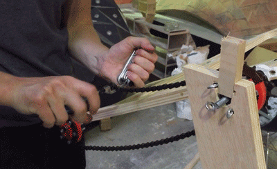
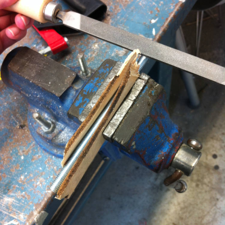
All these parts were then brought together using 8mm metal threads. To make the threads hold solidly into the 3d printed/casted pieces, I cut a third of them using a file and insert them into the pieces that had been already designed to receive such a shape. The only exception is the pinions that I had wrongly designed for 10mm thread instead of 8mm. To resolve the issue, I not only cut the third of the threads but also casted some epoxy into the pieces when in place, so they would have a strong grasp upon the cut off part of the threads.
All in all, the main challenge in designing all these pieces was, in the case of the 3d printed one, to avoid overhangs and the like, but, after some puzzling around, I could come up with designs that could all be easily printed. Of course, the main issue remains – the alignment of the bike chain is still a problem, but, if I had the time to redo my rotocaster again, I am sure that reducing the distance between the structure and the frames as well as using better bike components (the chain I used is pretty much scrap and the chainrings have too many jumpers to make the whole thing stable) would make the machine spin smoothly.
Rhino files/printed and casted parts available here
Electronics and Programming
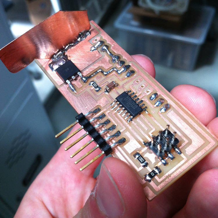
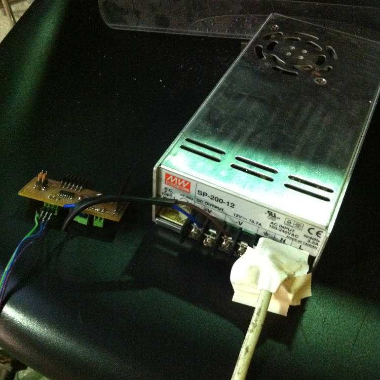
As the standard wiper motor requires 5A/12V, I couldn’t simply reused my board from the output week and therefore designed, milled and stuffed another board using an Attiny44 to send PWM to a 16A-MOSFET. To do so, I referred to Ferdi’s Fab Academy page – for he went through a similar process during his Machine Design week – and added few additional input/output headers to suit a potentiometer and any other input that I might have wanted to add at some point.
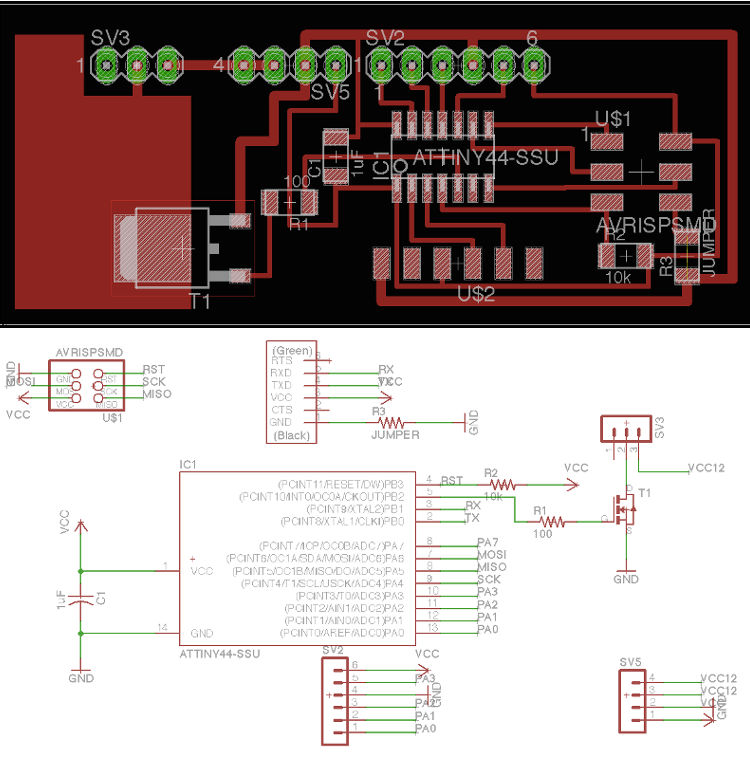
The only problem I ran into during this part is that the MOSFET would quickly get really hot when in use, but I could easily reduce the gravity of the problem by soldering perpendicularly to the MOSFET’s GND connection an additional sheet of copper. The final result proved to be quite efficient, but, if I had to do it again, I would connect the 5V VCC to the 12V VCC through a NOPBCT-ND 5V regulator to avoid having to connect the board to both a 12V power source and a 5V one through FTDI (such as a computer).
For the programming, I heavily relied on what I had already coded during the Output Devices week, i.e. a simple Arduino script mapping/translating a potentiometer input into a motor output through the map and constrain functions. I indeed tried to code the whole thing in C (well, Arduino is C as well, but let’s just say that I tried to write it without the additional level of abstraction that Arduino provides) but couldn’t understand how to establish a relation between an input and an output.
I therefore stayed with that first script and went through a lot of trials and errors to find the right values for the output, as wiper screen motors might indeed be stronger and slower than most other motors that can bought at scrapyards and second-hand car pieces shops, but they still spin way too fast for the needs of a fab rotocaster. After having tried different values, I settled on a magnitude of 70-100 out of 255, which allowed for a reasonable variation in the speed of the rotocaster.
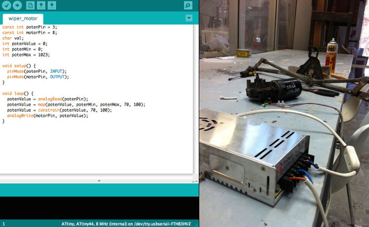
In the end, the board became pretty much nothing but the intermediary between the motor and the power source… quite literally, as the motor’s VCC and GND pass directly by the board. The motor is constantly connected to the board’s 12V VCC, and the MOSFET’s job is to connect the motor’s second cable to GND when needed, which it does following the PWM from the Attiny44. This ratio is in fact extracted from the value received from the potentiometer, which is then translated into a connection per second ration made out by the Arduino script.
EAGLE files/board schematics available here
Arduino file/code available here
- Week: 18&19
- Subject: Final Project Presentation
- Tools: Rhino, ShopBot, Modela, Molding & Casting, Makerbot, Eagle
- Objective: Document a final project that integrates the range of units covered
- Files: Click here