Théo Lepage-Richer

Fab Academy / Digital Fabrication 2015

A Twist for a Spin: Controlling a DC Motor with a Potentiometer

You remember last week when I was boasting about my soon-to-be very own Théoduino? Well, I kind of ended up putting it on hold. I spent one day trying to do some troubleshooting, to then simply realized that designing and refining such a piece could be a final project in itself, and that I might as well focus on my current project rather than dividing my attention. Ok, developing a new Fabduino is indeed quite cool, but an open-source rotational casting machine can be AS cool… right?

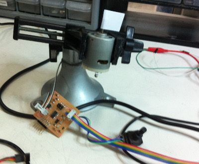
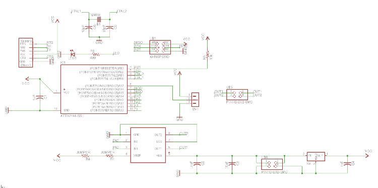
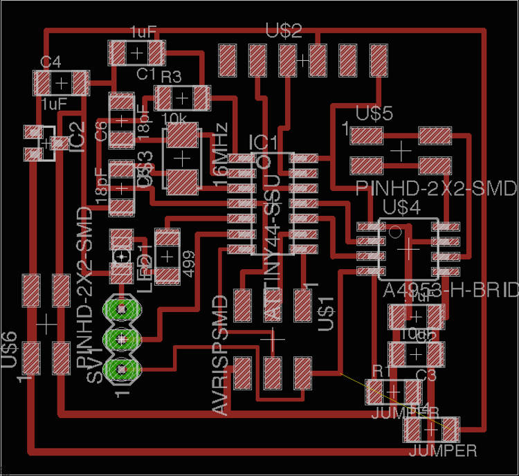
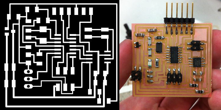
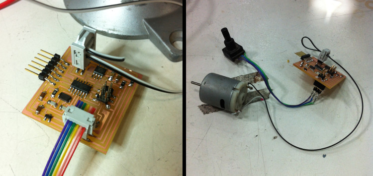
I therefore dedicated the rest of the week to the development of what could be the electronic component of my final project – a piece translating a potentiometer input into a DC motor output with various speeds and intensities. The design part went flawlessly, as I mixed together my pre-existing potentiometer board and Neil’s DC motor one. The resulting board affords one analog input pin, a digital pin connected to a LED to signify the begin and the end of the board’s calibration, two analog pins connected to a H-bridge motor driver, and two additional headers to, respectively, connect the board to a motor as well as to an external source of energy (5V not being enough to furnish the motor in energy). Click here for the Eagle files.

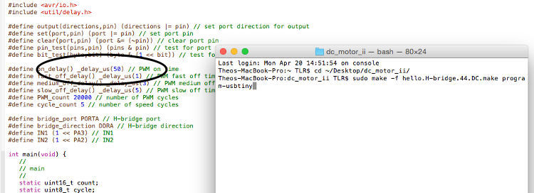
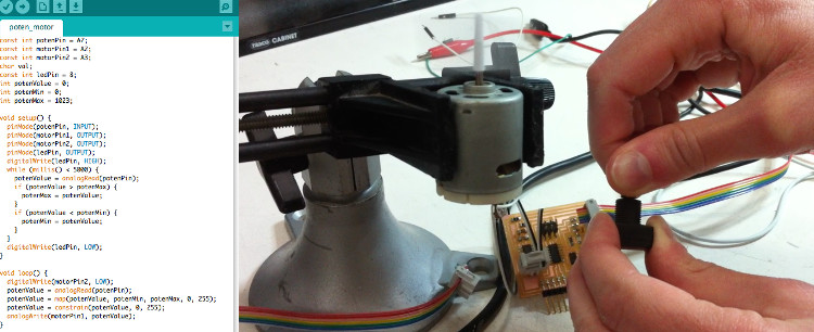
This first part went well, and I could quickly start to experiment with different scripts. In the first case, I made sure that my board’s input worked by uploading my script from last week, to then try Neil’s C-code, DC motor sketch and did some troubleshooting with it, and finally wrote an Arduino script to control the speed of my DC motor with the potentiometer (downloadable here). I still need to refine the latter, as the motor’s reactivity does not react linearly to the input (i.e. an analog input of something like 0 to 100 doesn’t create any visible movement, while an input from 200 onward doesn’t afford any noticeable acceleration), but I feel like I am getting quite close to something that I could directly use in my final project.

Potentiometer-Controlled Motor (Kind Of) from Theo L. Richer on Vimeo.

See below for all the details/for each step.

Your Name

  • Week: 11
  • Subject: Output Devices
  • Tools: Eagle, GIMP, Modela, Arduino, Xcode (C language)
  • Objective: Add an output device to a microcontroller board you've designed and program it to do something
  • Files: Click here

Project 01aProject 01a
Compared to my board from last week, I added a H-bridge motor driver, a LED, a regulator able to filtrate any input of 40V and less to a safer 5V (you want to make the motor spin, not your chip fry, after all), and two headers to furnish the motor in energy. The design itself is quite straightforward, but I almost made the mistake of connecting the potentiometer and the LED into the 9V VCC line, which would have probably made them fried – one therefore simply wants to make sure to not confuse the 5V VCC and the 9V VCC lines while making its design.
Project 01a Project 01a
The soldering went well, and I used various cables lying around and female connectors to connect the board to the motor and an outside energy source. Bringing everything together was quite easy, but one wants to make sure to connect the outside power source in the right orientation (VCC to VCC, GND to GND), to not fry the whole thing up. The only problem I ran into was that, while the regulator smoothly filtrated the higher voltage, it immediately started heating up when it was connected to my computer, so I had to upload my scripts as fast as possible. I still haven’t been able to pin down the source of this problem, but I couldn’t really be bothered to be honest, as it doesn’t cause any problem when the board is connected to a normal 9V source.
Project 01a
I started by testing the potentiometer by uploading my sketch from last week, and everything worked well. I don’t have much to add, as I already mentioned everything I wanted to specify last week regarding input management, but it still was reassuring to see that my board’s input pins were connected properly, and that I could still make it communication with a computer through serial communication, if the need arises.
Project 01a

Output - Neil's Code from Theo L. Richer on Vimeo.

I ran into my first proper problem when I tried to upload Neil’s code. I could easily upload the program to my board by using the command “sudo make -f hello.H-bridge.44.DC.make program-usbtiny” in the Terminal, but the motor remained completely still. After some searching online, I saw that other Fab Academy students from other years had the same problem, and that most of them resolved it by changing the delay/length of certain electric inputs – for some motors, the impulses were too short to engender any movement. I therefore changed some delay in the script, and could make the whole thing work.
Project 01a
After all this, I started working on what was my personal goal regarding this assignment – a script through which the velocity of a motor could be controlled by a potentiometer – and could indeed reach satisfying, preliminary results. By looking online, I found the proper commands to calibrate the potentiometer and eliminate any abnormal inputs (within my current script, a LED indicates the beginning and the end of this calibration), as well as easily establish a linear correspondence between the input (from 0 to 1023) and the output (from 0 to 255) through the map and the constrain functions. As I mentioned before, I still need to refine the range of outputs – the DC motor I am currently working with doesn’t react to inputs under 100, and a difference between 200 and 255 doesn’t seem to afford any actual acceleration – but doing so didn’t appear to me as urgent, as there is no much point in adapting my script to a motor that I won’t end up using for my project. I will therefore refine it when I will put my hand on a motor powerful enough for a rotational casting machine.