An Open-Source Rotational Casting Machine
As I have already mentioned throughout the weeks, I decided to build as my final project a rotational casting machine. Big industrial ones are pricey and those readily available online as DIY versions are quite limited in size, without mentioning that they require constant assistance, as they must be powered by hand. In that sense, I intend to develop a design that could easily and cheaply be used and brought together by any fab lab around the world.
My favorite design so far is industrial designer Annika Frye’s, but it still involves many flaws from a fab lab perspective: the metal frame she uses is an expensive, custom-made one; the speed of the motor can hardly be set with any precision; the actual design and building process behind it is still pretty opaque… but it is still really insightful when it comes to the ‘hacking’ of readily available second-hand components. Studio Myfirst also has developed a great rotocasting machine, but it’s size and hand-power source do not really suit a fab lab environment – that being said, their use of a single plywood board for the design of the whole piece, as well as their great attach-system for the mold are great inspirations in the design of my own version.
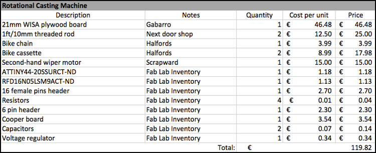
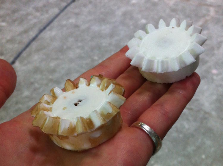
At the most pragmatic level, the success of my project will be based on its mechanical properties, i.e. if it can provide a rotational movement on two axes that would make possible the casting of a shallow molded piece. Yet – more generally – I also want to evaluate the success of my project on its potential to be reappropriated and used by various fab lab sites around the world for their own use. My objective would then be to make a piece that can easily be brought together using methods that we have reviewed throughout the term, as well as cheap, second-hand pieces that can be readily found anywhere. The size and characteristics of these last-mentioned pieces might indeed vary depending on where they are brought, but I aim at developing a design that could easily be adapted to these small variations, if someone somewhere was interested in making another iteration of it for its own fab lab.
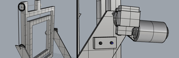
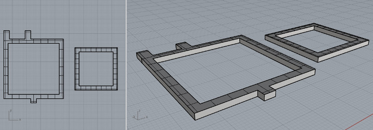
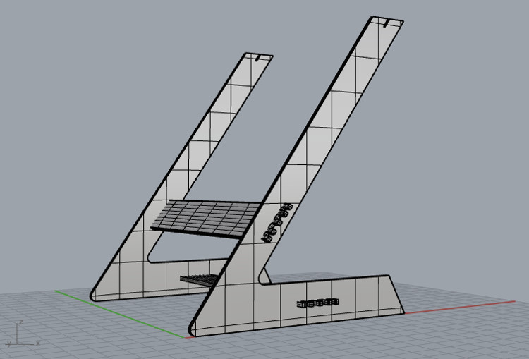
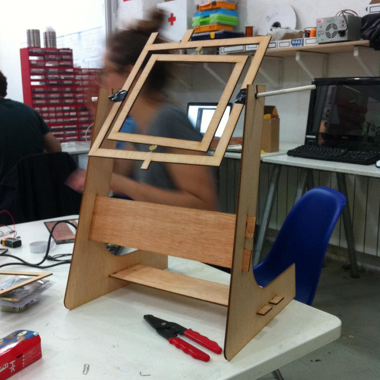
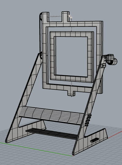
To start on that track, I spent the week working on my design, i.e. making 2D and 3D drawings of the rotocaster, and making a small-scale version of it. To do so, I reduced and adapted my drawings for a plywood sheet of 3mm and laser-cut it – the proportions were fine, but this first prototype made me realized that I had made some measurement mistakes, so I will be able to resolve these issues before milling the actual thing.
Nota bene: to make the 3D model of my project, I downloaded and used some pre-designed pieces from grabCAS – the chainrings, the wiper motors, the switch and the potentiometer, to be more precise. You can find all these models on grabCAD, or download them here. The model itself can be downloaded here.
See below for all the details/for each step.
- Week: 15
- Subject: Applications and Implications
- Tools: Rhino
- Objective: Propose a final project that integrates the range of units covered
- Files: Click here