INPUT

In this assignment I had to make the FabISP in-circuit programmer.

LESSON >>video recording - web

PROCESS


>>> PREPARING MILLING


DOWNLOAD THE BOARD FILES:

traces (mill using the fab modules and a 1/64" bit) and

interior (mill using the fab modules and a 1/32" bit).


CHEKING AND CHANGING THE CORRECT MILL
For traces: mill using the fab modules and a 1/64" bit).
For interior: mill using the fab modules and a 1/32" bit).
OPENNING FAB MODULES TO USE THE MILLING
Start your computer in UBUNTU and open terminal: CTRL+ALT+T.
Write: sudo bash (+enter)
Write password (if it exists)
Write: fab (+enter)
In the new interface choose: Format: image(png) - Process: Roland MDX-20 mill (.rml) and make_png_rml
>>> MILLING CIRCUIT BOARD
MILLING Circuit Board Traces
Load the correct png that you downloaded before.
Choose mill traces (1/64)
View in segments mode
Paremeters: (1) offsets - (0.9) error - (-0.1) z. You can change the offsets value is you need a better work but it will take more time. You can put (-1) offets to fill.
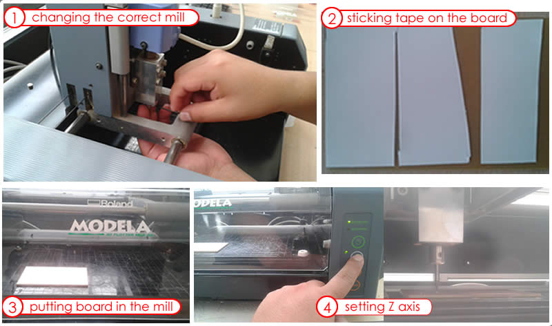
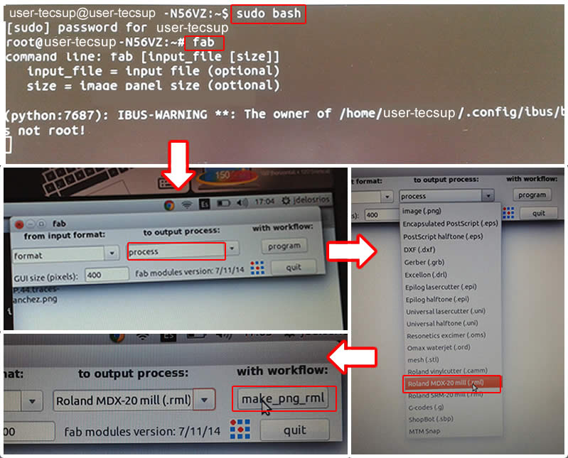
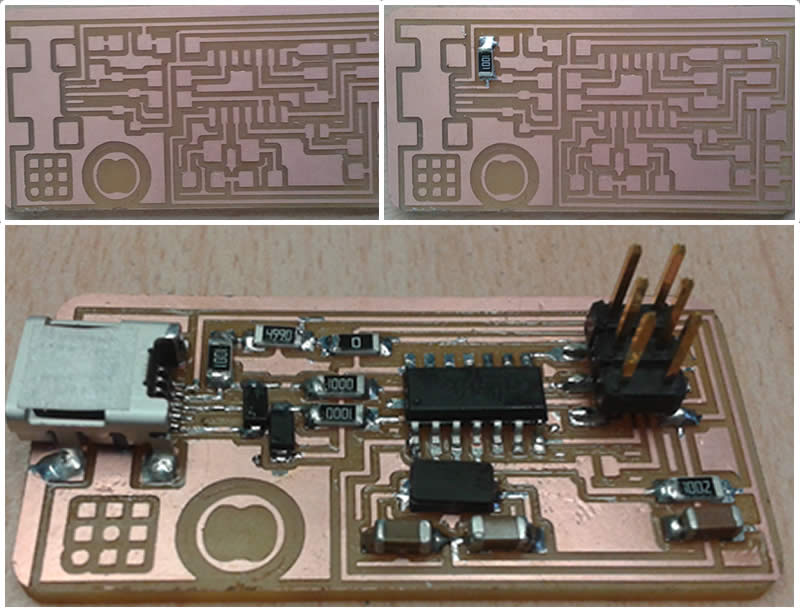
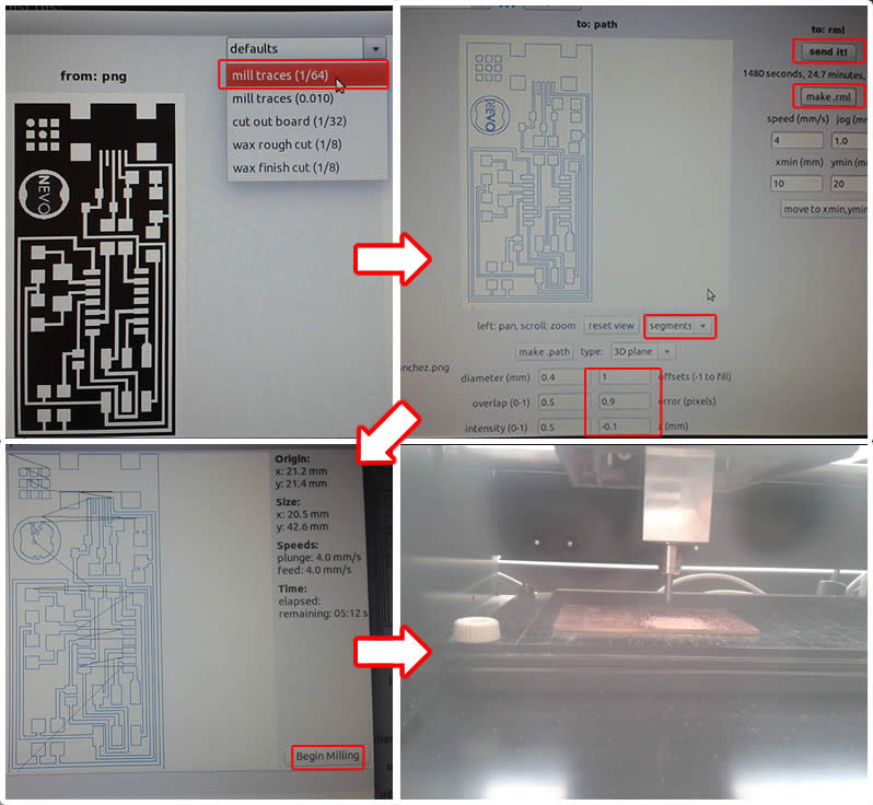
MILLING Circuit Board Interior
Do not forget to change to the mill (1/32)
Load the correct png that you downloaded before.
Choose cut out board (1/32)
View in segments mode
Paremeters: (1) offsets - (0.9) error - (0) top z - (-1.65) bot z.
MILLED FabISP BOARD
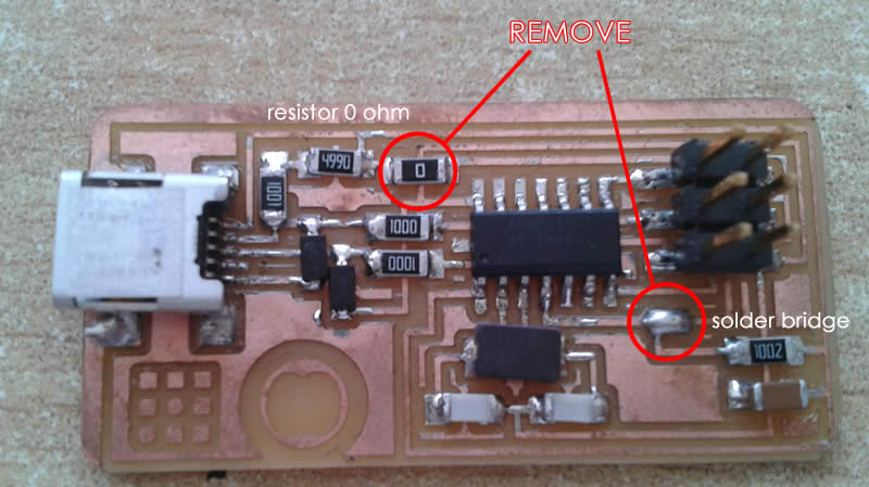
>>> SOLDERING COMPONENTS
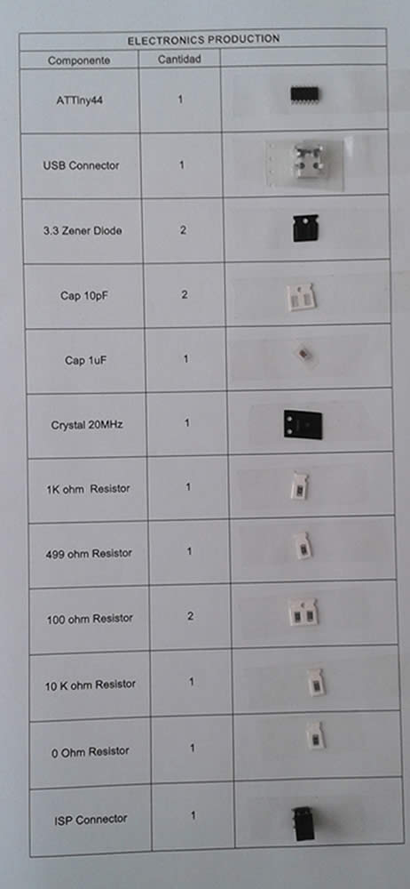
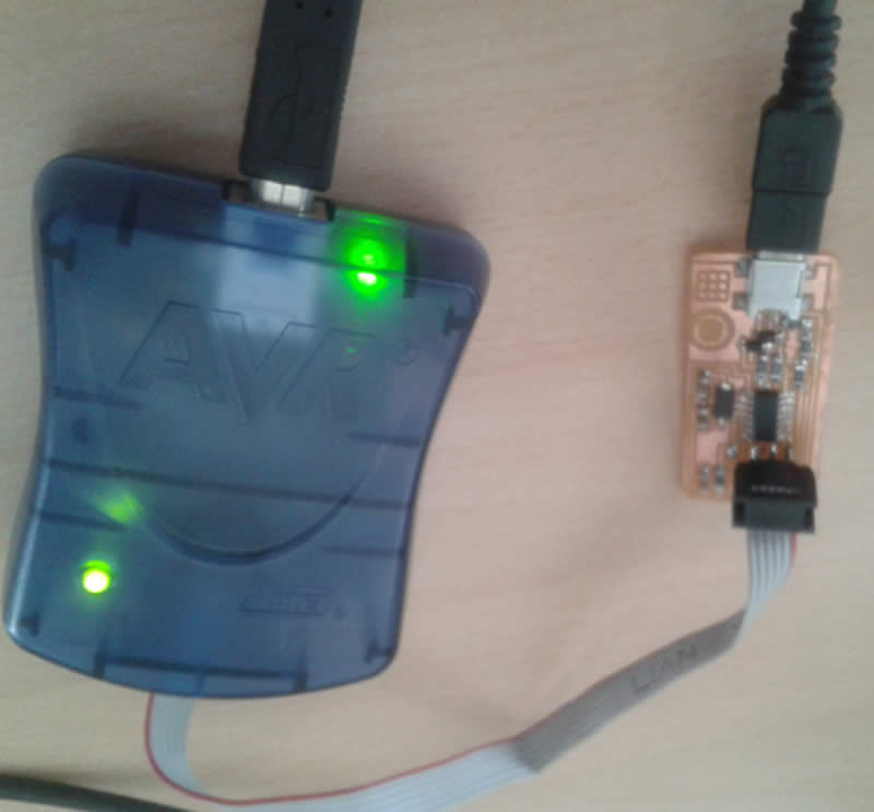


DOWNLOAD:

Download the FabISP labeled board diagram so that you can see what components you need to and where to place them on the board.

Solder the components to the board using a soldering iron and solder (or solder paste and then baking.)


ELECTRONIC COMPONENTS


Mini USB Header (J2 USB)
Solder the mini USB header first. This is the most difficult part and if you are going to destroy the board, you are going to do it here.
Solder with a blob, then wick solder away with desoldering braid.

Microcontroller (IC1 t44)
Solder the attiny44a chip second.
There is a little circle on the chip (view diagram below) that should be facing to the top left if your board is oriented in the same direction as Neil's diagram.
Datasheet for the attiny44.


Crystal ("20 MHz")
Tin the pads first, then place the component on top.
Hold component down with tweezers, the reflow solder at either end.
NOTE: crystals do not have polarity, orientation does not matter.

Diodes
Diodes have polarity the "C" or cathode end is marked with a tiny line.
Place the side with the line on it over the "C" side pad in the diagram.
You may need a magnifing glass.
NOTE: it is helpful to solder the 1K resistor first, otherwise it is hard to get to after you have soldered the diodes.

Resistors ("R")
Here is a handy SMD (surface mount) resistor code calculator.
NOTE: resistors do not have polarity, orientation does not matter.
R1 == 1K ohm == 1001
R2 == 499 ohm == 4990
R3, R4 == 100 ohm == 1000
R5 == 10K ohm == 1002


Capacitors ("C")
Capacitors are not marked, be careful not to mix them up.
NOTE: capacitors do not have polarity, orientation does not matter.
C1 == 1uf unmarked
C2 == 10pf unmarked
C3 == 10pf unmarked

Jumpers (SJ1 and SJ2)
These components are solder jumpers.
SJ1 can be bridged with solder.
Put a 0 ohm resistor over SJ2 on this board.

6 pin programming header (J1 ISP)
Orientation does not matter.

TIME TO SOLDER
>>> TESTING CONECTION
"Smoke Test"
Plug the FabISP into your computer via the mini USB cable.

-If you get an error message from your computer that the board is drawing too much power and that the computer is shutting down the USB port.
-You have a short somewhere on your board. See (Troubleshooting Short Circuits).

If you do not recieve any messges, proceed to "Install the necessary software for AVR programming."

Troubleshooting Short Circuits:

1.- First, do a visual inspection of the board and reflow any solder joints that look cold (not shiny and smooth).

2.- Then, get out your multimeter and check all the connections to make sure that:
- power and ground are not connected.
- there is not a short on the power line.

3.- Common problem areas on the FabISP are:
- the pins on the 6-pin programming header are connected to each other.
- the tiny pins on the front of the mini USB header are connected to each other.
- none of these pins should be connected.
- use your meter to determine which pins are connected.
- use flux and desoldering braid to remove the excess solder and disconnect the pins.


>>> PREPARING TO PROGRAM
INSTALL NECESSARY SOFTWARE TO AVR PROGRAMMING

For the electronics units in the Fab Academy, you will need:

1.- Avrdude (for programming AVR microcontrollers)
2.- GCC (to compile C code)

In my case I used UBUNTU, but if you wish to program in other Operating System visit this tutorial

Ubuntu Software Install

Get and install avrdude / GCC software and dependencies:>
Open Terminal and type:
sudo apt-get install flex byacc bison gcc libusb-dev avrdude>

Then type:
sudo apt-get install gcc-avr

- type "y" when asked to do so by your system

Then type:
sudo apt-get install avr-libc 

Then type (may already be installed):
sudo apt-get install libc6-dev

Download and Unzip the Firmware:
Move to the desktop

cd ~/Desktop

Download the firmware from the Fab Academy Electronics Production page.

wget http://academy.cba.mit.edu/classes/embedded_programming/firmware.zip

Unzip the firmware

unzip firmware.zip


POWER THE FABISP BOARD

The board needs power:
* Make sure that the mini USB connector for the FabISP you are trying to program is plugged into your computer.
* AND that a separate pogramer is plugged in to the 6-pin programming header. (this could be another working FabISP or the ATAVRISP2, a USBtiny, an AVR Dragon, etc.)

Helpful ATAVRISP2 Programmer Light Indicator Messages

If you are using the ATAVRISP2 programmer only. If you connect the programmer to the 6-pin programming header on your FabISP board and you get:

* Green Light: means that the header is soldered correctly, the board is getting power.
* Yellow Light: means that the board is getting power, but most likely the 6-pin programming header is not soldered correctly (re-flow your solder joints / check for cold joints, check for shorts).
* Red Light: means that the board is not getting power - check for shorts.

If you are using another programmer you will need to edit the Makefile.

EDIT THE MAKEFILE

The Makefile is in the firmware directory that you downloaded.

Open the Makefile. Go to the line that says:
#AVRDUDE = avrdude -c usbtiny -p $(DEVICE) # edit this line for your programmer
AVRDUDE = avrdude -c avrisp2 -P usb -p $(DEVICE) # edit this line for your programmer

- If using the USBtiny programmer or another FabISP
- Remove the "#" in front of the line with "usbtiny" in it
- Add a "#" to beginning the line with the "avrisp2" in it to comment it out.
- save the Makefile

OUTPUT


>>> PROGRAMMING MY FABISP
Navigate to the directory where you saved the FabISP firmware. If you followed the instructions above, this will be the desktop.

Open your terminal / command line interface and move to the firmware directory.
Ubuntu / Windows type:

cd Desktop/firmware

Next you need to compile the firmware.
Type:

make clean

If you are successful - you will see this response from the system:
henrysanchez@superH:~/Desktop/firmware$ make clean
rm -f main.hex main.lst main.obj main.cof main.list main.map main.eep.hex 
main.elf *.o usbdrv/*.o main.s usbdrv/oddebug.s usbdrv/usbdrv.s
            

Type:
make hex

If you are successful - you will see this response from the system:
henrysanchez@superH:~/Desktop/firmware$ make hex
avr-gcc -Wall -Os -DF_CPU=20000000	 -Iusbdrv -I. -DDEBUG_LEVEL=0 
-mmcu=attiny44 -c usbdrv/usbdrv.c -o usbdrv/usbdrv.o
avr-gcc -Wall -Os -DF_CPU=20000000	 -Iusbdrv -I. -DDEBUG_LEVEL=0 
-mmcu=attiny44 -x assembler-with-cpp -c usbdrv/usbdrvasm.S -o usbdrv/usbdrvasm.o
avr-gcc -Wall -Os -DF_CPU=20000000	 -Iusbdrv -I. -DDEBUG_LEVEL=0 
-mmcu=attiny44 -c usbdrv/oddebug.c -o usbdrv/oddebug.o
avr-gcc -Wall -Os -DF_CPU=20000000	 -Iusbdrv -I. -DDEBUG_LEVEL=0 
-mmcu=attiny44 -c main.c -o main.o
avr-gcc -Wall -Os -DF_CPU=20000000	 -Iusbdrv -I. -DDEBUG_LEVEL=0 
-mmcu=attiny44 -o main.elf usbdrv/usbdrv.o usbdrv/usbdrvasm.o usbdrv/oddebug.o 
main.o
rm -f main.hex main.eep.hex
avr-objcopy -j .text -j .data -O ihex main.elf main.hex
avr-size main.hex
   text	   data	    bss	    dec	    hex	filename
      0	   2020	      0	   2020	    7e4	main.hex


Next, you need to set the fuses so your board will use the external clock (crystal)
Type:
sudo make fuse

If you are successful - you will see the following response from the system:
henrysanchez@superH:~/Desktop/firmware$ sudo make fuse
avrdude -c usbtiny -p attiny44  -U hfuse:w:0xDF:m -U lfuse:w:0xFF:m

avrdude: AVR device initialized and ready to accept instructions

Reading | ################################################## | 100% 0.01s

avrdude: Device signature = 0x1e9207
avrdude: reading input file "0xDF"
avrdude: writing hfuse (1 bytes):

Writing | ################################################## | 100% 0.00s

avrdude: 1 bytes of hfuse written
avrdude: verifying hfuse memory against 0xDF:
avrdude: load data hfuse data from input file 0xDF:
avrdude: input file 0xDF contains 1 bytes
avrdude: reading on-chip hfuse data:

Reading | ################################################## | 100% 0.00s

avrdude: verifying ...
avrdude: 1 bytes of hfuse verified
avrdude: reading input file "0xFF"
avrdude: writing lfuse (1 bytes):

Writing | ################################################## | 100% 0.01s

avrdude: 1 bytes of lfuse written
avrdude: verifying lfuse memory against 0xFF:
avrdude: load data lfuse data from input file 0xFF:
avrdude: input file 0xFF contains 1 bytes
avrdude: reading on-chip lfuse data:

Reading | ################################################## | 100% 0.00s

avrdude: verifying ...
avrdude: 1 bytes of lfuse verified

avrdude: safemode: Fuses OK

avrdude done.  Thank you.


Next you want to program the board to be an ISP.
Then type:
sudo make program

If you are successful - you will see the following response from the system.
henrysanchez@superH:~/Desktop/firmware$ sudo make program
[sudo] password for henrysanchez: 
avrdude -c usbtiny -p attiny44  -U flash:w:main.hex:i

avrdude: AVR device initialized and ready to accept instructions

Reading | ################################################## | 100% 0.01s

avrdude: Device signature = 0x1e9207
avrdude: NOTE: FLASH memory has been specified, an erase cycle will be performed
         To disable this feature, specify the -D option.
avrdude: erasing chip
avrdude: reading input file "main.hex"
avrdude: writing flash (2020 bytes):

Writing | ################################################## | 100% 5.68s


avrdude: 2020 bytes of flash written
avrdude: verifying flash memory against main.hex:
avrdude: load data flash data from input file main.hex:
avrdude: input file main.hex contains 2020 bytes
avrdude: reading on-chip flash data:

Reading | ################################################## | 100% 3.36s


avrdude: verifying ...
avrdude: 2020 bytes of flash verified

avrdude: safemode: Fuses OK

avrdude done.  Thank you.

avrdude -c usbtiny -p attiny44  -U hfuse:w:0xDF:m -U lfuse:w:0xFF:m

avrdude: AVR device initialized and ready to accept instructions

Reading | ################################################## | 100% 0.01s

avrdude: Device signature = 0x1e9207
avrdude: reading input file "0xDF"
avrdude: writing hfuse (1 bytes):

Writing | ################################################## | 100% 0.00s

avrdude: 1 bytes of hfuse written
avrdude: verifying hfuse memory against 0xDF:
avrdude: load data hfuse data from input file 0xDF:
avrdude: input file 0xDF contains 1 bytes
avrdude: reading on-chip hfuse data:

Reading | ################################################## | 100% 0.00s

avrdude: verifying ...
avrdude: 1 bytes of hfuse verified
avrdude: reading input file "0xFF"
avrdude: writing lfuse (1 bytes):

Writing | ################################################## | 100% 0.00s

avrdude: 1 bytes of lfuse written
avrdude: verifying lfuse memory against 0xFF:
avrdude: load data lfuse data from input file 0xFF:
avrdude: input file 0xFF contains 1 bytes
avrdude: reading on-chip lfuse data:

Reading | ################################################## | 100% 0.00s

avrdude: verifying ...
avrdude: 1 bytes of lfuse verified

avrdude: safemode: Fuses OK

avrdude done.  Thank you.


TO VERIFY THAT YOUR ISP IS WORKING CORRECTLY

Type in UBUNTU:
lsusb

If your FabISP has been successfully programmed, you should see a list of the USB devices plugged into your computer. The FabISP will be listed in a line like the following:
Bus 002 Device 004: ID 1781:0c9f Multiple Vendors USBtiny

Note: Ubuntu 10.10 lists the device as something like:
Bus 002 Device 004: ID 1781:0c9f Multiple Vendors


AFTER YOU HAVE PROGRAMMED THE BOARD

Remove the 0 ohm resistor and solder bridge as shown in the picture below. Now you can use it as a programmer to program other boards.


BUILDING A CASE FOR MY PSB


>>> COMMENTS