


Computer Controlled Machining
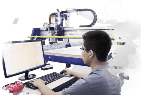
The task this week was to make something big. For this objetive i decided to use The shopbot CNC milling machine. A ShopBot is an do-all tool for cutting, carving, drilling or machining all kinds of things from all kinds of materials. With a ShopBot, you use the included software to design your parts on your personal computer, then, like a robot, the computer controls the cutter to precisely cut your parts. In the past, tools like ShopBots were strictly industrial tools and were referred to in factories as CNC (for Computer Numeric Control) tools. Now, the types of tools that create things by cutting material away or building up material in layers to create an object are called digital fabrication tools, and ShopBot's innovations have made them affordable for individuals and small shops
A. The shopbot CNC milling
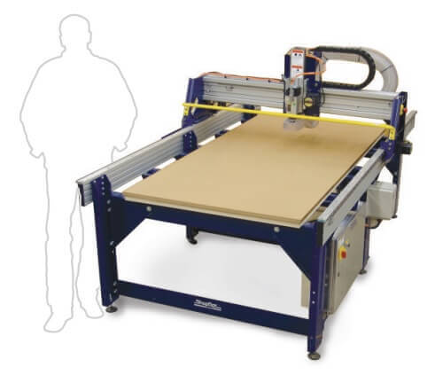
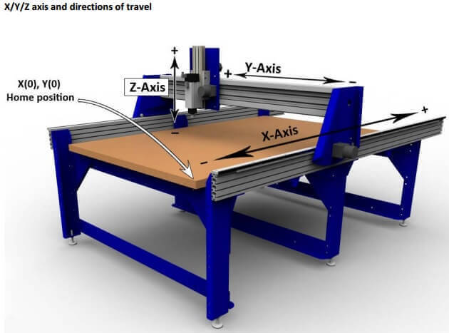
A ShopBot is like a large plotter that moves pens around the surface (in X and Y axes) to create a drawing. Only a ShopBot moves a cutter around a big table (X and Y axes) and moves it up and down as well (Z axis) allowing it to make 3D movements and cut all sorts of shapes. The cutter looks like a drill bit and is spun by a motor called a router or spindle. Unlike a drill bit, a router bit is designed to cut from the sides as well as the tip. By precisely moving the cutter through material, a ShopBot CNC tool can create virtually any pattern or shape and will do it in materials such as wood, plastic, foam, aluminum and many composites.
B. Feeds and Speeds and Chip Load Calculator
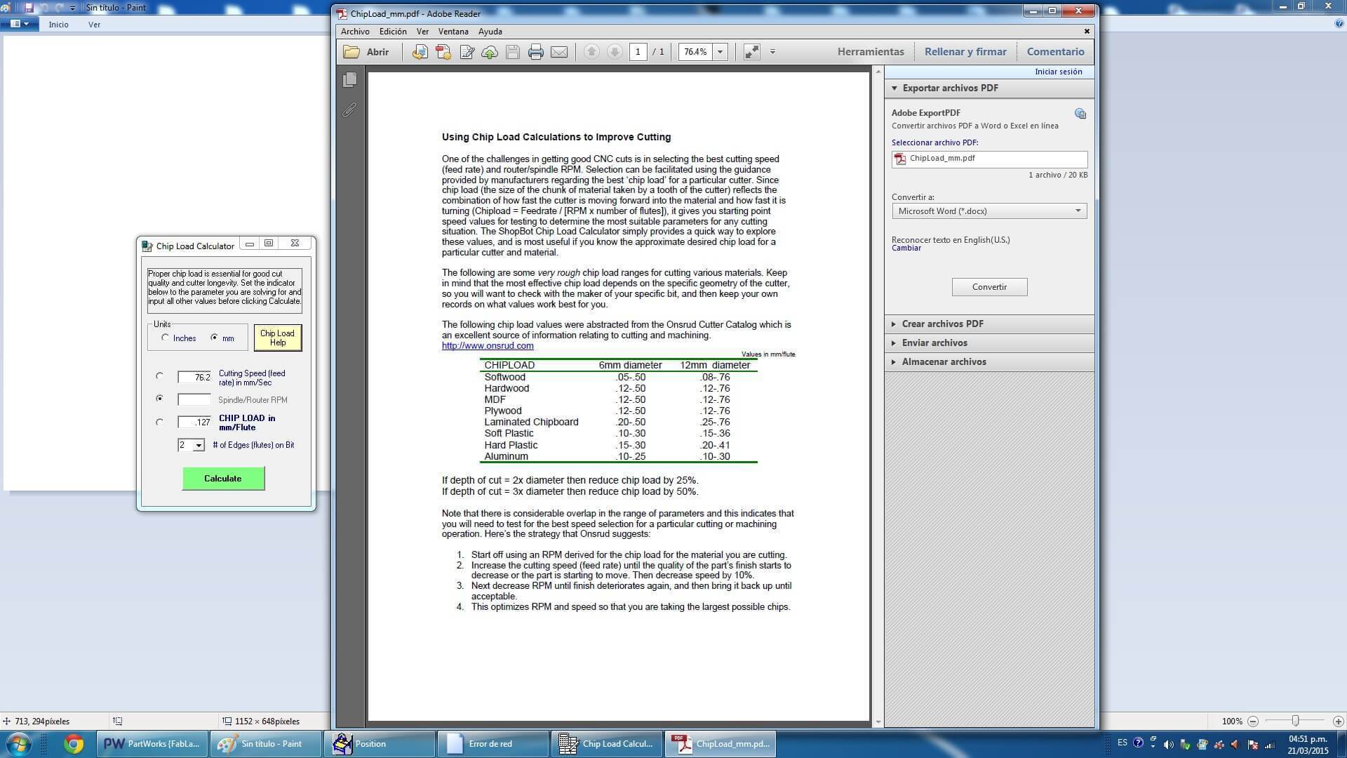
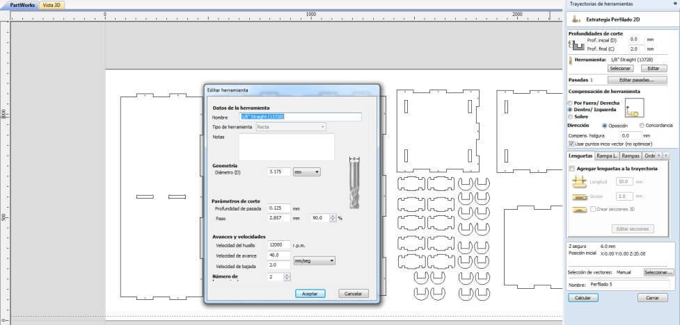
One of the challenges in getting good CNC cuts is in selecting the best cutting speed (feed rate) and router/spindle RPM (speed of rotation). Feeds and speeds are a critical part of machining and should be fully understood before deviating from recommended settings. Selection can be facilitated using the guidance provided by manufacturers regarding the best chip load for a particular cutter. Chip load is the thickness of the chunk of material taken by a tooth of the cutter. This parameter has a relationship between the combination of how fast the cutter is moving forward into the material and how fast it is turning (Chip load = Feed Rate / [RPM x number of flutes]). This relationship shown in the formula gives you starting point speed values for testing to determine the most suitable parameters for any cutting situation. The ShopBot “Chip Load Calculator” simply provides a quick way to explore these values, and is most useful if you know the approximate desired chip load for a particular cutter and material. The Chip Load Calculator tool helps us to choose the most suitable cutting tool , taking into account the cutting speed , material, and the number of threads that have the cutting tool. If we select to Chip Load Help, will show a picture, which appear materials and possible diameter of the cutter.Notably, the Chip Load Calculator is only an aid, and does not determine or confirm any parameter court.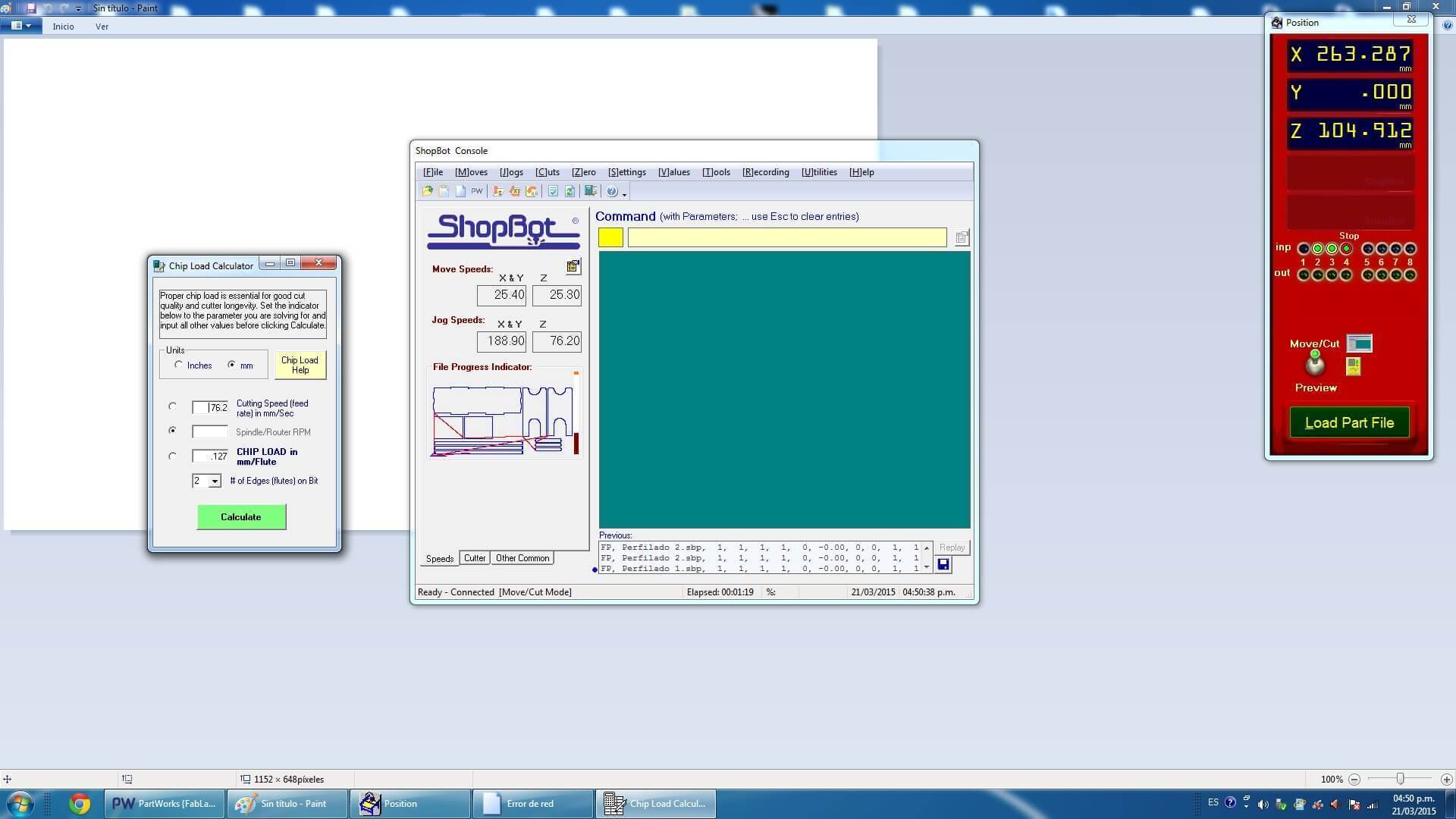
C. Design
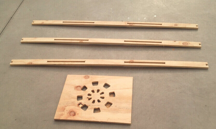
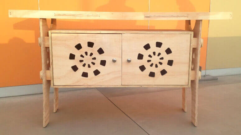
First of all we design a prototipe of a furniture using press fit connections. This model will have many divisions and will be usefull.First of all we design a prototipe of a furniture using press fit connections. This model will have many divisions and will be usefull. Use a reference to Barcelona credenza by Southcone and designed my own version utlizando phenolic boards 15 mm.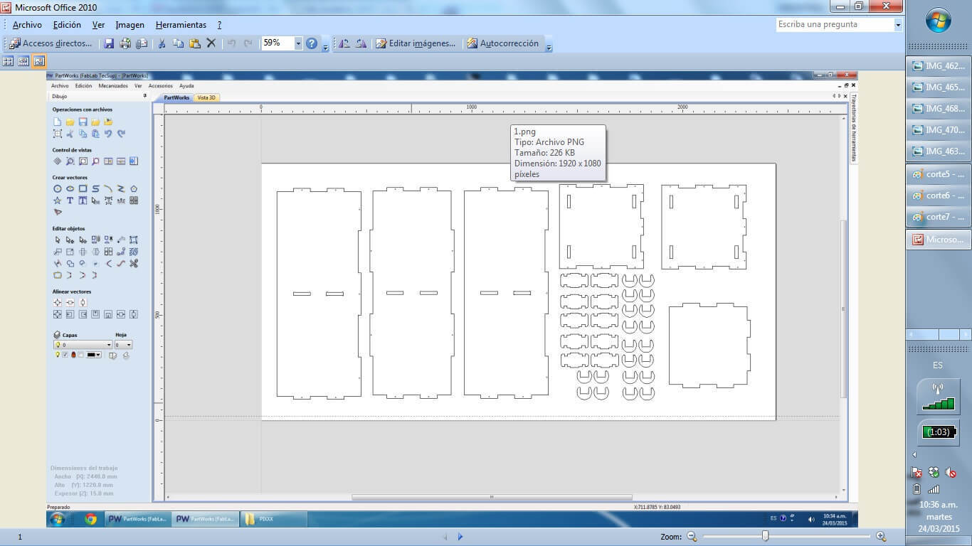
D. Manufacturing
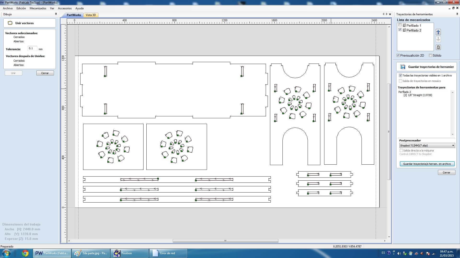
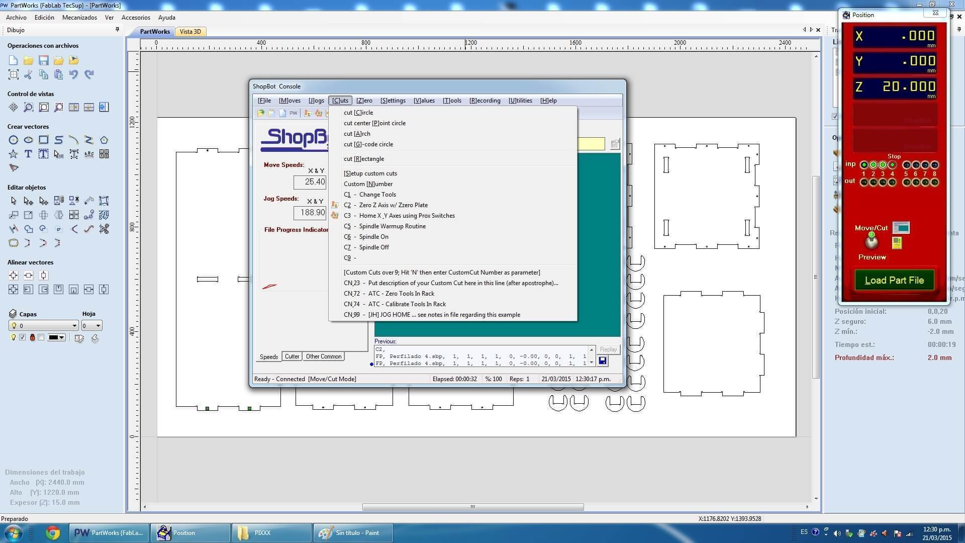
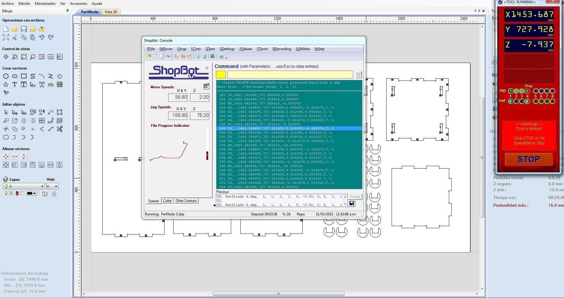
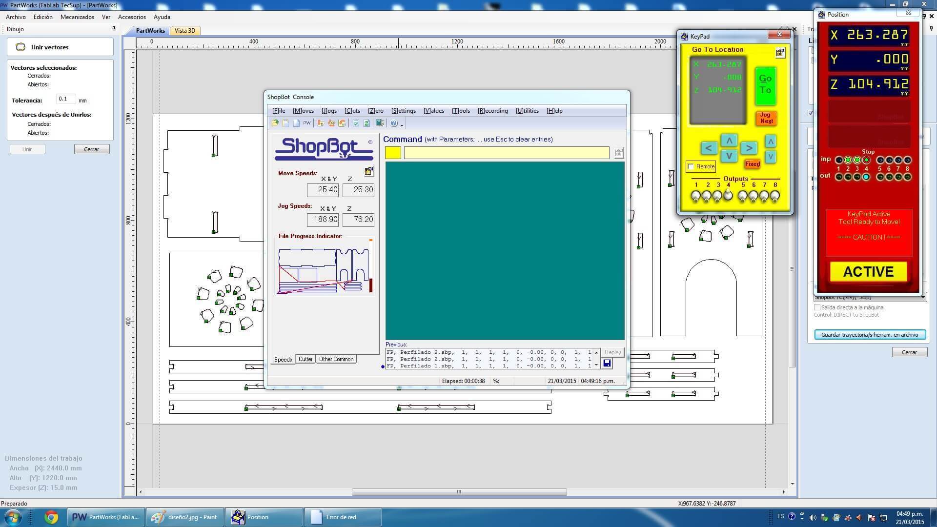
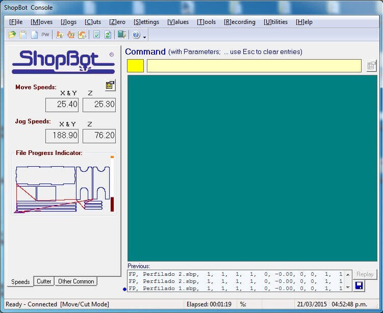
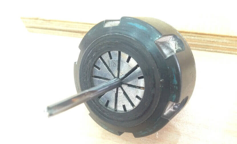
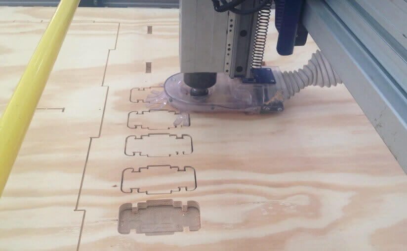
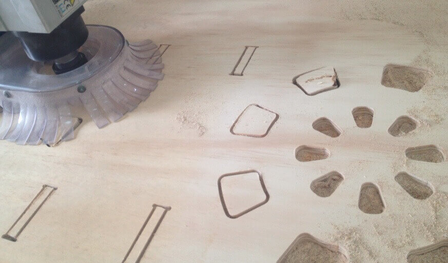
When designing your file, make sure to leave at least an inch around the margins of your material. We will need to screw the material down to the bed of the ShopBot and we do not want the bit on the machine to hit the screws.The cutting procedure is as follows: 0. We respect and follow all safety procedures. 1. According to the design that we must choose the right cutter, according to the resolution of the design, and type of material. 2. We set the chosen material, with screws attached to the plate sacrifice. These screws should be on the edge of the plate, and keep in mind the position of these screws, since if the drill goes through these screws will break and will fragment violently. 3. After fixing the plate material, we use the tool to first calibrate X, and Y. Then also calibrate the Z axis using a metal blade. These options are in the Cut tab, XY Calibrate, Calibrate and Z. 4. We import furniture design at Software Partworks and select the vectors to be cut. We keep these vectors selected as .sbt files and then import them. Preferably it is saved in 2 files of court. In the first inner sections, and the second file in external cuts, so that the plate does not move. 5. Open the ShopBot3 software, and import the file and then send .sbt cut. 6. Once you compile the file and send it, a window that tells us that first we press the green start button, to start to turn the cutter, and once it has reached full speed arises, then we click on the OK button to start cutting. 7. Then send the file to cut almost immediately turn on the extractor cut waste. Note. If any problem arises, we press the emergency stop button. Or else you can pause the job by clicking the STOP button, then stop automatically. To resume the job, click Resume, Then Start button, to turn the cutter, and then click OK. Failure to follow these steps in the exact order, it may break the cutter, to either inherit with the cutter motionless.
Downloading link for my archives: Archives
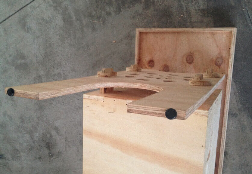
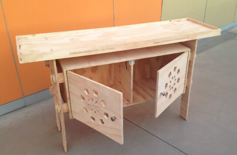
E. Proceed to assemble
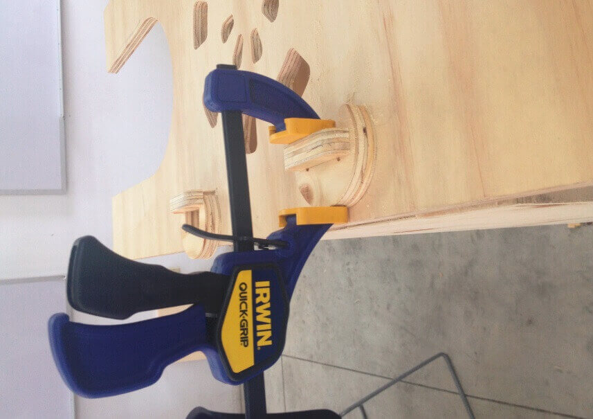
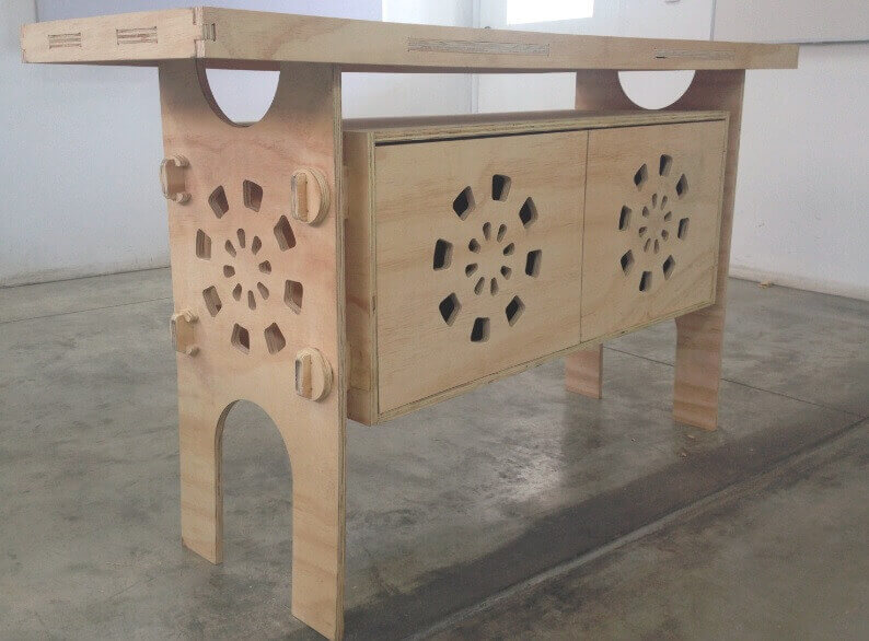
Once the lists parts, we proceed to assemble gradually. We started putting together the central box structure , then continue with press-fit connecting the central box with side studs. To join them used a hammer and grippers , do not use any connector because all parties are part of the structure. Then continue with the assembly of the upper table , and finally leaving the doors. For doors we added some haulers, and magnets for better design and finish. We then present the furniture in various positions.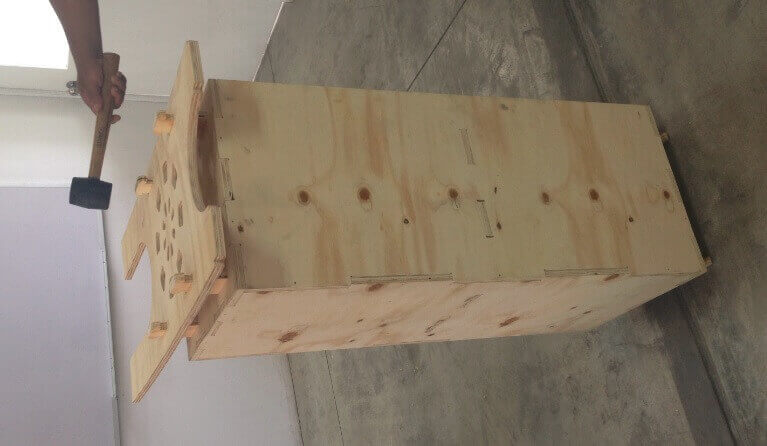
 Enjoy!