Digital fabrication, electronics, rotary axis, automatic tool changer, image processing, open cv, science, technology, networking
"Double sided layer - PCB Milling Machine"
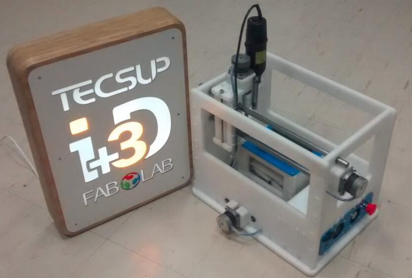
Final Model
A. Target
The project was to develop a CNC milling machine for PCB plates, which mill has the capacity to double-layer plates and a system of automatic exchange of tools. One of the main problems when designing an electronic board is the distribution of the components and routing their paths, this is easily solved by designing a double sided PCB. However in this process both sides must be aligned, otherwise the holes and vias in each layer won't match this usually happens when turning the boards manually. I decided to build a machine that can make double side PCB boards easier, as current machines usually finish one side of the board first and then the user swaps the board side being careful to keep the pcb same location. My project seek to reduce or even eliminate the time spent changing the side of the board.
B. Documentation during development, demand- vs supply-side time management, spiral development
To do this we will design and build a "Double sided layer - PCB Machine" This machine can perform drilling, milling and routing any PCB for a maximum area of 10x10cm. Additionally it will include a system that will rotate the boards for routing the back copper layer. This prototype will also have an automatic tool changer
B.1 Scope
The machine is capable of milling, cutting and drilling PCB plates, The PBC optimal plate format will be able to work the is 100 mm wide and 100 to 130 mm long
The maximum number of tools you can carry in exchanger for the automatic transmission is a 4 milling cutter.
B.2 General Features
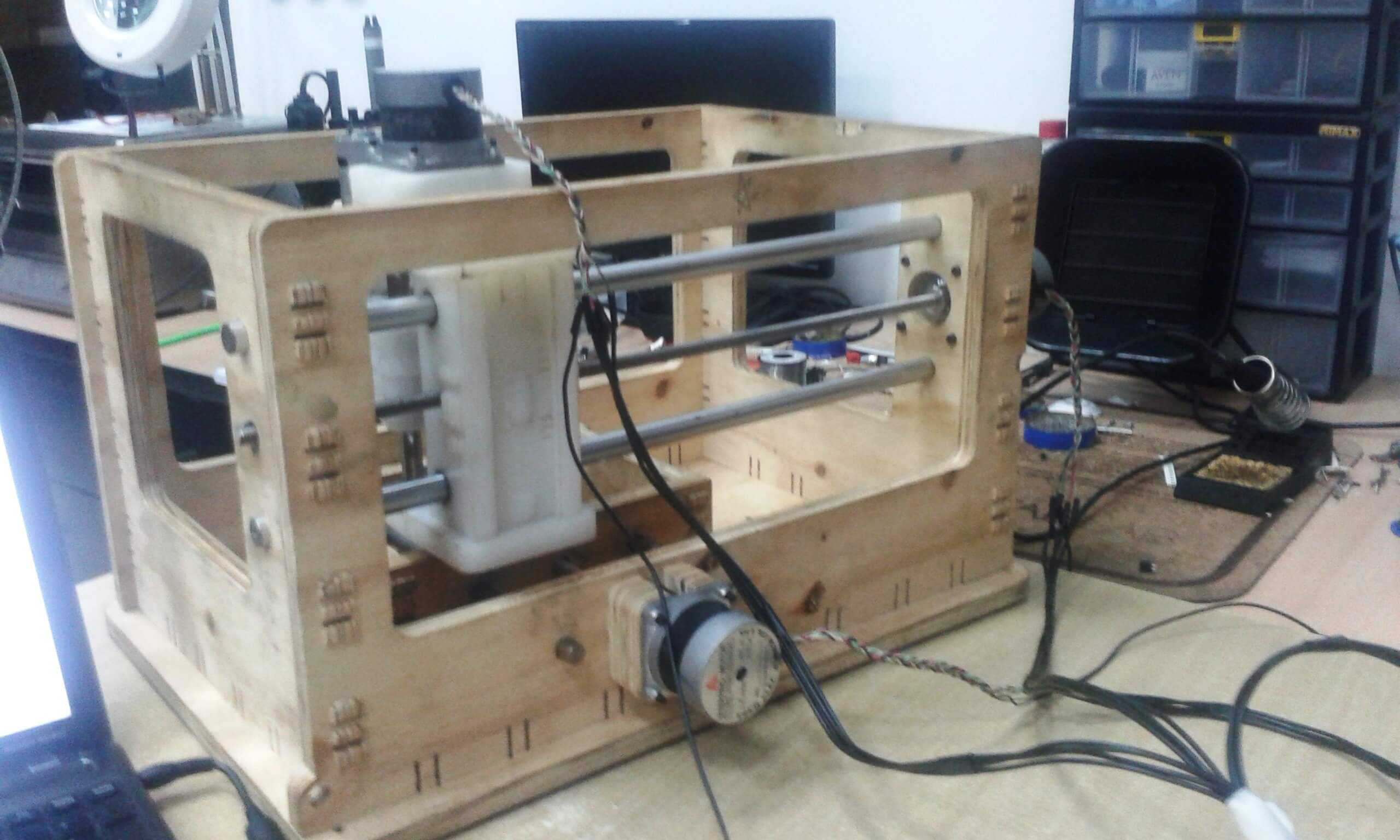
I left the base and form of the MTM design fabLAB, I changed of the dimensions and shapes as needed and new goals. The surface dimensions of the machine are 512mm front, 335mm and 425mm background high.
The milling drill has 240W of power, the working voltage is 220V and maximum working current is 1.5 amps. Have been implemented six axes of movement: coordinates X, Y coordinates, Z coordinates axis to flip and shift PCB support base.
The movement of all axes of the machine is achieved by activating stepper motors 1.8 °, 24 volts and 0.21 amps.
The base material used for the majority of parts is High Density Polyethylene 15mm thick.
It has also been used gauged steel bars for holding and guiding the movement axes and duralumin holder elements for milling cutter and milling cutter exchange base.
B.3 Parts
Case
The main housing consists of 6 plates with press fit joint, which form the foundation and walls on which the axes, rods and brackets for movement in the X and Y coordinates will be mounted, the intermediate base also support the exchange system milling cutter and isolate a space for power and control connections.
6-piece assembly with union press fit on this basis the displacement in the X coordinates is done and has a maximum travel of 370 mm, also on this basis the head is mounted, the guides, the auger and motor steps governs the displacement in the coordinate Z. In such assembly have been placed 4 threaded rods with nuts on the ends which compact the structure and help the accuracy of movement in the X and Z.
Head movement Z coordinates
3-piece assembly design suitable for securing vertical milling drill, the centerpiece of the assembly has a triangular recess accommodating the corresponding nut fixedly, achieving the positive or negative movement with the rotation of the threaded rod coupled the stepper motor that governs this displacement in the Z coordinates, the maximum travel is 100 mm.
Table Y coordinates movement
4 parts assembly joint press fit, box-shaped, with a triangular recess in one of its walls to achieve displacement and a subsystem within the table for the vertical displacement of the support base that stabilizes the PCB before milling work. At the top of the table and is designed housing rotating shaft which causes the turning of the PCB as well as the holes for mounting the stepper motor for this purpose.
Support Base
Two metal axle assembly and a threaded rod coupled to a stepper motor, all mounted within the walls of the Bureau of movement in Y coordinates, and two square bars of high density polyethylene; one fixed and one recess housing by a nut and said positive or negative for the same displacement, the two square bars are interconnected by crossbeams and in the central holes that together form a blade that transforms the horizontal motion of the square bars in vertical movement of the support base. This base should be placed in its lowest position to allow flipping the PCB and then in its highest position to join the board, align and provide stability before milling work.
System for rotating PCB
This system consists of two metal shafts coupled jaws HDPE holding the PCB by prisoners, one of the axes is also coupled to a stepper motor that rotates 180 degrees to allow flip the PCB
Drill Milling
It is a modified regarding the accommodation milling cutter commercial drill, which is designed holder base for milling cutter and milling cutter duralumin holder as well as controlling its on by an electronic board that receives the automatic control on and off.
The milling drill has 240W of power, the working voltage is 220V and maximum working current is 1.5 amps.
Automatic Tool Changer
It is a metal plate with 4 cuts U-shaped allowing clamping horizontally income holder milling cutter, this dish is coupled through gears to a stepper motor It takes on an angular displacement of 90 degrees every move making to alternate the milling cutter position as required by the process
C. Process
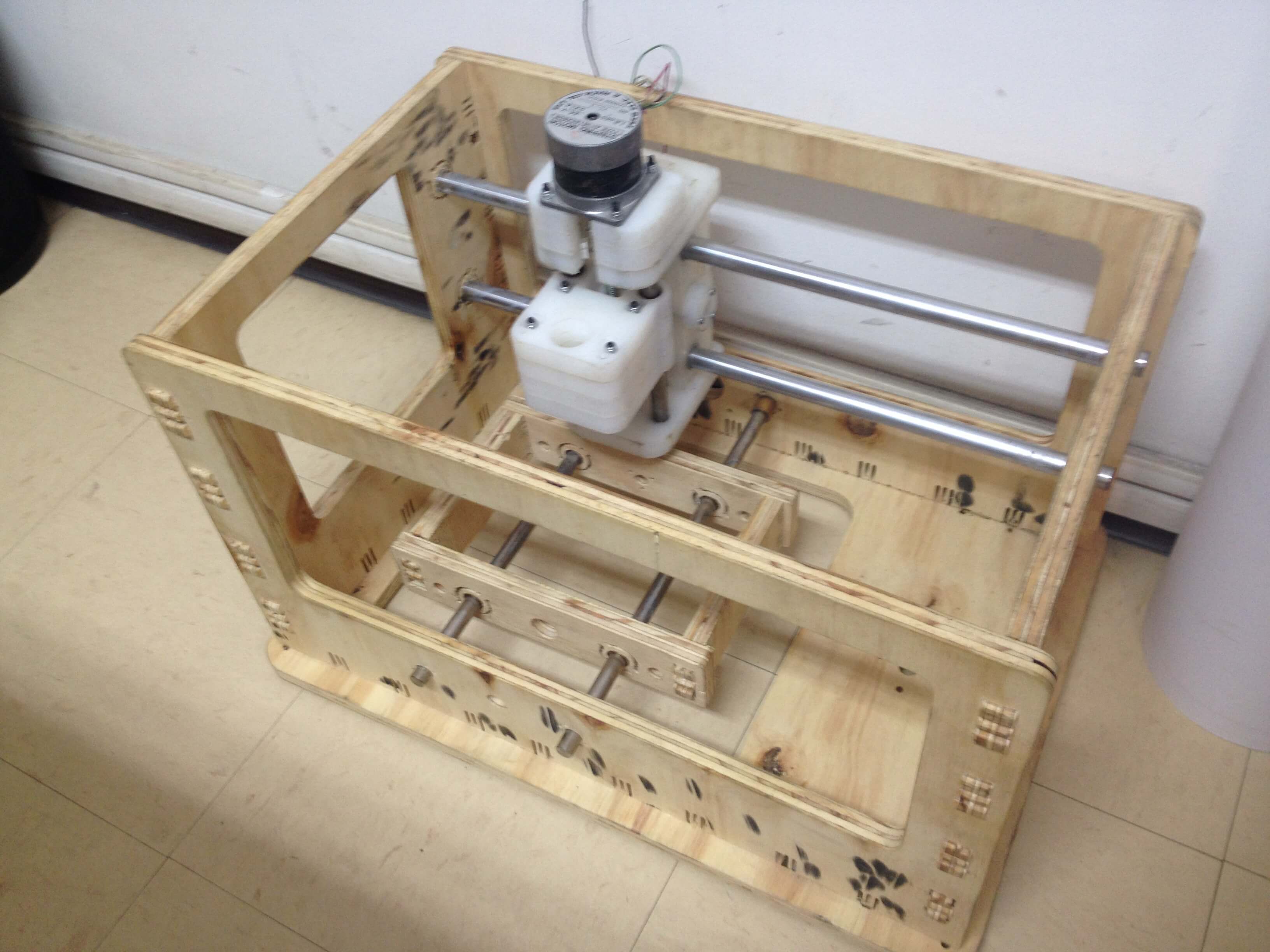
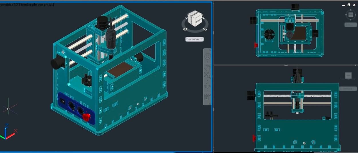
First structure
Close-ups of the machine by modifying the original measurements were made MTM. Including spaces for the location of Disco exchange, considering the shape of the table coordinates movement and stepper motors include two houses on the outer side of said table, along the route increased Z coordinates of head.
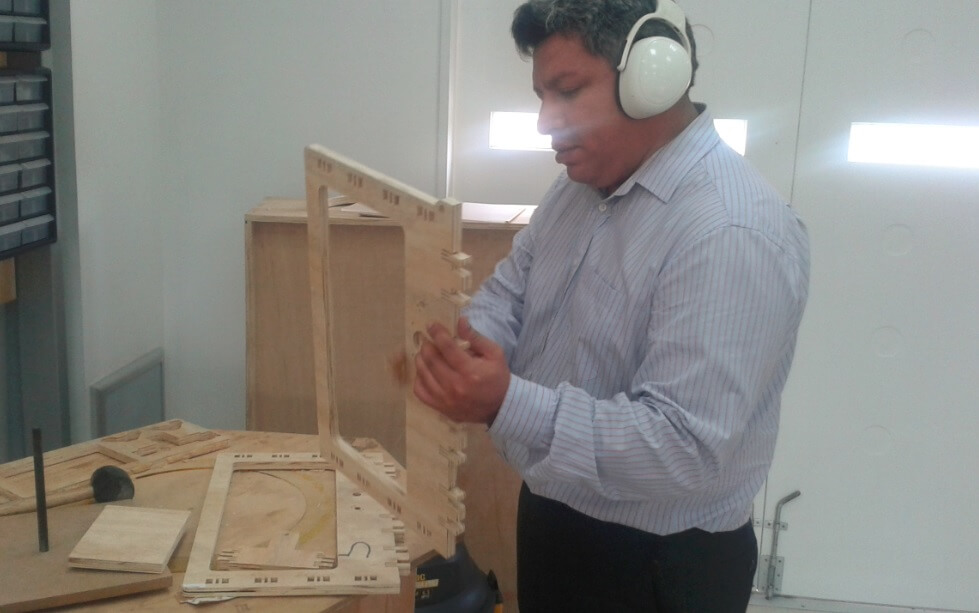
For the first cut 15mm phenolic plywood was used, using 45% of an entire sheet of 1.2mx 2.4m, it was found to perform in the process of reinforced phenolic plywood that has not performed well in the press fit together such that He was used. Yet with some modifications was achieved broken pieces have the structure to mount the parts and the first tests
Was also modified from the original form the head, since there would be no transmission components (engine, pulleys, belts, carries drill axis), support pieces was designed for milling drill would carry itself the basis for the cone holder milling cutter.
Another modification of the original system is that due to the increased weight of the head, by the physical characteristics of milling drill two expansion springs were placed parallel to the axis of displacement in the Z coordinate to reduce the effort developed by the motor steps lift the head.
Motion systems
For all displacement systems you are using the same structure, which consists of a threaded rod, a nut fitted to a part of the portion which is subjected to the movement, which is caused by passage coupled to said nut stepper motor.
It is important to take into account the characteristics of the threaded rod, which is made of stainless steel, diameter 3/8 "and its passage is 16 threads per inch, which is equivalent to a step of 1.5875 mm per revolution.
To convert the rotary motion of the stepper motor to linear motion component of the machine must take into account a basic characteristic of the motor, which is its extent in the case of the engine used is 1.8 ° per step, by plate, which amounts to 200 steps per revolution.
Because the motor and threaded rod are coupled directly, we can infer the following: 1 motor revolution is equivalent to 200 steps and also equals 1.5875 mm linear displacement. By simple rule of thumb to move 1mm 125 984 steps or a factor that value according to the micro steps are defined in the physical connection of driver governing every move, a figure that is set when programming the machine are needed.
It is being used as displacement guide for the movements in each coordinate, two calibrated steel bars which are housed in the walls of the machine housing and are safe fastener circlip located on the outside thereof. The characteristics of the bars are as described below:
• For the X axis, which carries a distance of 300 000 t meters and supports an approximate weight of 3 kg, it is determined that the bars have a say to meter 16 000 í meters.
• For the Y axis, which carries a distance of 130 000 t m and supports a weight of 2 kg, it has been determined that the bars have a di meter to 12 000 t meters.
• For the Z axis, which carries a distance of 100 000 t m and supports a weight of 2 kg, it has been determined that the bars have a say to meter 12 000 í meters.
• For the axis of elevation or n support table, which develops a tour of 50 000 t m and supports a weight of 500 grams has been determined that the bars have a di meter to 10 000 t meters.
It has been considered as transmission element linear motion nut 5/8 "accurately housed in a triangular recess which has no option but rotary motion if it moves linearly according to the type of rotation of the threaded rod therethrough. Whereas the guide elements pass through two walls moving component; the nut stayed at the nearest location to the point stepper motor to achieve a more efficient transmission wall.
It was considered brass horns at points of contact with the guide walls of the component that move according to the following detail:
• For the x axis, which has bars 16 000 t m Subway di speakers are 16 x 20 x 15 000 í meters.
• Shaft and having bars 12 000 t m Subway di speakers are 12 x 16 x 15 000 í meters.
• For the z axis, which has bars 12 000 t m Subway di speakers are 12 x 16 x 15 000 í meters.
• For the axis of elevation or support table n q ue has bars 10 000 í meters underground say to speakers measuring 10 x 14 x 15 000 í meters.
Milling cutter exchange system
To achieve the automatic exchange of milling cutter a system is designed on the intermediate base consisting of a stepping motor, gears for transmitting motion, polyethylene three plates for accommodating the vertical shaft supporting plate that guides exchange movement by means of two axial bearing.
Milling cutter change process
Initially the drill is inserted a cylindrical device whose inner wall has a female conical shape, with a degree of development of 1.5 degrees and exchange the disc housed in the grooves takes male cone cutter holder also has different use a degree of development of 1.5 degrees.
To catch a tool of mill, the program will determine which type of cutter is needed and align the appropriate exchange disc position with the axis of displacement of the head in the X, the head will move in the Z coordinates to locate position that allows for above the maximum height of the cone holder milling cutter, then head it will move in the X positive coordinates to match the vertical axis of the cone holder milling cutter and moves in the negative Z coordinates to achieve coupled with precision the housing and the cone exerting a pressure corresponding to a maximum grip. The output now with his head inserted cone will move in negative X coordinates to exit the swap disk slots.
Now the process of exchange of a milling cutter on the other began with the movement of the head in the Z coordinate to achieve the alignment of the swap disk slots and cone holder milling cutter, verify that you have that is not how the slot is aligned mounted with the X, and the head will move in the positive X coordinates to achieve the coupling between the grooves of the cone holder milling cutter and swap disk, hence the movement of the head in the positive Z coordinates peel off the cone of the housing having the main bore and located above its axis allowing it to rotate freely, a disc rotation exchange a new cone located aligned with the axis of the drill and the displacement of the head in the negative Z coordinates achieve precision coupled with the housing and the corresponding cone exerting minimum pressure and maximum grip. The output of the head now with its newly inserted cone will move in negative X coordinates to exit the swap disk slots.
Spinning process PCB board
To perform this process is scaled motion table Y coordinates, that enables mounting therein a displacement system for a support table having the ability to lower to minimum position in Z coordinates and allow the plate PBC make a 180 degree turn freely, and up to a maximum position in the Z coordinate to support the PCB in the milling process.
The PCB is mounted on the holding jaws at their ends, such jaws are subject to the table by two bars housed in respective holes at the top and center of the side walls of the movable table, forming the set ( bars, clamps and PCB) a pivot axis parallel to the axis X of displacement of the head and guided by this is that the process of rotation of the PCB is performed by activating stepper motor which governs its movement. The condition for the spinning process begins plate is that the support table is in its lowest location by activating the stepper motor for this purpose, allowing the plate to rotate freely, and completed the turn, the support table you must climb to its highest location to perform its function of support and the milling of the opposite side of the PCB is ready.
Testing process commercial software for PCB milling squares
Having achieved the basic physical implementation of the machine, we proceeded to perform the tests with commercial software for moving axes and CNC operation, being open source software to download code and even modify the firmware control, including the highlights are:
• GRBL (Windows / Linux)
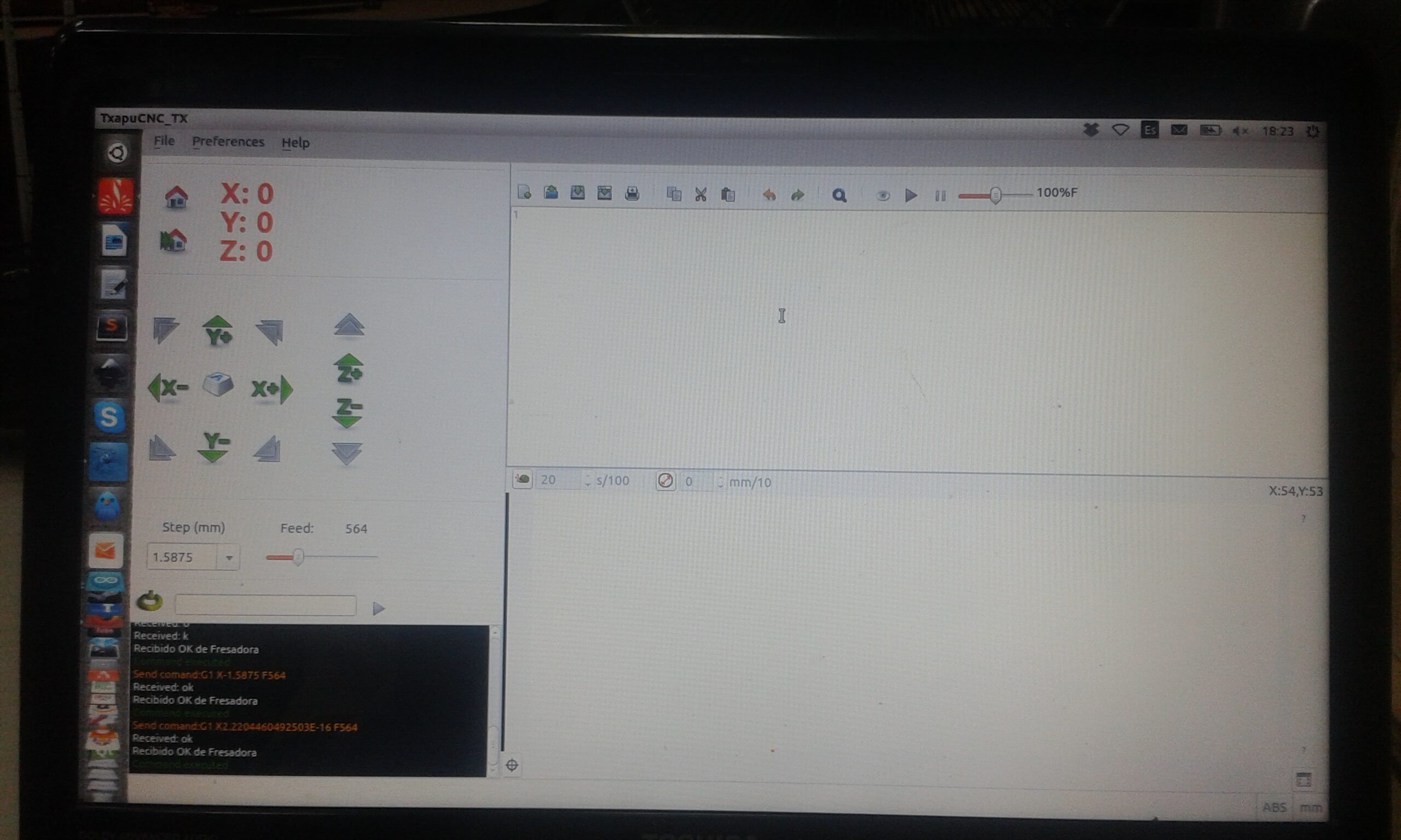
• TxapuCNC (Linux)
First tests with Windows GRBL
GRBL was the first software that we run on the machine, due to its simple process for downloading and installing.
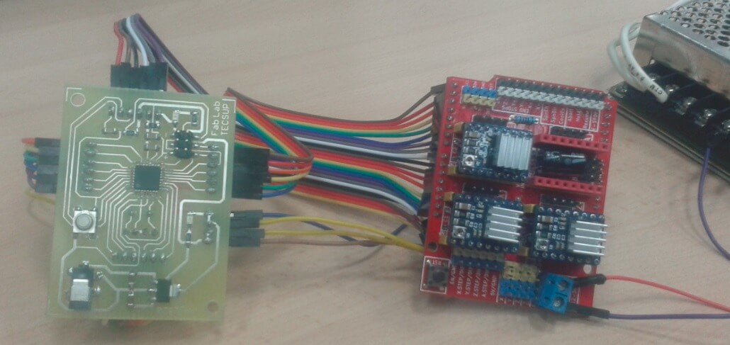
As hardware implemented the following elements:
• Arduino Uno R3 01 piece
• CNC Shield 01 piece
• Driver DRV8825 03 pieces
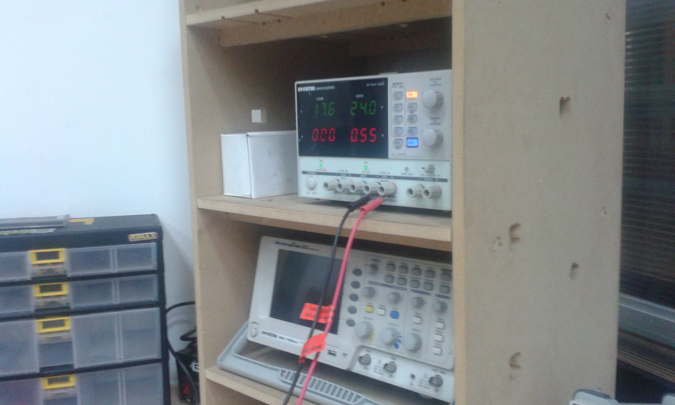
• Source Switch 24 V 10 amp. 01 piece
• Interconnection wiring estimated
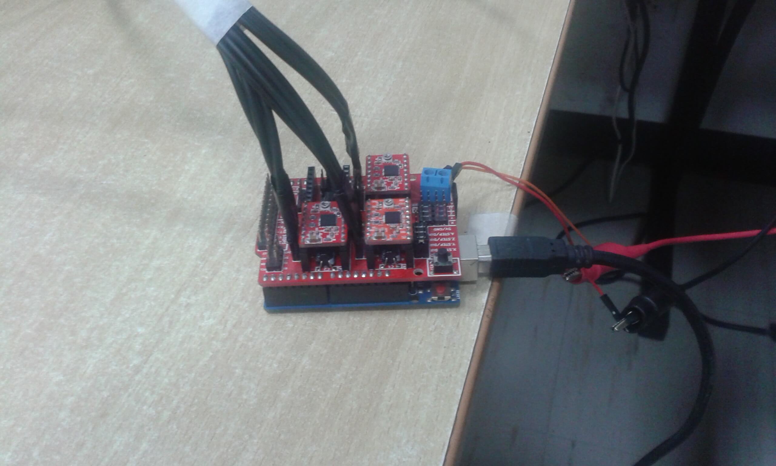
For these first tests we are considering the three coordinates of motion ( X , Y, Z ) , we wired the three stepper motors that govern every move of the coordinates
The Arduino Uno and CNC Shield plates are designed to overlap, the DRV8825 drivers also have a connection module in the shield plate reserved for each coordinate axis
CNC Shield provides the interconnection between the drivers and the Arduino Uno, also has outputs for peripheral and complementary elements of the machine (emergency stop, limit switches, buttons Start, reset, etc.) other than the input terminals of forward voltage according to engine capacity step (in this case 24 volts)
As software GRBL for Windows must first download a firmware, grbl_v0_9i_atmega328p_16mhz_115200.hex by a Xloader to the Arduino, a process that began detecting the port that the Arduino Uno is connected, it should also regulate the baud rate. Recommended in this case is 115200 units of signal per second.
It also has to download the UniversalGcodeSender interface and this interface , recognize the communication port , set the baud rate and open communication.
UniversalGcodeSender gives you the ability to configure certain values through special commands
• $ 1 = 255 step idle delay, msec
• $ 100 = 125 984 X step / mm
• $ 101 = 125,984 Y step / mm
• $ 102 = 125 984 Z step / mm
• $ 110 = 100,000 X max rate, mm / min
• $ 111 = 100.000 Y max rate, mm / min
• $ 112 = 100,000 Z max rate, mm / min
With those data entered obtain accurate physical results according to the codes that we generate from a png image
Txapuzas first tests with Linux
For tests with Linux txapuzas and it remained the same hardware used GRBL, and observed that the order of the pins was not similar communication between GRBL and Txapuzas
Order of original communication pin Txapuzas
// Cartesian pins bot
#define X_STEP_PIN 8
#define X_DIR_PIN 9
#define X_MIN_PIN 4
#define X_MAX_PIN 2
// #define X_ENABLE_PIN Pin 15 Analog 1
#define Y_STEP_PIN 10
#define Y_DIR_PIN 11
#define Y_MIN_PIN 3
#define Y_MAX_PIN 5
// #define Y_ENABLE_PIN Pin 15 Analog 1
#define Z_STEP_PIN 12
#define Z_DIR_PIN 13
#define Z_MIN_PIN 7
#define Z_MAX_PIN 6
// #define Z_ENABLE_PIN Pin 15 Analog 1
// #define MOTOR_PIN 19 on / off head (Analog Pin 5)
Order pin Txapuzas communication hardware adapted to l GRBL
// Cartesian pins bot
#define X_STEP_PIN 2
#define X_DIR_PIN 5
#define X_MIN_PIN 9
#define X_MAX_PIN 9
#define X_ENABLE_PIN 8 // Pin Analog 1
#define Y_STEP_PIN 3
#define Y_DIR_PIN 6
#define Y_MIN_PIN 10
#define Y_MAX_PIN 10
#define Y_ENABLE_PIN 8 // Pin Analog 1
#define Z_STEP_PIN 4
#define Z_DIR_PIN 7
#define Z_MIN_PIN 12
#define Z_MAX_PIN 12
#define Z_ENABLE_PIN 8 // Pin Analog 1
// #define MOTOR_PIN 19 on / off head (Analog Pin 5)
Unlike Windows GRBL Txapuzas firmware is open source, and can be edited using the Arduino IDE, hence the definition of the pins are edited according to the above list lines by the same IDE Arduino firmware is up to the plate Arduino Uno.
The interface txapuzas need the Gambas (programming language) to be operational from there runs the interface, setting the port and the corresponding baudaje
In both test runs it was achieved three axes move successfully manually and load G basic codes and test performance.
It was easier to operate the GRBL, flexible in making changes to program
In the txapuzas encounter difficulties with regard to the type of code that receives
Arrangement of elements for electronics
The composition of the elements for electrical / electronic part of the machine remain as noted below;
• Acometida.- cable socket energ y of the (220V monophonic SIC) network and moved to the socket that is attached on the board
• It takes the energy female receiving í to rush and distributed to food or No drill, the power switch, and other rich peripheral element.
• Source Switch, which receives the voltage or 220 volts AC n and converts 24 volts DC to power the CNC Shield and connections for stepper motors.
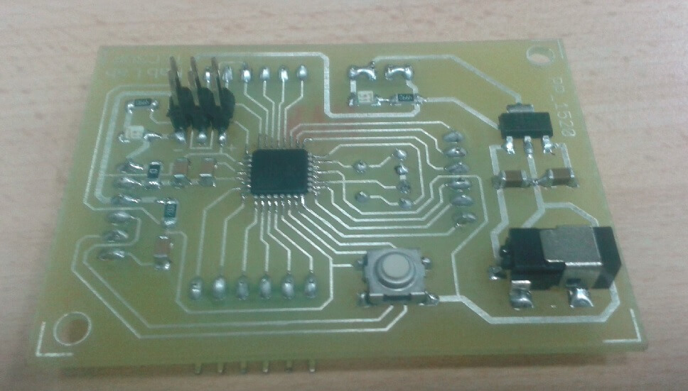
• Fabduino plate receives n communication or computer using the FTDI port v ay it is that you download the firmware and in addition to the s.-C or G and other codes
• CNC plate .- Shield housing plate 8825 drivers for stepper motors
• Drivers Drivers 8825.- steppers they receive the Step and Dir and 4 outputs are directed to the stepper motor
• Microswitch late carrera.- normally open located at the ends of the displacement of the X, Y, Z, table stand, which is it is connected to the plate CNC Shield.
General procedure to upload a file milling
It has considered working in the Linux environment to develop software of the machine, for which it has been possible to run the firmware GRBL as a language of communication, has raised the GRBL two fabduinos, and have been linked to each fabduino a Shield CNC turn DRV8825 three drivers for each Shield. In a fabduino the three main axes X will be monitored, Y, Z. On the other Fabduino the axis of rotation of the plate, the linear movement of the support table and the angular displacement of the disk were controlled exchange.
Downloading link for my archives of fabduino:
File
In the interface it has been made to link the CAD.PY which is open source software, which converts PNG files to their corresponding G code editing options and configuration.
Once loaded the interface and the connection with fabduinos, you must first calibrate the 0 position, for the three axes of movement, to do this we will rely on the purpose of physical career and set up by the appropriate calibration procedure.
After loading the Cad.py the PNG image capture circuit routing, define variables as cutter diameter, work area, maximum height Z, travel speed, among others. Appointing the G code to generate a file, that file is loaded into the interface and basic milling process begins.
Interface
We are using the PyCharm editor for debug and GRBL compilation Interface software, we start with
Firmware GRBL communication burned in the Fabduino, for implementation of the interface in a script in python which had communication account and the correct baud rate of Fabduino ATmega328, establishing communication with the port /dev/ttyACM0 or /dev/ttyACM1 depending on the location of the Port (command in linux $ Ls / dev / tty *), the baud rate of Fabduino is 115200, this was achieved with script communication with Fabduino and drivers stepper motors. We also use the configuration commands the GRBL for orders of movements, the command for the configuration revision is "$$", also used the default commands change steps / mm and the speed of axis commands used were "$ 100 = -", "$ 101 = -" and "$ 102 = -" changing the steps / mm (mm per unit) of Firmware being the X axis, Y axis and Z axis respectively, the "$ 110 = 100", "$ 111 = 100" and "$ 112 = 100" command changing the speed (feedrate) Firmware being the X axis, the axis Y and Z axis respectively.
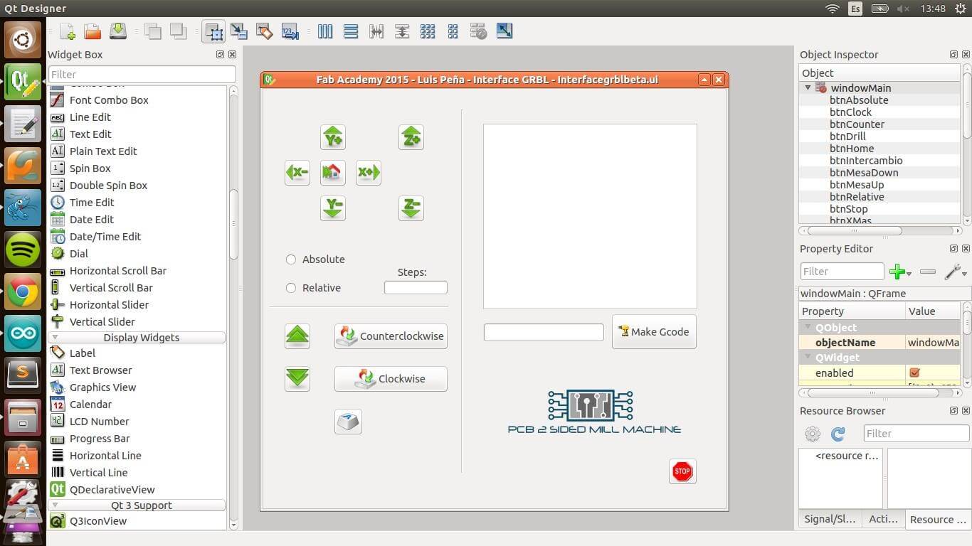
Now we start from the communication to performing a Graphical User Interface (GUI) for control of the axes and the order of sending an Gcode file, for the realization of This interface used the QT Designer Software 4 which is a useful tool for interaction of some IDE's that contains GUI integrated these options, here we made the buttons axis interface and automated changing bit and at the side Right visualization commands shown orders of engines and loaded the file extension Gcode (software Cad.py MIT is used which generates a .png file to a file.gcode). The Qt 4 Designer exports the project with a .ui extension then we open the console where we enter the drive linux .ui extension of a .py extension (command linux "pyiuc4inFile.ui> OutFile.py "to install the unit #sudo
apt-get install pyuic4 dev.tools) to review changes we will use to run the interface in an Editor
Code (Sublime Text 3) where we opened to add modules and modify the initialization parameters. The modules are QtCore and QtGui (python script "import QtCore and QtGui") as well as The class also Ui_Form = Ui Code !, setup () = Create UI and retranslate () = attribute Set. We add code at the end of the main.
the script:
[If_name _ == '__ main__';
app = QtGuiApplication (sys.argv)
ex = Ui_Form ()
ex.show ()
sys.exit (app.exec_ ())]
Finally I run the interface.