


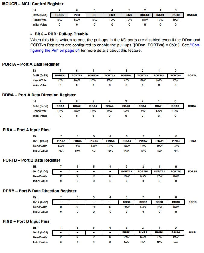
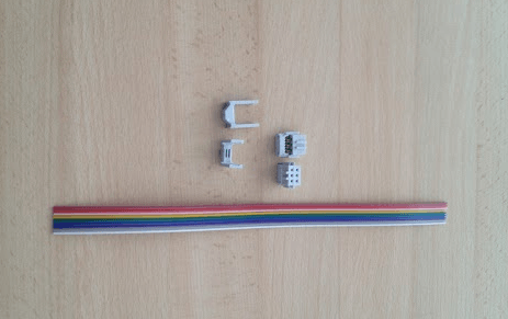
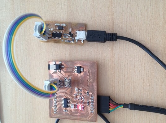
B. Ensambling the ISP connector
First, we cut the secure border from the wire, then select just 6 colors, to the connectors from ISP (MISO, SCK, RST, VCC, MOSI, GND). Pass the wire with the header, and then secure whit the other header, and repeat with the other side. We tested the ISP connector with the Hello Eccho and the FABISP. It worked perfect!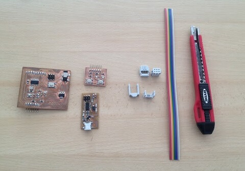
C. Programming with Arduino
Install Arduino IDEDownload and install the Tiny libraries, download from here
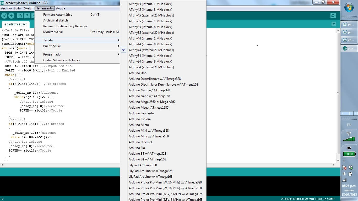
Set board
 >Set Serial Port
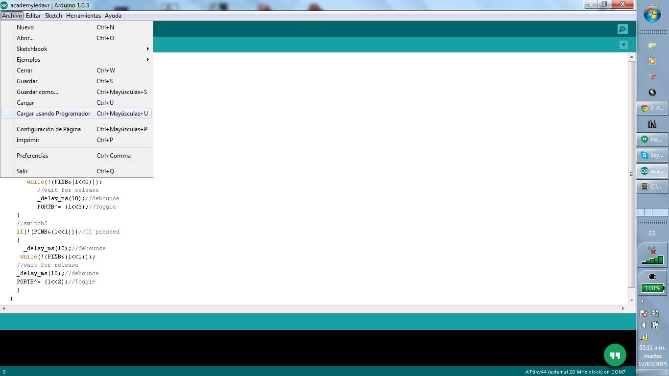
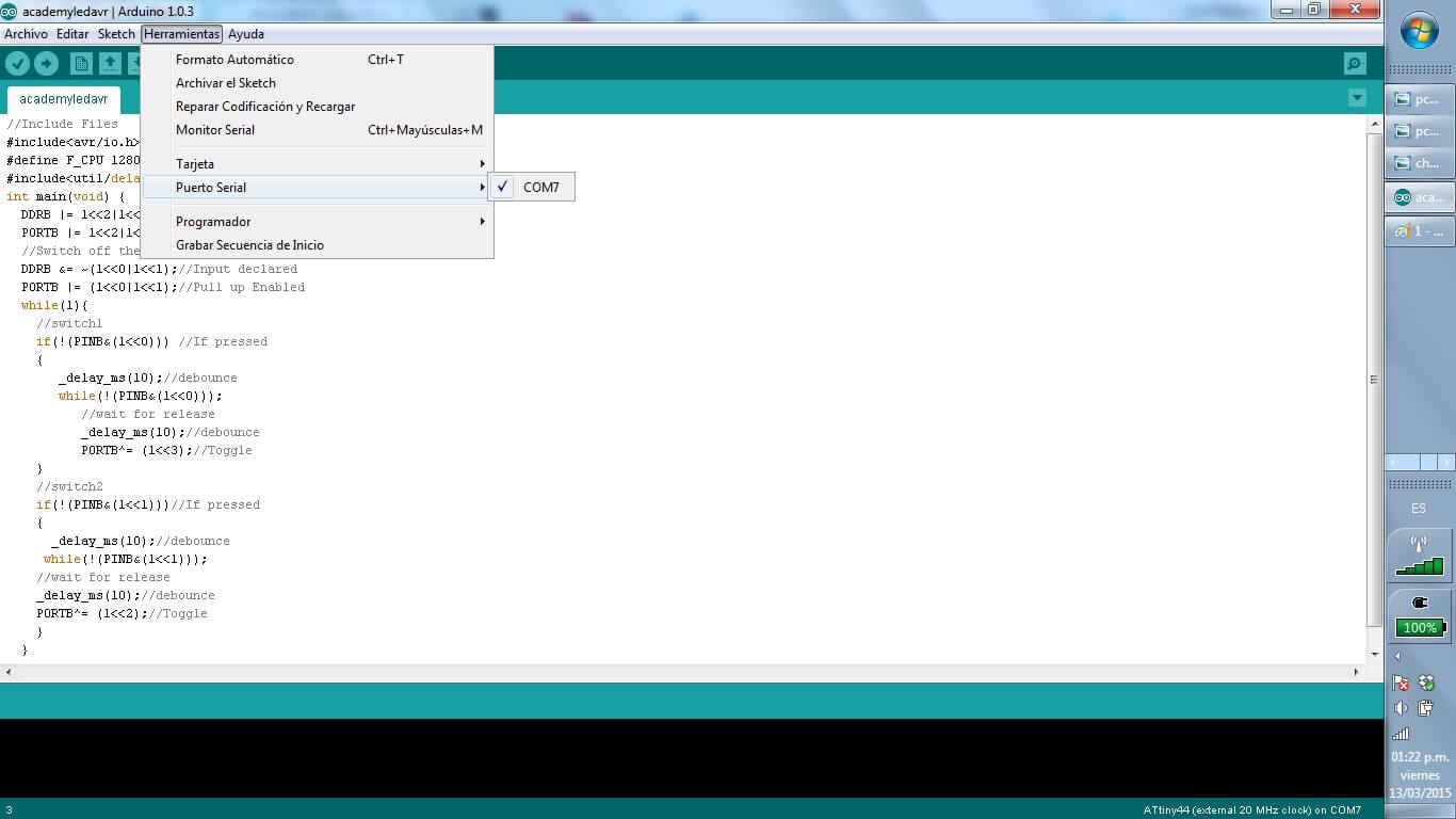 Set Programmer
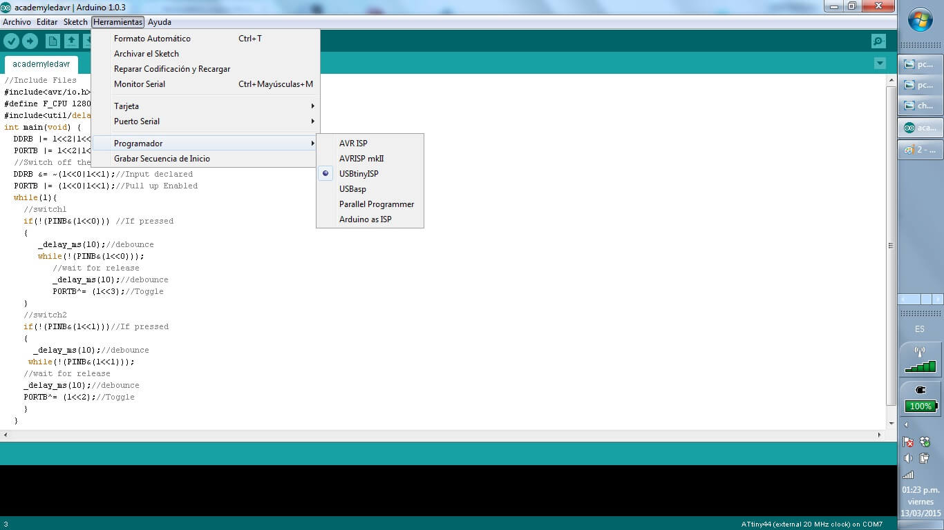 Start Coding!
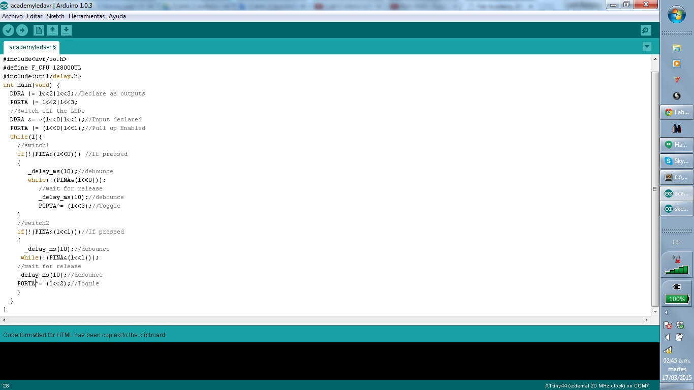
Uploading using Arduino IDE
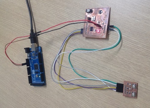
We connect the micro usb to the FABISP, and the FABISP with the ISP connector to the Hello Board, and the Hello Board, with the FTDI wire to the computer.Then we download the file in C, and check its functionality.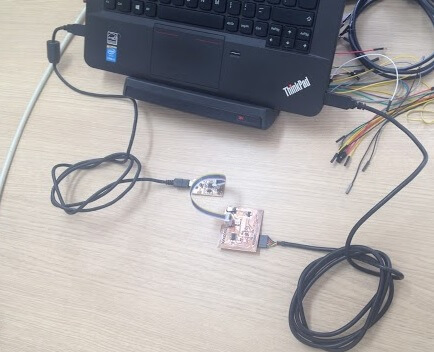
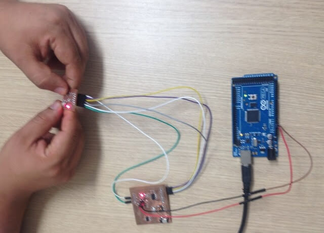
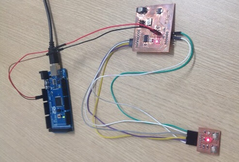
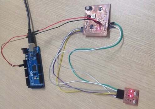 The objective of my program was: to use push two buttons with digital inputs to turn two LEDs on & off .
C code: AVR GCC
The objective of my program was: to use push two buttons with digital inputs to turn two LEDs on & off .
C code: AVR GCC
//Include Files
#include<avr/io.h>
#define F_CPU 128000UL
#include<util/delay.h>
int main(void) {
  DDRA |= 1<<2|1<<3;//Declare as outputs
  PORTA |= 1<<2|1<<3;
  //Switch off the LEDs
  DDRA &= ~(1<<0|1<<1);//Input declared
  PORTA |= (1<<0|1<<1);//Pull up Enabled
  while(1){
    //switch1
    if(!(PINA&(1<<0))) //If pressed
    {
       _delay_ms(10);//debounce
       while(!(PINA&(1<<0)));
          //wait for release
          _delay_ms(10);//debounce
          PORTA^= (1<<3);//Toggle
    }
    //switch2
    if(!(PINA&(1<<1)))//If pressed
    {
      _delay_ms(10);//debounce
     while(!(PINA&(1<<1)));
    //wait for release
    _delay_ms(10);//debounce
    PORTA^= (1<<2);//Toggle
    }
  }
}
Arduino code: Wiring
const int  buttonPin = 0;
const int ledPin = 2;
const int  buttonPin1 = 1;
const int ledPin1 = 3;

int buttonPushCounter = 0;
int buttonState = 0;
int lastButtonState = 0;
int buttonPushCounter1 = 0;
int buttonState1 = 0;
int lastButtonState1 = 0;

void setup(){
  pinMode(buttonPin, INPUT);
  pinMode(ledPin, OUTPUT);
  pinMode(buttonPin1, INPUT);
  pinMode(ledPin1, OUTPUT);
}

void loop(){
  buttonState = digitalRead(buttonPin);
  if (buttonState != lastButtonState){
    if (buttonState == HIGH){
      buttonPushCounter++;
    }
    else{
    }
  }
  lastButtonState = buttonState;

  if (buttonPushCounter % 2 == 0){
    digitalWrite(ledPin, LOW);
  } else{
   digitalWrite(ledPin, HIGH);
  }


  buttonState1 = digitalRead(buttonPin1);
  if (buttonState1 != lastButtonState1){
    if (buttonState1 == HIGH){
      buttonPushCounter1++;
    }
    else{
    }
  }
  lastButtonState1 = buttonState1;

  if (buttonPushCounter1 % 2 == 0){
    digitalWrite(ledPin1, LOW);
  } else{
   digitalWrite(ledPin1, HIGH);
  }
}

In my case I am using the pin 10-11 to the leds and the pin 12-13 for the buttons. for the button in the Arduino IDE. Once that we already have the program, we are going to Tools/Boards to select the plate "Attiny 44 external 20 MHz clock" and we select the programmer "USBtinyISP" We connect the FabISP and the FTDI cable with our FabHello. In the event that our computer does not recognize the FabISP, we download the drivers from the following link: FabISP In the event that our computer does not recognize the FTDI cable,we download the drivers from the following link: FTDI For users of Windows 8, just use the option of automatic search for the drivers of the FTDI. We load the code Enjoy it!